EP1120090A1 - Distraktionsorrichtung für Gesichts- und Kieferchirurgie - Google Patents
Distraktionsorrichtung für Gesichts- und Kieferchirurgie Download PDFInfo
- Publication number
- EP1120090A1 EP1120090A1 EP00200154A EP00200154A EP1120090A1 EP 1120090 A1 EP1120090 A1 EP 1120090A1 EP 00200154 A EP00200154 A EP 00200154A EP 00200154 A EP00200154 A EP 00200154A EP 1120090 A1 EP1120090 A1 EP 1120090A1
- Authority
- EP
- European Patent Office
- Prior art keywords
- bracket
- distraction
- chamber
- distraction screw
- fixed bracket
- Prior art date
- Legal status (The legal status is an assumption and is not a legal conclusion. Google has not performed a legal analysis and makes no representation as to the accuracy of the status listed.)
- Ceased
Links
Images

Classifications
-
- A—HUMAN NECESSITIES
- A61—MEDICAL OR VETERINARY SCIENCE; HYGIENE
- A61B—DIAGNOSIS; SURGERY; IDENTIFICATION
- A61B17/00—Surgical instruments, devices or methods, e.g. tourniquets
- A61B17/56—Surgical instruments or methods for treatment of bones or joints; Devices specially adapted therefor
- A61B17/58—Surgical instruments or methods for treatment of bones or joints; Devices specially adapted therefor for osteosynthesis, e.g. bone plates, screws, setting implements or the like
- A61B17/60—Surgical instruments or methods for treatment of bones or joints; Devices specially adapted therefor for osteosynthesis, e.g. bone plates, screws, setting implements or the like for external osteosynthesis, e.g. distractors, contractors
- A61B17/66—Alignment, compression or distraction mechanisms
- A61B17/663—Alignment, compression or distraction mechanisms for jaw bones, e.g. subcutaneous distractors with external access
Definitions
- the uniplanar distractors have two pin clamps, a distraction screw, and four percutaneous pins.
- the pins are of fixed length and about 8cm long of which about 2 cm is fixed into the bone and 6cm extends out of the bone.
- the diameter of the pin is between 10-15mm in diameter.
- the distractor is placed percutaneously (through the skin of the face). The device is large, has a complex screw, and requires fixation through the skin with long pins. Therefore, fixation and removal needs to be performed under general anesthesia.
- Figure 7.4 discloses a device with a distraction screw of about 3cm long and a diameter larger than about 5mm in diameter.
- the uniplanar distractor has two translating brackets, moving in opposite directions and no fixed bracket. All pieces are welded or soldered together.
- the device is large and complex and requires transmucosal fixation.
- Figure 7.5 discloses a distraction screw of about 4cm long and a diameter of about 6mm.
- the right fixed bracket is about 2.5cm long, about 4cm wide and about 8mm thick.
- the left, translating bracket is about 4cm wide.
- the prominent interconnecting bars are positioned on top of the guiding rails. All pieces are welded or soldered together.
- the device is large and complex and requires transmucosal fixation.
- Unidirectional distraction devices with the numbers 51-500-10, 51-500-15 and 51-500-20 by Martin, each comprises 2 guiding rails, a fixed bracket, a translating bracket, 1 distraction screw, 6 osteosynthesis pins and 1 or more cranks.
- the distractor requires an interconnecting bar between the guiding rails. This distractor is large and requires a complex surgical operation for fixation and removal under general anesthesia.
- Distraction devices that have the numbers 51-525-06, 51-525-09, 51-525-12 and 51-525-15 by Martin, each comprises a fixed bracket with up to 14 perforation, a translating bracket with a cylinder and up to 10 perforations, and 1 chamber.
- the chamber is partially hollow and contains the entire length of a distraction screw, except for the head. Further, the chamber contains the cylinder of the translating bracket.
- the use of many lateral pins could lead to damage to adjacent anatomical structures. The use of a bulky cylinder may be uncomfortable during the period of distraction. Further, it seems that the distraction screw cannot be replaced with an alternative distraction screw without removal of one or more of the brackets.
- a vertical alveolar distractor by Stryker Leibinger comprises a translating bracket, a fixed bracket, 10 to 20 perforations in total, and one distraction screw at a distraction and was presented at a conference in Paris, in June 1999.
- One perforation in the translating bracket is used as a cylinder for the distraction screw.
- the brackets are relatively thick. Some of the perforations are positioned in the distraction gap and interferes with the neo-osteogenic site. The use of many lateral pins could lead to damage to adjacent anatomical structures.
- the invention relates to a device comprising two or more brackets, and a distraction screw.
- the device comprises lateral pins.
- the device comprises one or more guiding rails.
- the device comprises an interconnecting bar connected with another device.
- the invention preferably relates to a device comprising a translating bracket, a fixed bracket, and a distraction screw characterized in that the translating bracket comprises a cylinder, the fixed bracket comprises a chamber, the distraction screw is perpendicular to the brackets.
- the invention relates to a device wherein the distraction screw runs through the cylinder and rests on the chamber of the fixed bracket.
- the invention relates to a device wherein the chamber of the fixed bracket is located entirely below the cylinder of the translating bracket.
- the invention relates to a device wherein the cylinder of the translating bracket is located outside the chamber of the fixed bracket.
- the invention relates to a device wherein the device comprises a guiding rail and/or an interconnecting bar.
- a preferred embodiment of the invention is a distractor composed of four parts, including two brackets, the vertical screw, four titanium lateral (osteosynthetic) pins.
- the present invention further relates to a device comprising a translating bracket, a fixed bracket, and a distraction screw for use in vertical osteogenesis.
- the present invention further relates to a method of manufacturing a device comprising a translating bracket with a cylinder, a fixed bracket, and a distraction screw, wherein distraction screw is tumed through the cylinder.
- the present invention further relates to a method of distracting two bone pieces using a device comprising a translating bracket with a cylinder, a fixed bracket with a chamber, and a distraction screw characterized in that the fixed bracket is connected to one piece of bone, the translating bracket is connected to the other piece of bone, the distraction screw is inserted through the cylinder of the translating bracket and placed on the chamber of the fixed bracket and wherein the two pieces of bone are distracted by turning the distraction screw.
- the present invention further relates to a fixed bracket comprising a chamber and perforations and to the manufacture thereof.
- the present invention further relates to a translating bracket comprising a cylinder and perforations and to the manufacture thereof.
- the dimensions of the device are suitable and tailored to distraction osteogenesis in the resorbed and atrophied orofacial osseous skeleton.
- an attempt is made to provide for all parameters affecting distraction osteogenesis, for instance in patients with the edentulous mandible and/or maxilla jaws, and dentulous (tooth bearing) patients with alveolar defects.
- the simplicity and the size of the device make it easily applicable and more suited in the oral cavity and in the orofacial skeleton.
- the device of the present invention has further advantages over the prior art.
- the device is small without any internal empty space. Its small size allows for implantation underneath the mucosa. The small size further leaves little scar tissue after distraction.
- the design of the device allows for placement and removal through a simple surgical procedure, without the requirement for general anesthesia of the patient.
- the design avoids interference with the site of osteogenesis.
- the device is further designed such that it produces little or no inconvenience or irritation for the patient during the period of distraction.
- a preferred embodiment of the device of the invention allows for changing the distraction screw without removal of the brackets.
- the design of the device makes the chance of infections and other complications particularly small. As a consequence of the design, the device has high rigidity, potentially leading to fewer complications than the devices of the prior art.
- the design avoids micro movements at the site of osteogenesis.
- the device of the invention is preferably used as a maxillofacial distractor, an osteogenic device, or a bone conducing device for the alveolar bone. Before use, the device is preferably sterilized (or autoclaved).
- the device of the invention preferably comprises at least two brackets, for instance up to 3. More preferably, the device contains two brackets.
- one of the brackets is a translating, cranial (upper) bracket and the other a fixed, caudal (lower) bracket.
- 'translating' is defined as being able to move up and down relative to the distraction screw.
- 'fixed bracket' is defined as a bracket that is not moving up and down relative to the distraction screw during distraction, but preferably can be turned relative to the distraction screw.
- the brackets, the distraction screw, the lateral pins and the guiding rails (if present) and the interconnecting bars (if present) are made of biocompatible materials, such as metals, polymers, and mixtures thereof.
- Preferred examples are metals (steel, Titanium), metal alloys (Cobalt-Chromium alloys, Cobalt-Chromium-Nickel, CrCoMo), and polylactides.
- the most preferred example is Titanium. Titanium has extraordinary tissue compatibility.
- each of the brackets is preferably made of one piece of material. Preferably, the material and edges of the entire device are smooth without sharp edges.
- the device preferably has a length of smaller than 35mm, more preferably smaller than 30mm, most preferably smaller than 25mm, for instance 20mm, and preferably larger than 3mm, more preferably larger than 5mm, most preferably larger than 8mm, for instance 10mm.
- the device preferably has a width smaller than 35mm, more preferably smaller than 30mm, most preferably smaller than 25mm, and preferably larger than 1mm, more preferably larger than 2mm, most preferably larger than 3mm.
- the device preferably has a thickness smaller than 35mm, more preferably smaller than 30mm, and preferably larger than 1mm, more preferably larger than 2mm, most preferably larger than 3mm, for instance between 5 and 10mm.
- the translating bracket preferably comprises a cylinder.
- the cylinder is hollow.
- the cylinder is internally threaded.
- the cylinder is located centrally (viewed in the frontal plane) of and anteriorly (viewed in the sagittal plane) to the translating bracket.
- the length of the cylinder runs perpendicularly to the plane of the bracket and perpendicularly to the plane of the distraction screw.
- the inner diameter of the cylinder is preferably from 0.5mm, more preferably from 1 mm, most preferably from 1.5mm and preferably up to 7mm, more preferably up to 6mm, most preferably up to 5mm, in particularly preferably smaller than 4mm, for example 2mm.
- the height of the cylinder is preferably from 0.2mm, more preferably from 0.4mm, most preferably from 0.6mm, particularly larger than 0.8mm and preferably up to 10mm, more preferably up to 8mm, most preferably up to 6mm, for example 2.5mm.
- the width of the cylinder is preferably from 1mm, more preferably from 2mm, most preferably from 3mm, preferably up to 25mm, more preferably up to 20mm, most preferably up to 15mm, for example between 5 and 10.
- the thickness of the cylinder is preferably smaller than 25mm, more preferably smaller than 20mm, most preferably smaller than 15mm and preferably from 1mm, more preferably from 2mm, most preferably from 3mm, for instance between 5 and 10mm.
- the translating bracket may not comprise a perforation. However, it is preferred that the translating bracket comprises one or more perforations.
- the perforations can be used for fixating the translating bracket with lateral pins to the underlying alveolar (jaw) bone that is to be distracted (moved away from the underlying bone).
- the perforations are positioned in the horizontal plane of the translating bracket, and are preferably completely embedded in the bracket.
- the lateral perforations are located perpendicular to the cylinder and perpendicular to the distraction screw.
- the perforations are round.
- the perforations are preferably smooth and not internally threading.
- the perforations match the diameter of the lateral pins and preferably have a diameter of from 0.2mm, more preferably from 0.4mm, most preferably from 0.6mm, preferably up to 5mm, more preferably up to 4mm, for instance 0.9mm.
- the number of perforations of the translating bracket to be used depends on the forces that are exercised on the device during distraction, while, at the same time, damage to the nearby anatomical structures has to be avoided.
- the translating bracket contains at least one perforation, for instance up to 10, preferably up to 8, more preferably up to 6, most preferably up to 4, in particular up to 3, for example two or one perforation.
- the perforations may be located on either side of the cylinder (if present), on one side of the cylinder, or posterior to the cylinder.
- the thickness of the bracket around the perforation is at least 0.1mm, more preferably at least 0.2mm.
- the perforations are placed in a line at an angle relative to the distraction screw.
- This embodiment can be used in regions where more retention for the brackets is required.
- the perforations should be multiple on either side and preferably under an angle relative to the distraction screw in order to counteract the lingual tension forces of the musculature on the inside of the mouth.
- the angle is between 90 and 0 degrees, more preferably between 30 and 60 degrees, for instance at 45 degrees.
- the length is preferably from 0.5mm, more preferably from 1mm, most preferably from 2mm and preferably to 30mm, more preferably to 20mm, most preferably to 15mm, in particular up to 10mm, for instance 3mm.
- the translating bracket preferably has a width of from 2mm, more preferably from 3mm, most preferably from 4mm, and preferably to 25 mm, more preferably to 20 mm, most preferably to 18 mm, in particular to 15mm, for instance from 5mm to 10mm.
- the thickness is preferably larger than 1mm, more preferably larger than 2mm, most preferably larger than 2mm, and in particular larger than 3mm, and preferably up to 25 mm, more preferably up to 20 mm, most preferably up to 15 mm, for instance from 5mm to 10mm.
- the fixed bracket comprises one or more (2, 3 or 4) chambers. More preferably, the device comprises one chamber. One ore more of the chambers may be solid. Preferably, one chamber comprises an aperture.
- the aperture can be in the shape of a cavity. Preferably, the aperture is a hollow tube. More preferably the aperture is a cylinder. Preferably, the chamber is in the shape of a cylinder. This facilitates easy surgical fixation and removal of the device.
- the aperture in the chamber may have different widths at different distances from the chamber surface.
- the aperture in the chamber may be wider (indentation) or tighter (extension) inside the chamber as compared to the opening in the surface of the chamber.
- the diameter of cylindrical aperture in the chamber is from 0.5mm, more preferably from 1mm, most preferably from 1.5mm, preferably up to 7mm, more preferably up to 6mm, most preferably up to 5mm, in particularly preferably smaller than 4mm, for instance 2mm.
- the chamber has an aperture at the top, while the bottom of the aperture is solid and not perforated.
- the bottom of the aperture could be flat, but is preferably V-shaped.
- the inner surface of the chamber is smooth and not threaded.
- the aperture is preferably cylindrically shaped.
- the length of the cylindrically shaped aperture is larger than 0.2mm, more preferably larger than 0.5mm, most preferably larger than 0.8mm and preferably smaller than 25mm, more preferably smaller than 20mm, most preferably smaller than 15mm, for instance 2 or 3mm.
- the length of the chamber is preferably larger than 0.2mm, more preferably larger than 0.4mm, most preferably larger than 0.6mm, particularly larger than 0.8mm and preferably up to 20mm, more preferably to 10mm, most preferably to 8mm, for instance 2.5mm.
- the width of the chamber is preferably from 1 mm, more preferably from 2mm, most preferably from 3mm, preferably up to 25mm, more preferably up to 20mm, most preferably up to 15mm, for example between 5 and 10.
- the chamber preferably has a thickness smaller than 25mm, more preferably smaller than 20mm, most preferably smaller than 15mm and preferably from 1mm, more preferably from 2mm, most preferably from 3mm, for instance between 5 and 10mm.
- the fixed bracket may not comprise a perforation. However, it is preferred that the fixed bracket comprises one or more perforations.
- the perforations can be used for fixating the fixed bracket to the underlying alveolar (jaw) bone with lateral pins.
- the perforations are positioned in the horizontal plane of the fixed bracket, and are preferably completely embedded in the brackets.
- the perforations are round.
- the perforations are preferably smooth and not internally threading.
- the perforations match the diameter of the lateral pins and preferably have a diameter of from 0.2mm, more preferably from 0.4mm, most preferably from 0.6mm, preferably up to 5mm, more preferably up to 4mm, for instance 0.9mm.
- the fixed bracket contains at least one perforation, for instance up to 10, preferably up to 8, more preferably up to 6, most preferably up to 4, in particular up to 3, for example two or one perforation.
- the perforations may be located on either side of the chamber (if present), on one side of the chamber, or posterior to the chamber.
- the thickness of the bracket around the perforation is at least 0.1mm, more preferably at least 0.2mm.
- the perforations are placed in a line at an angle relative to the distraction screw.
- This embodiment can be used in regions where more retention for the brackets is required.
- the perforations should be multiple on either side and preferably under an angle relative to the distraction screw in order to counteract the lingual tension forces of the musculature on the inside of the mouth.
- the angle is between 90 and 0 degrees, more preferably between 30 and 60 degrees, for instance at 45 degrees.
- the length of the fixed bracket is preferably from 0.5mm, more preferably from 1mm, most preferably from 2mm and preferably to 30mm, more preferably to 20mm, most preferably to 15mm, in particular up to 10mm, for instance 3mm.
- the fixed bracket preferably has a width of from 2mm, more preferably from 3mm, most preferably from 4mm, in particular from 25mm, and preferably to 20 mm, more preferably to 18mm, particularly preferred to 15mm, for instance 10 mm.
- the thickness (including the chamber) is preferably larger than 1mm, more preferably larger than 2mm, most preferably larger than 3mm, and preferably up to 25 mm, more preferably up to 20 mm, most preferably up to 15 mm, for instance from 5mm up to 10mm.
- the device of the present invention comprises one or more distraction screws. More preferably, the device comprises one distraction screw.
- the distraction screw comprises a head, a shaft and a tip.
- the length of the distraction screw may vary depending on the required distraction.
- the length of the screw is up to 35mm, more preferably up to 30mm, most preferably up to 25mm, for instance 20mm, and preferably larger than 3mm, more preferably larger than 5mm, most preferably larger than 8mm, for instance 10mm.
- the head of the distraction screw has a groove.
- the groove covers the entire diameter of the head.
- the circumference of the head is preferably hexagonally shaped.
- the head of the distraction screw is preferably marked on the surface between the center and the side of the screw. The mark may be an indentation in the screw and/or may consist of a different color.
- the shaft of the distraction screw is threaded.
- the pitch of the thread is larger than 0.1mm, more preferably larger than 0.15mm, most preferably larger than 0.2mm, and preferably smaller than 4mm, more preferably smaller than 3mm, most preferably smaller than 2.5 mm.
- Examples of a pitch are 0.25mm, 0.3mm, 0.5mm, 1mm, 1.5mm and 2mm.
- the diameter of the shaft is smaller than 7mm, more preferably smaller than 6mm, most preferably smaller than 5mm, in particularly preferably smaller than 4mm, preferably larger than 0.5mm more preferably larger than 1mm, most preferably larger than 1.5mm, for instance 2mm.
- the distraction screw is straight.
- the shaft may have one or more extensions and/or indentations.
- the extensions or indentations may be circular and/or lateral.
- the diameter of these extensions may be at least 0.5mm larger than the diameter of the shaft, more preferably at least 1mm, most preferably at least 2mm, and preferably at most 20mm, more preferably at most 16mm.
- the diameter of these indentations may be at least 0.1mm smaller than the diameter of the shaft, more preferably at least 0.2mm, and preferably at most 3mm, more preferably at most 2mm.
- the tip of the distraction screw may be flat, spherical or V-shaped. If V-shaped, the distraction screw may be smooth and polished tip.
- the brackets can be glued on the underlying anatomic structures. However, to be able to withstand larger forces, the brackets are preferably connected through lateral pins. Preferably, the pins are threaded.
- the pins may vary in length depending on the thickness of the underlying alveolar (jaw) bone, but are preferably from 2mm, more preferably 3mm, most preferably 4mm, preferably up to 20mm, more preferably 10mm, most preferably up to 8mm, particularly up to 6mm in length.
- the diameter of the pins is preferably from 0.2mm, more preferably from 0.4mm, most preferably from 0.6mm, preferably up to 5mm, more preferably up to 4mm, for instance 0.9mm.
- the head of the lateral pin has a groove.
- the groove covers the entire diameter of the head.
- the pitch of the threads of the lateral pins is larger than 0.1mm, more preferably larger than 0.15mm, most preferably larger than 0.2mm, and preferably smaller than 4mm, more preferably smaller than 3mm, most preferably smaller than 2.5 mm.
- Examples of a pitch are 0.25mm, 0.3mm, 0.5mm, 1mm, 1.5mm and 2mm.
- one or more of the brackets comprise one or more guiding rails.
- the guiding rail is preferably connected to the fixed bracket.
- the guiding rail is preferably continuous with the bracket, i.e. the bracket and the guiding rail are made from one piece of material.
- the guiding rail has a smooth and polished surface.
- the guiding rail is preferably connected at the posterior (back) part of the bracket, although the guiding rail(s) may also be connected elsewhere.
- the guiding rail is preferably shorter than the distraction screw.
- the guiding rails has a length of smaller than 35mm, more preferably smaller than 30mm, most preferably smaller than 25mm and preferably up from 3mm, more preferably up from 5mm, most preferably up from 8mm, for instance from 15 to 20mm.
- the guiding rail has a width of from 0.1mm, more preferably from 0.5mm and preferably up to 6mm, more preferably up to 5mm, most preferably up to 4mm, for instance 3mm.
- the guiding rail has a thickness of from 0.1mm, more preferably 0.5mm and preferably up to 3mm, more preferably up to 2mm, most preferably up to 1.5mm for instance 1 mm.
- the guiding rail are preferably not connected with a bar. Such a device would increase the size of the distractor and potentially lead to complications.
- two or more distractors may be indicated, for instance to move larger osteotomised (cut) bone.
- the use of bigger distractors would increase the chance of infections. Also, bigger distractors are less likely to be tolerated by the patient.
- an interconnecting bar between two brackets may be used. A gradual distraction over a long trajectory with two or more distractors is preferred over distraction with a single large distractor.
- an embodiment of the present invention relates to two or more (up to 3, preferably 2) devices with one or more (up to 2; preferably 1) of the brackets connected to the brackets of another distractor by way of one or more (preferably 1) interconnecting bars.
- a guiding rail is used for this embodiment of the invention.
- the lateral perforations through each of the brackets may be situated within the interconnecting bar.
- the device comprises brackets, and a distraction screw.
- the distraction screw runs perpendicularly through the cylinder on the translating bracket.
- the screw can turn in thread of the cylinder of the translating bracket.
- the distraction screw rests on (preferably a smooth area of) the fixed bracket after placement by the surgeon. By turning the distraction screw, the screw will push against the fixed bracket and move the translating bracket along the thread of the distraction screw.
- the chamber of the fixed bracket is preferably located entirely on one side (for instance below) of the cylinder of the translating bracket.
- the cylinder of the translating bracket is located entirely outside (and preferably on one side) of the chamber of the fixed bracket.
- the chamber of the fixed bracket and the rest of the fixed bracket are preferably located on the same side of the translating bracket.
- the chamber of the fixed bracket does not extend to the other side of the cylinder of the translating bracket.
- the distraction screw rests on the surface of the fixed bracket.
- the distraction screw rests against the surface of the fixed bracket on the side facing the translating bracket.
- this surface is part of the chamber of the fixed bracket.
- the surface can, for instance, be the outer surface of the chamber on fixed bracket and/or the bottom of the aperture in the chamber.
- the shaft of the distraction screw may optionally have one or more extensions (for instance circular and lateral) and/or one or more indentations (for instance circular and lateral). These may be positioned at one or more locations towards and/or at the tip of the distraction screw.
- the distraction screw is preferably positioned in the aperture of the fixed bracket. Lateral extensions of the distraction screw may rest against the surface of the fixed bracket. Extensions and/or indentations of the distraction screw may also be positioned inside the fixed bracket and match with indentations and/or extensions of the aperture of the fixed bracket. Such extensions and indentations may prevent the distraction screw from moving out or through (up and down) the fixed bracket. Use of these extensions or indentations may stabilize the distraction screw relative to the fixed bracket and make the connection between the fixed bracket and the distraction screw more tightly.
- the chamber of the fixed bracket has an aperture on the surface at the side facing the translating bracket.
- the aperture extends into the chamber.
- the bottom of the aperture is solid and not perforated on the other side of the chamber.
- the distraction screw is inserted and turned freely in the aperture of the fixed bracket.
- the distraction screw rests on the bottom of the aperture and/or on the outer surface of the fixed bracket (for instance through a lateral extension that might be circular, as discussed above).
- the distraction screw can be inserted in the fixed bracket, for instance for a distance from 0.5mm to 3mm, may stabilize the distraction screw relative to the fixed bracket and make the connection between the fixed bracket and the distraction screw more tightly.
- the distraction screw does not have extensions inside in the aperture of the chamber of the fixed bracket. This allows the distraction screw to be removed from the fixed bracket through the aperture at the top and from the translating bracket. This preferred embodiment allows the surgeon to replace the distraction screw, for instance with a longer distraction screw, during the process of distraction and without unscrewing the brackets from the underlying bone.
- the device of the invention does not interfere with the site of osteogenesis. It is therefore preferred that the brackets do not have extensions that are directed perpendicularly to the distraction screw and/or perpendicularly to the brackets, at a level between the brackets and directed away from the distraction screw into the site of osteogenesis. Preferably, the distraction screw is not present in the site of osteogenesis.
- the lateral pins are located perpendicularly to the distraction screw and preferably perpendicularly to the brackets.
- the lateral pins do preferably not interfere with the osteogenesis and preferably do not damage the surrounding anatomical structures.
- the optional guiding rail slides through the opposite bracket. For instance, if connected to the fixed bracket, it slides through the translating bracket, or visa versa.
- the rail guides the brackets in the right direction and makes the connection more tightly.
- the guiding rail is most preferably connected at the posterior (back) part of the bracket, posterior to the distraction screw and parallel to the distraction screw.
- the guiding rail(s) may also be connected elsewhere, for instance around the distraction screw.
- the guiding rail may also be placed parallel and adjacent, for instance on the sides or in the front of the distraction screw. If placed in the front, the guiding rail will also protect the anatomical structures from being exposed to the distraction screw.
- the Lateral Pins may vary in length and may be used either for monocortical or bicortical fixation.
- the device of the present invention is preferably manufactured by preparing the translating bracket with a cylinder, the fixed bracket and the distraction screw, and turning the distraction screw through the cylinder of the translating bracket.
- the device comprises lateral pins.
- the parts of the device of the present invention are manufactured without using welding or soldered connections. Instead each part is preferably manufactured out of one solid piece through casting. Therefore, preferably the distraction screw is manufactured out of one piece, preferably the translating bracket is manufactured out of one piece, and preferably the fixed bracket is manufactured out of one piece.
- the device of the present invention offers advantages above the distractors of the prior art.
- the brackets of the device of the present invention enables the surgeon to position the distractor accurately without damaging the adjacent anatomical structures.
- Some devices of the prior art require bending or cutting the microplates for adaptation in e.g. alveolar distraction of single diasthemas (gap resulting from the removal of a tooth).
- the construction of the brackets is preferably rigid and manufactured out of one piece and is preferably not soldered, as is the case in many devices of the prior art.
- the brackets are positioned on the buccal (outside) surface of the alveolar (jaw) bone and do not interfere with the neo-osteogenic (newly grown bone) site.
- elements for instance the microplates
- the microplates are bent to and lie within the neo-osteogenic (newly grown bone) gap and interfere with the augmented bone. Therefore removal of the microplates after completion of distraction osteogenesis does not contribute to the stability of the newly distracted layer of bone and will lead to unpredictable results.
- the device as proposed may be applied in the entire orofacial skeleton in order to lengthen and augment the jaws vertically and/or horizontally.
- the device of the present invention is preferably used for vertical osteogenesis.
- the device of the present invention is used for distraction of a piece of bone from the jaw.
- the device of the invention can be used for distraction of a single tooth defect.
- the device can also be used for distraction of a resorbed alveolar ridge.
- the osteotomies can be made and the microdistractors can be fixated to the mandible.
- the device is preferably sterilized in an autoclave before use. Therefore the device is preferably autoclaved.
- a further embodiment of the invention relates to a method of distracting two pieces of bone using the device of the present invention.
- the fixed bracket is connected to one piece of bone and the translating bracket is connected to the other piece of bone that is to be distracted from the other piece of bone.
- the distraction screw is inserted through the cylinder of the translating bracket and placed on the chamber of the fixed bracket. By turning the distraction screw, the two pieces of bone are distracted.
- the piece of bone that is to be distracted is cut from the underlying jaw and the translating bracket is attached thereto.
- the fixed bracket is attached to the underlying bone, for instance the jaw.
- the device After placement of the device of the invention in the jaw of a patient, the device is preferably left for a period of 3 to 7 days. After this period, the translating bracket can be moved up by 0.5 to 1.0mm per day.
- the distraction ranges from a 2mm to an extreme of 5cm, more preferably from 5mm to 30mm, most preferably up to 20mm.
- the entire distractor lies underneath the mucoperiost and will be activated one week after insertion, i.e. when healing of the tissues have commenced. It is enwrapped in a soft tissue envelope (mucoperiost). This is a submucosal fixation. Hardly any friction is possible which prevent fraction of the device and the underlying pieces of bone.
- the distracted bone may for instance be used for placement of a dental implant.
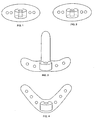
- Figure 1 presents a translating bracket with perforations and with a cylinder with an internal thread.
- Figure 2 presents a fixed bracket with perforations and with a chamber that comprises an internal cylindrical aperture.
- Figure 3 presents a fixed bracket with perforations, with a chamber and with a guiding rail.
- Figure 4 presents a fixed bracket with a chamber and with the line of the perforations under an angle of about 45 degrees.
- Figure 5 presents an example of the chamber where the chamber is pierced through with a cylindrically shaped aperture.
- Figure 6 is a chamber with a cylindrically shaped aperture that only partially pierces the chamber.
- Figure 7 presents a chamber where the aperture becomes broader but does not entirely pierce the chamber.
- Figure 8 presents a chamber with an aperture that becomes wider towards the middle of the chamber.
- Figure 9 presents a chamber where the cylindrically shaped aperture only partially pierces the chamber and the bottom of the aperture is V-shaped.
- Figure 10 presents a distraction screw.
- Figure 11 presents a distraction screw with an extension and with an indentation.
- Figure 12 presents a lateral pin.
- the translating bracket comprises a cylinder, two perforations and two pins that match the perforations.
- the cylinder has an internal thread.
- the cylinder is located centrally (viewed in the frontal plane) of and anteriorly (viewed in the sagittal plane) to the translating bracket.
- the length of the cylinder runs perpendicularly to the plane of the bracket and perpendicularly to the plane of the distraction screw.
- the inner diameter of the cylinder is 2.0mm, the thickness of the cylinder wall is 1.5mm and the height of the cylinder is 3.0mm.
- the translating bracket comprises 2 perforations.
- the perforations are positioned in the horizontal plane of the translating bracket, and are completely embedded in the bracket.
- the perforations are round, smooth and not internally threading.
- the perforations match the diameter of the lateral pins and have a diameter of 0.9mm.
- the perforations are located on either side of the cylinder.
- the thickness of the bracket around the perforation is 3.0mm.
- the line of the perforations in the translating bracket is 90 degrees relative to the distraction screw, but might be placed at an angle of 45 degrees at an angle if more retention is required.
- the translating bracket has a width of smaller than 10mm, a length of about 5mm, and a thickness (including the cylinder) of about 5mm.
- the fixed bracket comprises one chamber with an aperture in the shape of a hollow cylinder.
- the diameter of the aperture in the chamber is 1.9mm.
- the chamber has an aperture at the top, while the bottom of the aperture is solid and not perforated.
- the bottom of the aperture is flat.
- the inner surface of the chamber is smooth and not threaded.
- the length of the cylindrically shaped aperture is 1.2mm.
- the length of the chamber is about 2.5mm.
- the width of the chamber is about 4mm.
- the chamber has a thickness of about 5mm.
- the fixed bracket comprises 2 perforations on either side of the chamber.
- the perforations are positioned in the horizontal plane of the fixed bracket and are completely embedded in the brackets.
- the perforations are round, smooth and not internally threading.
- the perforations match the diameter of the lateral pins and have a diameter of about 0.9mm.
- the fixed bracket has the same dimensions as the translating bracket.
- the device comprises one distraction screw with a head, a shaft and a tip.
- the length of the distraction screw is 20mm.
- the head of the distraction screw has a groove.
- the groove covers the entire diameter of the head.
- the circumference of the head is hexagonally shaped.
- the head of the distraction screw is marked on the surface between the center and the side of the screw. The mark may be a colored indentation in the screw.
- the shaft of the distraction screw is threaded.
- the pitch of the thread is 0.25mm.
- the diameter of the shaft is 1.9mm.
- the distraction screw is straight and does not have any extensions or indentations.
- the tip of the distraction screw is flat, smooth and polished tip.
- the lateral pins are threaded and are 4mm in length with a diameter of 0.9mm.
- the head of the lateral pin has a groove covering the entire diameter of the head.
- the pitch of the threads of the lateral pins is about 0.9mm.
- the device comprises a guiding rail continuously with the fixed bracket and made from one piece of Titanium with a smooth and polish surface. It was connected at the posterior (back) part of the fixed bracket and has a rounded top.
- the guiding rail has a length of just lower than the distraction screw.
- the guiding rail has a width of from 3mm.
- the guiding rail has a thickness of from 1mm.
- the device does not have an interconnecting bar.
- the distraction screw runs perpendicularly through the cylinder on the translating bracket.
- the screw turns in thread of the cylinder of the translating bracket.
- the distraction screw rests on the fixed bracket. By turning the distraction screw, the screw will push against the fixed bracket and move the translating bracket along the thread of the distraction screw.
- the chamber of the fixed bracket is located entirely on one side of the cylinder of the translating bracket.
- the cylinder of the translating bracket is located entirely outside of the chamber of the fixed bracket.
- the chamber of the fixed bracket and the rest of the fixed bracket are located on the same side of the translating bracket. Thus, the chamber of the fixed bracket does not extend to the other side of the cylinder of the translating bracket.
- the distraction screw rests on the bottom of the aperture in the chamber.
- the distraction screw is inserted and turned freely in the aperture of the fixed bracket.
- the distraction screw rests on the bottom of the aperture.
- the distraction screw is inserted in the fixed bracket for about 1.5mm.
- the distraction screw does not have extensions inside in the aperture of the chamber of the fixed bracket. This allows the distraction screw to be removed from the fixed bracket through the aperture at the top and from the translating bracket. This allows the surgeon to replace the distraction screw, for instance with a longer distraction screw, during the process of distraction and without unscrewing the brackets from the underlying bone.
- the device of the invention does not interfere with the site of osteogenesis.
- the brackets do not have extensions that are directed perpendicularly to the distraction screw and perpendicularly to the brackets, at a level between the brackets and directed away from the distraction screw into the site of osteogenesis. Also, the distraction screw is not present in the site of osteogenesis.
- the lateral pins are located perpendicularly to the distraction screw and perpendicularly to the brackets.
- the lateral pins have a length of about 4mm.
- the lateral pins do not interfere with the osteogenesis and do not damage the surrounding anatomical structures.
- the guiding rail slides through the translating bracket.
- the guiding rail is connected at the posterior (back) part of the bracket, posterior to the distraction screw and parallel to the distraction screw.
- the device is made by casting the translating bracket with a cylinder, the fixed bracket and the distraction screw, and tuming the distraction screw through the cylinder of the translating bracket.
- the parts of the device are manufactured without using welding or soldered connections. Instead each part is manufactured out of one solid piece through casting.
- the translated bracket is connected to the osteotomized mandible piece to be distracted and that was cut from the underlying model.
- the fixed bracket was attached to the underlying mandible, the piece not to be distracted.
- the distraction screw is inserted through the cylinder of the translating bracket and placed on the chamber of the fixed bracket. By tuming the distraction screw, the piece is distracted for 20mm. The same was done for the maxilla, instead of the mandible.
- the vertical upward movement of the translating bracket follows without difficulty and the fixated cranial (upper) part of the mandible can be lifted in a controlled fashion.
- the rigidity of the device is satisfying considering the absence of soft tissues on the model. It is not possible to bend or distort the device by digital tension force.
- a second device is manufactured. This device is the same as the first device, but without the guiding rail. Again the device distracted a piece of the model for 20mm.
- a third device was manufactured. This device is half the size of the second device, apart from the length of the distraction screw, which was also 20mm. Again the device distracted a piece of the model for 20mm.
- a device with guiding rail When distracted at a length of 20mm, a device with guiding rail is more stable and shows less torque.
- a device without guiding rail shows neither distortion nor bending at digital pressure in a mandibular model. While absent in the mandibular model, in the patient's mouth the periosteum and musculo-mucosal envelope would give additional rigidity and buccal tension to the device, likely to prevent the aforementioned slight transverse movement at maximum distraction length of 20mm.
- the device was successfully tested in vitro.
- the design of the device takes into consideration the anatomical dimensions of the resorbed and atrophied mandible.
Priority Applications (7)
| Application Number | Priority Date | Filing Date | Title |
|---|---|---|---|
| EP00200154A EP1120090A1 (de) | 2000-01-17 | 2000-01-17 | Distraktionsorrichtung für Gesichts- und Kieferchirurgie |
| US10/181,848 US7252668B2 (en) | 2000-01-17 | 2001-01-17 | Distraction device for maxillofacial surgery |
| AT01903659T ATE282367T1 (de) | 2000-01-17 | 2001-01-17 | Distraktionsvorrichtung für gesichts- und kieferchirurgie |
| EP01903659A EP1251789B1 (de) | 2000-01-17 | 2001-01-17 | Distraktionsvorrichtung für gesichts- und kieferchirurgie |
| AU2001231684A AU2001231684A1 (en) | 2000-01-17 | 2001-01-17 | Distraction device for maxillofacial surgery |
| DE60107201T DE60107201D1 (de) | 2000-01-17 | 2001-01-17 | Distraktionsvorrichtung für gesichts- und kieferchirurgie |
| PCT/EP2001/000567 WO2001052755A1 (en) | 2000-01-17 | 2001-01-17 | Distraction device for maxillofacial surgery |
Applications Claiming Priority (1)
| Application Number | Priority Date | Filing Date | Title |
|---|---|---|---|
| EP00200154A EP1120090A1 (de) | 2000-01-17 | 2000-01-17 | Distraktionsorrichtung für Gesichts- und Kieferchirurgie |
Publications (1)
| Publication Number | Publication Date |
|---|---|
| EP1120090A1 true EP1120090A1 (de) | 2001-08-01 |
Family
ID=8170914
Family Applications (2)
| Application Number | Title | Priority Date | Filing Date |
|---|---|---|---|
| EP00200154A Ceased EP1120090A1 (de) | 2000-01-17 | 2000-01-17 | Distraktionsorrichtung für Gesichts- und Kieferchirurgie |
| EP01903659A Expired - Lifetime EP1251789B1 (de) | 2000-01-17 | 2001-01-17 | Distraktionsvorrichtung für gesichts- und kieferchirurgie |
Family Applications After (1)
| Application Number | Title | Priority Date | Filing Date |
|---|---|---|---|
| EP01903659A Expired - Lifetime EP1251789B1 (de) | 2000-01-17 | 2001-01-17 | Distraktionsvorrichtung für gesichts- und kieferchirurgie |
Country Status (6)
| Country | Link |
|---|---|
| US (1) | US7252668B2 (de) |
| EP (2) | EP1120090A1 (de) |
| AT (1) | ATE282367T1 (de) |
| AU (1) | AU2001231684A1 (de) |
| DE (1) | DE60107201D1 (de) |
| WO (1) | WO2001052755A1 (de) |
Cited By (2)
| Publication number | Priority date | Publication date | Assignee | Title |
|---|---|---|---|---|
| US7361177B2 (en) * | 2002-05-29 | 2008-04-22 | Stryker Leibinger Gmbh & Co. Kg | System and method for providing fastening elements for a bone plate |
| CN111655190A (zh) * | 2017-11-24 | 2020-09-11 | 颅面科技股份有限公司 | 改进的上颌扩弓器和牵引器装置 |
Families Citing this family (26)
| Publication number | Priority date | Publication date | Assignee | Title |
|---|---|---|---|---|
| DE10212815A1 (de) * | 2002-03-22 | 2003-10-02 | Ernst Fuchs | Distraktionsgerät für die Osteogenese |
| US6755839B2 (en) * | 2002-06-19 | 2004-06-29 | Sdgi Holdings, Inc. | Adjustable surgical guide and method of treating vertebral members |
| US20050049595A1 (en) * | 2003-09-03 | 2005-03-03 | Suh Sean S. | Track-plate carriage system |
| US7909860B2 (en) | 2003-09-03 | 2011-03-22 | Synthes Usa, Llc | Bone plate with captive clips |
| US7686836B2 (en) * | 2004-05-13 | 2010-03-30 | Kls-Martin, L.P. | Bone distractor and method |
| US7875033B2 (en) * | 2004-07-19 | 2011-01-25 | Synthes Usa, Llc | Bone distraction apparatus |
| WO2006108160A1 (en) * | 2005-04-06 | 2006-10-12 | Stevens Institute Of Technology | Intra-oral distraction device |
| US20060276787A1 (en) * | 2005-05-26 | 2006-12-07 | Accin Corporation | Pedicle screw, cervical screw and rod |
| US7909610B1 (en) | 2006-12-21 | 2011-03-22 | Amato Craniofacial Engineering, LLC | Computer-aided system of orthopedic surgery |
| US20080228191A1 (en) * | 2007-03-13 | 2008-09-18 | Howmedica Osteonics Corp. | Femoral elevator |
| US20080255567A1 (en) * | 2007-04-10 | 2008-10-16 | Joseph Accordino | Spinal distraction system |
| US20090192514A1 (en) * | 2007-10-09 | 2009-07-30 | Feinberg Stephen E | Implantable distraction osteogenesis device and methods of using same |
| DE102008034300A1 (de) * | 2008-07-23 | 2010-01-28 | Lucas Automotive Gmbh | Fahrzeugscheibenbremse |
| US20100104999A1 (en) | 2008-10-23 | 2010-04-29 | Bulloch Scott E | Apparatus, System, and Method for Intra-Oral Distraction |
| CN101569560B (zh) * | 2009-05-05 | 2011-04-20 | 中国人民解放军第四军医大学口腔医院 | 个体化上颌牙槽骨弧形牵张器 |
| US8435270B2 (en) | 2010-04-29 | 2013-05-07 | Synthes Usa, Llc | Orthognathic implant and methods of use |
| US9066733B2 (en) | 2010-04-29 | 2015-06-30 | DePuy Synthes Products, Inc. | Orthognathic implant and methods of use |
| US9867638B2 (en) * | 2011-11-25 | 2018-01-16 | University Of Cape Town | Transport distraction apparatus |
| CN103654978B (zh) * | 2012-09-14 | 2016-06-29 | 陈碧芝 | 齿槽骨扩增装置及其所用纵向扩增套件 |
| US9700353B2 (en) | 2012-11-27 | 2017-07-11 | Stryker European Holdings I, Llc | Pediatric internal mandibular distractor |
| EP2742883B1 (de) | 2012-12-12 | 2016-07-27 | Stryker European Holdings I, LLC | Chirurgieabstandseinstellungsbaugruppe für Knochendistraktor |
| WO2015187123A1 (en) * | 2014-06-02 | 2015-12-10 | Albany Medical College | Dynamic decompressive craniotomy fixation devices and related methods |
| US10166053B2 (en) | 2014-12-30 | 2019-01-01 | Stryker European Holdings I, Llc | Distractor with bidirectional rotation control |
| TWI561206B (en) * | 2016-04-01 | 2016-12-11 | E Da Hospital | A regulatable external fixator |
| TWI645832B (zh) * | 2017-09-18 | 2019-01-01 | China Medical University | 下顎手術張撐調整器 |
| CN109330719A (zh) * | 2018-10-31 | 2019-02-15 | 浙江大学 | 一种自锁型骨支持抗回旋骨牵张器 |
Citations (5)
| Publication number | Priority date | Publication date | Assignee | Title |
|---|---|---|---|---|
| JPH1043203A (ja) * | 1996-08-07 | 1998-02-17 | Keisei Ika Kogyo Kk | 骨延長器 |
| US5769850A (en) * | 1996-10-16 | 1998-06-23 | Chin; Martin | Apparatus and method for submergible, self-retaining distraction osteogenesis |
| DE29813087U1 (de) * | 1998-07-22 | 1998-12-24 | Leibinger Medizintech | Distraktionsvorrichtung |
| US5895387A (en) * | 1996-10-09 | 1999-04-20 | Romulo Guerrero | Method of craniofacial bone distraction |
| US5980252A (en) * | 1995-05-08 | 1999-11-09 | Samchukov; Mikhail L. | Device and method for enhancing the shape, mass, and strength of alveolar and intramembranous bone |
Family Cites Families (7)
| Publication number | Priority date | Publication date | Assignee | Title |
|---|---|---|---|---|
| DE19620525A1 (de) * | 1996-05-22 | 1997-11-27 | Gmt Medizinische Technik Gmbh | Ellbogengelenk-Endoprothese |
| US5885290A (en) | 1996-12-09 | 1999-03-23 | Guerrero; Cesar A. | Intra-oral bone distraction device |
| US5899940A (en) * | 1997-02-11 | 1999-05-04 | Carchidi; Joseph Edward | Maxillofacial anchoring system for alveolar and small bone skeletal distraction |
| DE29716635U1 (de) | 1997-09-16 | 1997-10-30 | Leibinger Medizintech | Distraktionsvorrichtung zur Behandlung von Knochendefekten |
| JP2001037767A (ja) * | 1999-08-02 | 2001-02-13 | Kyowa Tokei Kogyo Kk | 骨調整具 |
| US6383189B1 (en) * | 1999-09-13 | 2002-05-07 | Brian Schumacher | Driver tool for bone distractor with shaft extension |
| DE29921046U1 (de) * | 1999-11-30 | 2000-05-11 | Leibinger Medizintech | Knochendistraktor |
-
2000
- 2000-01-17 EP EP00200154A patent/EP1120090A1/de not_active Ceased
-
2001
- 2001-01-17 AU AU2001231684A patent/AU2001231684A1/en not_active Abandoned
- 2001-01-17 US US10/181,848 patent/US7252668B2/en not_active Expired - Fee Related
- 2001-01-17 WO PCT/EP2001/000567 patent/WO2001052755A1/en active IP Right Grant
- 2001-01-17 DE DE60107201T patent/DE60107201D1/de not_active Expired - Lifetime
- 2001-01-17 AT AT01903659T patent/ATE282367T1/de not_active IP Right Cessation
- 2001-01-17 EP EP01903659A patent/EP1251789B1/de not_active Expired - Lifetime
Patent Citations (5)
| Publication number | Priority date | Publication date | Assignee | Title |
|---|---|---|---|---|
| US5980252A (en) * | 1995-05-08 | 1999-11-09 | Samchukov; Mikhail L. | Device and method for enhancing the shape, mass, and strength of alveolar and intramembranous bone |
| JPH1043203A (ja) * | 1996-08-07 | 1998-02-17 | Keisei Ika Kogyo Kk | 骨延長器 |
| US5895387A (en) * | 1996-10-09 | 1999-04-20 | Romulo Guerrero | Method of craniofacial bone distraction |
| US5769850A (en) * | 1996-10-16 | 1998-06-23 | Chin; Martin | Apparatus and method for submergible, self-retaining distraction osteogenesis |
| DE29813087U1 (de) * | 1998-07-22 | 1998-12-24 | Leibinger Medizintech | Distraktionsvorrichtung |
Non-Patent Citations (2)
| Title |
|---|
| DATABASE WPI Section PQ Week 199817, Derwent World Patents Index; Class P31, AN 1998-187134, XP002140738 * |
| PATENT ABSTRACTS OF JAPAN vol. 1998, no. 6 30 April 1998 (1998-04-30) * |
Cited By (3)
| Publication number | Priority date | Publication date | Assignee | Title |
|---|---|---|---|---|
| US7361177B2 (en) * | 2002-05-29 | 2008-04-22 | Stryker Leibinger Gmbh & Co. Kg | System and method for providing fastening elements for a bone plate |
| CN111655190A (zh) * | 2017-11-24 | 2020-09-11 | 颅面科技股份有限公司 | 改进的上颌扩弓器和牵引器装置 |
| CN111655190B (zh) * | 2017-11-24 | 2022-07-05 | 颅面科技股份有限公司 | 改进的上颌扩弓器和牵引器装置 |
Also Published As
| Publication number | Publication date |
|---|---|
| AU2001231684A1 (en) | 2001-07-31 |
| US7252668B2 (en) | 2007-08-07 |
| US20030105463A1 (en) | 2003-06-05 |
| WO2001052755A1 (en) | 2001-07-26 |
| DE60107201D1 (de) | 2004-12-23 |
| ATE282367T1 (de) | 2004-12-15 |
| EP1251789B1 (de) | 2004-11-17 |
| EP1251789A1 (de) | 2002-10-30 |
Similar Documents
| Publication | Publication Date | Title |
|---|---|---|
| EP1120090A1 (de) | Distraktionsorrichtung für Gesichts- und Kieferchirurgie | |
| EP1250100B1 (de) | Gerät zur intraoralen distraktionsosteosynthese zum erweitern des oberkiefers | |
| Obwegeser | Orthognathic surgery and a tale of how three procedures came to be: a letter to the next generations of surgeons | |
| AU715921B2 (en) | Telescopic bone plate for use in bone lengthening by distraction osteogenesis | |
| Harzer et al. | Rapid maxillary expansion with palatal anchorage of the hyrax expansion screw—pilot study with case presentation | |
| US20060122606A1 (en) | Radial osteogenic distractor device | |
| US20030233093A1 (en) | Osteogenic distraction device | |
| Mittal et al. | Three dimensional titanium mini plates in oral & maxillofacial surgery: a prospective clinical trial | |
| Carls et al. | Distraction osteogenesis for lengthening of the hard palate: Part I. A possible new treatment concept for velopharyngeal incompetence. Experimental study in dogs | |
| JP2004509725A (ja) | 上顎ディストラクタ | |
| McCollum et al. | An alternative for the correction of the Class II low mandibular plane angle | |
| Patel et al. | Titanium mesh (TiMesh) osteosynthesis: a fast and adaptable method of semi-rigid fixation | |
| WO2008011698A2 (en) | Implant-supported palatal expansors | |
| Hierl et al. | A novel modular retention system for midfacial distraction osteogenesis | |
| Dessner et al. | Mandibular lengthening using preprogrammed intraoral tooth-borne distraction devices | |
| Wolfe | Chin advancement as an aid in correction of deformities of the mental and submental regions | |
| Walker | Mandibular distraction osteogenesis for endosseous dental implants | |
| JP2002263128A (ja) | 上顎骨延長器 | |
| Gonzalez et al. | Positional changes and stability of bone segments during simultaneousbilateral mandibular lengthening and widening by distraction | |
| Grime et al. | Horizontal-T genioplasty—(A modified technique for the broad or asymmetrical chin) | |
| Grayson et al. | Treatment planning and vector analysis of mandibular distraction osteogenesis | |
| AU2021100114A4 (en) | An alveolar distractor | |
| Coombes et al. | Biodegradable fixation in oral and maxillofacial surgery | |
| RU2284791C1 (ru) | Челюстной имплантат | |
| WO2011061557A1 (en) | Device for placing dental implants |
Legal Events
| Date | Code | Title | Description |
|---|---|---|---|
| PUAI | Public reference made under article 153(3) epc to a published international application that has entered the european phase |
Free format text: ORIGINAL CODE: 0009012 |
|
| AK | Designated contracting states |
Kind code of ref document: A1 Designated state(s): AT BE CH CY DE DK ES FI FR GB GR IE IT LI LU MC NL PT SE |
|
| AX | Request for extension of the european patent |
Free format text: AL;LT;LV;MK;RO;SI |
|
| RAP1 | Party data changed (applicant data changed or rights of an application transferred) |
Owner name: FACEWORKS SOLUTIONS & TECHNOLOGIES LIMITED |
|
| RIN1 | Information on inventor provided before grant (corrected) |
Inventor name: FACEWORKS SOLUTIONS & TECHNOLOGIES LIMITED |
|
| DIN1 | Information on inventor provided before grant (deleted) | ||
| RIN1 | Information on inventor provided before grant (corrected) |
Inventor name: WOLGEN, P.J. |
|
| AKX | Designation fees paid | ||
| STAA | Information on the status of an ep patent application or granted ep patent |
Free format text: STATUS: THE APPLICATION HAS BEEN REFUSED |
|
| REG | Reference to a national code |
Ref country code: DE Ref legal event code: 8566 |
|
| 18R | Application refused |
Effective date: 20011028 |