EP1120007B1 - Loudspeakers - Google Patents
Loudspeakers Download PDFInfo
- Publication number
- EP1120007B1 EP1120007B1 EP99928261A EP99928261A EP1120007B1 EP 1120007 B1 EP1120007 B1 EP 1120007B1 EP 99928261 A EP99928261 A EP 99928261A EP 99928261 A EP99928261 A EP 99928261A EP 1120007 B1 EP1120007 B1 EP 1120007B1
- Authority
- EP
- European Patent Office
- Prior art keywords
- loudspeaker
- diaphragm
- voice coil
- panel
- diaphragms
- Prior art date
- Legal status (The legal status is an assumption and is not a legal conclusion. Google has not performed a legal analysis and makes no representation as to the accuracy of the status listed.)
- Expired - Lifetime
Links
Images




Classifications
-
- H—ELECTRICITY
- H04—ELECTRIC COMMUNICATION TECHNIQUE
- H04R—LOUDSPEAKERS, MICROPHONES, GRAMOPHONE PICK-UPS OR LIKE ACOUSTIC ELECTROMECHANICAL TRANSDUCERS; ELECTRIC HEARING AIDS; PUBLIC ADDRESS SYSTEMS
- H04R7/00—Diaphragms for electromechanical transducers; Cones
- H04R7/02—Diaphragms for electromechanical transducers; Cones characterised by the construction
- H04R7/04—Plane diaphragms
-
- H—ELECTRICITY
- H04—ELECTRIC COMMUNICATION TECHNIQUE
- H04R—LOUDSPEAKERS, MICROPHONES, GRAMOPHONE PICK-UPS OR LIKE ACOUSTIC ELECTROMECHANICAL TRANSDUCERS; ELECTRIC HEARING AIDS; PUBLIC ADDRESS SYSTEMS
- H04R2307/00—Details of diaphragms or cones for electromechanical transducers, their suspension or their manufacture covered by H04R7/00 or H04R31/003, not provided for in any of its subgroups
- H04R2307/029—Diaphragms comprising fibres
-
- H—ELECTRICITY
- H04—ELECTRIC COMMUNICATION TECHNIQUE
- H04R—LOUDSPEAKERS, MICROPHONES, GRAMOPHONE PICK-UPS OR LIKE ACOUSTIC ELECTROMECHANICAL TRANSDUCERS; ELECTRIC HEARING AIDS; PUBLIC ADDRESS SYSTEMS
- H04R2440/00—Bending wave transducers covered by H04R, not provided for in its groups
- H04R2440/01—Acoustic transducers using travelling bending waves to generate or detect sound
Definitions
- This invention relates to loudspeakers, and is applicable particularly, but not exclusively to loudspeakers intended to be hung adjacent a wall, in the manner of a picture.
- a loudspeaker comprising a substantially planar diaphragm which can be vibrated so as to radiate sound from at least a front face thereof and a driver unit operable by varying electric current in order to generate a varying force on the diaphragm, the force varying in a manner related to the varying electric current, the diaphragm comprising parallel membranes spaced apart by wall means which defines elongated passageways between the membranes generally parallel with the membranes and with one-another whereby the diaphragm has a bending stiffness longitudinally of said passageways greater than its bending stiffness transverse thereto.
- the wall means may comprise parallel walls or it may be a fluted structure of sinusoidal cross section.
- the diaphragm is preferably planar. It may be of non-metallic material and may be an extrusion of a plastics material, such as a polypropylene copolymer.
- the plastics material may be formed with a skin on opposite sides of the diaphragm.
- the diaphragm is approximately 500 grams or less per square metre and has a tensile strength of 28 Mpa or greater. Preferably it has a Shore hardness of 67 or more. It may be approximately 3 mm thick.
- External surfaces of the diaphragm may be treated with a corona discharge to assist adhesion.
- the loudspeaker may comprise a substantially rigid peripheral frame having a front face and a rear face, said first-mentioned diaphragm extending wholly across the front face and another diaphragm extending wholly across the rear face whereby the interior space of the loudspeaker is substantially enclosed.
- the driver unit may be connected to both of said diaphragms whereby the driver unit will apply varying force, corresponding to the varying electric current, to said diaphragms and cause at least one of said diaphragms to flex and emit an acoustic signal from the face of said one diaphragm external to the loudspeaker.
- a loudspeaker of this construction may constitute a sealed box.
- one or more ports or vents may be provided through the frame or through one or both of the diaphragms.
- Both diaphragms may be flexible and the driver may operate the diaphragms in bi-polar mode, that is they may move outwards together and inwards together.
- one of the diaphragms may be flexible and the other rigid.
- the driver unit may be mounted on a body connected to the diaphragm by pillars at positions selected so that flexure of the diaphragm in one or more of its natural modes of vibration is not impeded.
- the driver unit may comprise two coaxial voice coils each fastened to a different one of said diaphragms, the voice coils co-acting with a magnet suspended centrally between said voice coils.
- the driver unit may include a magnet one pole of which is in magnetic continuity with a yoke and the other pole of which is positioned from the yoke by an air gap through which gap a voice coil is operable, the voice coil being attached to drive said first-mentioned diaphragm, the yoke being made from low oxygen pure iron annealed very slowly in hydrogen.
- the magnet may be a cylindrical permanent magnet and the yoke may be coaxial therewith, the air gap being annular.
- the magnet may be a high strength permanent magnet such as a neodymium magnet.
- a member made of the same material as the yoke may be in magnetic continuity with said other pole of the magnet, the air gap being formed between a peripheral portion of said member and an opposing part of the yoke. Said peripheral portion of the member and said opposing part of the yoke may be of substantially the same thickness.
- the voice coil has more windings per unit length thereof away from that axial part of the voice coil which is in said air gap when no electric current is passed through the windings.
- the voice coil winding may be a single layer with the windings spaced apart in the region of said axial part.
- the voice coil may be of pure copper or of aluminium wire. More than said single layer may be wound at regions of the voice coil further from said axial part.
- the voice coil may be connected to said first-mentioned diaphragm by means of a panel of material and having dimensions such that at a low range of audio frequencies the voice coil and at least that part of said diaphragm adjacent the panel move substantially at the same amplitude and phase, while at a higher range of audio frequencies at least said part of said diaphragm and a part of the panel adjacent thereto move at a lower amplitude and/or at a different phase from the voice coil, whereby at said higher range a substantial part of the sound emitted by the loudspeaker is radiated from a face of the panel adjacent the voice coil.
- a sheet of damping material may be connected from a stationary part of the loudspeaker to said part of the diaphragm adjacent the panel or to the panel, the damping material being porous or perforated so as to allow the passage of air therethrough.
- the damping material may be cloth or cloth based.
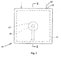
- a flat loudspeaker 10 includes a square peripheral frame 11 conveniently made of medium density fibreboard. Each external edge of the frame 11 is conveniently 400mm long. The frame is suspended by wires or cords 12 attached to loops or other fasteners 13 at the top of the frame 11.
- the front of the loudspeaker 10 is covered by a front diaphragm 14 which is attached and sealed around the edges thereof by a suitable adhesive to the front face of the frame 11.
- the rear of the loudspeaker 10 is covered by a rear diaphragm 15 attached and sealed to the rear face of the frame 11 by an adhesive.
- the interior of the loudspeaker 10 constitutes a sealed box.
- the thickness between the front and the rear faces of the diaphragm 14 are 30 millimetres for a 400 millimetres square loudspeaker.
- a suitable material for the front and rear diaphragms 14, 15 is a double skinned sheet made from a polypropylene copolymer approximately 3 millimetres thick and approximately 500 grams per square metre or less.
- the sheet is fluted, has a tensile strength of around 28 MPa or more and shore hardness of 67 or more.
- the material preferably has a corona discharge treated surface to assist adhesion of paint, or wallpaper to the exterior surfaces of the diaphragms 14, 15 and to assist adhesion of the interior surfaces of the diaphragms 14, 15 to the frame 11.
- the sheet is preferably a laminate having a core formed from ribs, tubes or corrugations, or the like.
- One such a material is known as "core flute” material from the shape of the internal longitudinal "flutes” or corrugations - see Figure 4 (discussed below).
- Another practical material is lightweight corrugated card.
- a driver unit 16 is positioned adjacent the centre of the diaphragms 14, 15.
- the driver unit is similar to those used in conventional cone-type loudspeakers and includes a magnet 17, which can be a permanent magnet or an electromagnet, and a coacting voice coil 18.
- the voice coil 18 carries the usual winding connected by leads 19 to terminals 20 on the rear of the loudspeaker 10.
- the magnet 17 is fastened, for example, by an adhesive to the interior surface of the rear diaphragm 15 and the voice coil 18 is fastened to the interior surface of the front diaphragm 14.
- the dimensions of the driver unit 16 and the spacing of the front and rear diaphragms 15, are arranged so that the voice coil 18 is in the correct operative position relative to the magnet 17, and properly centered therein.
- the interior thereof may be at least partly filled with fibrous or other sound absorbent material or may be left empty.
- one or more ports or vents may be provided through the frame 11 or the diaphragms 14, 15.
- the loudspeaker 10 has been shown as being square, it could be circular, elliptical, rectangular, polygonal or and other suitable shape. If required more than one driver unit 16 may be provided as suitable locations inside the loudspeaker 10.
- the front diaphragm 14 or the rear diaphragm 15 may be of substantially rigid material. Furthermore, the magnet 17 may be fitted to the front diaphragm 14 and the voice coil 18 to the rear diaphragm 15.
- two coaxial voice coils 18 each fastened to a different one of the diaphragms 14, 15 and coacting with a centrally suspended magnet 17.
- two magnets 17 can be provided on the diaphragms 14, 15 coacting with a centrally suspended voice coil 18.
- each diaphragm 14, 15 may be slightly fluted and instead of either diaphragm being flat, it could be corrugated or otherwise curved so as to provide a modified acoustic performance of the loudspeaker 10.
- the frame 11 and rear diaphragm 15 are omitted.
- the magnet 17 is mounted on a plate 21 which is mounted on the diaphragm 14 on pillars 22.
- the pillars 22 are at carefully selected positions on the diaphragm 14, so that they do not impede flexure of the diaphragm in one of its natural modes, for example as shown by the line 23.
- the magnet 17 may be mounted between the plate 21 and diaphragm 14, or on the rear of the plate 21, as shown.
- the loudspeaker shown in Figure 3 may be suspended from the top edge of the diaphragm 14 or from the plate 21 or pillars 22.
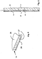
- Figure 4 shows a preferred construction for the front diaphragm 14. It comprises an integral extrusion of polyethylene around 3-5mm thick and having front and rear skins 25, 26 joined by continuous longitudinal walls 27 with air spaces therebetween.
- the material of the diaphragm 14 is anisotropic and has a longitudinal bending strength which may typically be around twice the transverse bending strength.
- this material is particularly useful in the construction of rectangular loudspeakers, for example those having sides of 200mm x 100mm long. Larger or smaller panels can be made using this type of material.
- Figure 5 shows a loudspeaker having a rigid rear panel 28 of custom wood around 12mm thick, with the magnet 17 fastened in the centre thereof.
- the frame 11 holds the front diaphragm 14 at a distance of around 3-5mm from the front face of the panel 28.
- the voice coil 18 is held in the gap in the magnet 17 by being fastened in a central hole in the diaphragm 14. The hole is closed by a concave part-spherical cap 29, fastened in the voice coil 18.
- the panel 28 (shown in figure 6) has an array of holes or ports 30 therethrough.
- the sizes and locations of the ports 30 are carefully chosen to achieve a smooth frequency response from the loudspeaker 10.
- Suitable material is bituminous sheet loaded with metallic or mineral particles.
- a loudspeaker 110 includes a diaphragm 111, to be described later.
- the outer edge of the diaphragm 111 is gripped by the outer edge of a substantially rigid metal or plastics dish 112.
- the dish is provided with a flat 113 on which the diaphragm 111 rests, the diaphragm 111 being located by a substantially upright wall 114 and being gripped by an edge portion 115 of the dish 112, which is folded or rolled over the outer edge of the diaphragm 111.
- the centre portion of the dish 112 is formed as a cup 116 in which a cylindrical yoke 117 is located.
- the dish 112 serves to centre the yoke 117 relative to the diaphragm 111, where it is retained by a screw 119.
- the yoke 117 forms part of a magnetic circuit, it is preferably made of low oxygen pure iron which has been annealed slowly in hydrogen.
- a permanent magnet 118 is held coaxial with the yoke 117 by adhesive.
- One pole of the magnet 118 is in magnetic contact with the upper interior surface of the yoke 117 and the other pole is adjacent a disc 135, of the same material and thickness as a flange 120 of the yoke 117.
- an annular magnetic gap 121 is formed between the flange 120 and the upper part of the magnet 118.
- a cylindrical voice coil 122 extends through the gap 121.
- the yoke material serves to keep the lines of magnetic flux within the yoke 117, which minimises undesirable external magnetic fields and also concentrates the flux across the gap 121.
- a panel 124 of thin material such as aluminium typically 0.25mm thick.
- the panel 124 has an out- turned flange 125 fastened to the diaphragm 111.
- the voice coil 122 is fastened by adhesive into a groove 126 formed in the panel 124, so that the voice coil 122 is held concentrically within the gap 121.
- Movement of the central area of the diaphragm 111 is damped by a damping ring 127 which may be of cloth or cloth-like material, is preferably corrugated and is fastened by adhesive to the upper surface of the flange 120 and to the flange 125 and/or the diaphragm 111.
- the dish 112 may form an airtight enclosure with the diaphragm 111 and panel 124, but if preferred, holes or perforations my be provided through the dish 112.
- the internal space within the loudspeaker 110 may include fibrous or foam plastics sound absorbent material.
- the thickness and material of the panel 124 are chosen so that, for example, at frequencies up to 1000 Hz the panel 124 acts as a substantially rigid member and moves the adjacent area of the diaphragm 111 therewith when alternating current is passed through windings 128 on the voice coil 122.
- frequencies above 5000 Hz flexure of the panel 124 is such that the periphery thereof and adjacent areas of the diaphragm 111 move much less than the voice coil 122 and the central area of the panel 124.
- sound is radiated almost entirely from the centre area of the panel 124. Between those frequencies sound radiation occurs from only a small area of the diaphragm 111 and from parts of the panel 124.
- the windings 128 may have more turns per unit length towards the ends of the winding 128 than in the centre thereof. This may be achieved by spacing the windings in the centre or by close-winding the turns throughout the length thereof and adding one or more layers 129 adjacent the ends thereof.
- the coils are wound on a former 136 provided with perforations 137.
- a suitable material for the diaphragms 111 is a double skinned sheet made from a polypropylene co-polymer approximately 3 millimetres thick and approximately 500 grams per square metre or less.
- the diaphragm 111 has a tensile strength of around 128 MPa or more and shore hardness of 67 or more.
- the material preferably has a corona discharge treated surface to assist adhesion of paint, wallpaper etc to the diaphragms 111.
- the diaphragm 111 is preferably a laminate having a core of foam, or has ribs, tubes, corrugated sheet or the like. If it has a foam core it preferable that the foam is not uniform (or the cover sheets are shaped or reinforced). For example the foam core could be shaped or reinforced in such a way that the bending stiffness is greater in one direction than another.
- the diaphragm 111 may comprise an integral extrusion of polyethylene around 3 to 5mm thick and having front and rear skins 130, 131 joined by continuous longitudinal walls 132 with air spaces therebetween.
- the material of the diaphragm 111 is anisotropic and has a longitudinal bending strength which may typically be around twice the transverse bending strength.
- this material is particularly useful in the construction of rectangular loudspeakers, for example those having sides of 200mm x 100mm long.
- Figure 8 shows the use of a retaining ring 138, of thin aluminium or the like.
- the ring 138 has a flange 139, which can press down on the external skin 130 of the diaphragm 111.
- An integral cylindrical portion 140 can be pushed down between the edge of the aperture 123 and the outside surface of the cylindrical part of the panel 124, which has a rib 142 which clicks into a groove 141 in the portion 140 of the ring 138.
- the rib 142 and groove 141 may be reversed, if preferred.
- This invention lends itself to flat panel speakers of A5 size or smaller which are particularly suited for the multimedia market, or for inclusion in vehicles fitted into dashboards or into vehicle doors.
- The can work in any orientation and depending upon design can be provided with or without a surrounding frame.
- One or more drivers may be used depending upon the size of the diaphragm.
- the loudspeakers may be tuned by porting or by adding weights.
- porting in the back panel (figures 6 and 7) but similar porting may be provided in the material of the diaphragm.
- the panels may be tuned by the use of a powder such as sugar or the like on the panel when horizontal so that the nodes can be observed on the panel.
- the diaphragms can be made of any shape (eg they could have irregular outlines if needed). They need not be flat although this is preferred.
- core flute or corrugated cardboard can be used.
- the material is light weight and stiff but flexible.
- standard extruded core flute of 3mm thickness has been used but other thicknesses between 2mm and 5mm could be used for most applications. Larger panels may require more drivers and a thicker core flute diaphragm.
- the loudspeaker could be disguised as part of a vehicle or part of furniture or a box or a painting or almost any object as size or shape is no longer a restriction.
- flat panel loudspeakers as part of a vehicle dashboard and in another application we have made a painting operate as a loudspeaker.
Landscapes
- Engineering & Computer Science (AREA)
- Multimedia (AREA)
- Physics & Mathematics (AREA)
- Acoustics & Sound (AREA)
- Signal Processing (AREA)
- Audible-Bandwidth Dynamoelectric Transducers Other Than Pickups (AREA)
- Diaphragms For Electromechanical Transducers (AREA)
- Chair Legs, Seat Parts, And Backrests (AREA)
- Liquid Crystal (AREA)
- Surgical Instruments (AREA)
Abstract
Description
- This invention relates to loudspeakers, and is applicable particularly, but not exclusively to loudspeakers intended to be hung adjacent a wall, in the manner of a picture.
- Flat loudspeakers have been known for many years, for example free-standing electrostatic loudspeakers. However, such loudspeakers have had to be large and therefore obtrusive in order to produce a satisfactory sound level. They have been expensive and have had a less than desirable sound frequency response and sound distribution pattern.
- Various other types of flat, wall-mountable loudspeakers have been devised such as shown in WO 97/09840, but again they have suffered variously from inferior frequency response or stereophonic performance.
- According to the present invention there is provided a loudspeaker comprising a substantially planar diaphragm which can be vibrated so as to radiate sound from at least a front face thereof and a driver unit operable by varying electric current in order to generate a varying force on the diaphragm, the force varying in a manner related to the varying electric current, the diaphragm comprising parallel membranes spaced apart by wall means which defines elongated passageways between the membranes generally parallel with the membranes and with one-another whereby the diaphragm has a bending stiffness longitudinally of said passageways greater than its bending stiffness transverse thereto.
- The dependent claims 2 to 28 refer to various preferred embodiments thereof.
- The wall means may comprise parallel walls or it may be a fluted structure of sinusoidal cross section.
- The diaphragm is preferably planar. It may be of non-metallic material and may be an extrusion of a plastics material, such as a polypropylene copolymer. The plastics material may be formed with a skin on opposite sides of the diaphragm.
- Preferably the diaphragm is approximately 500 grams or less per square metre and has a tensile strength of 28 Mpa or greater. Preferably it has a Shore hardness of 67 or more. It may be approximately 3 mm thick.
- External surfaces of the diaphragm may be treated with a corona discharge to assist adhesion.
- The loudspeaker may comprise a substantially rigid peripheral frame having a front face and a rear face, said first-mentioned diaphragm extending wholly across the front face and another diaphragm extending wholly across the rear face whereby the interior space of the loudspeaker is substantially enclosed. In this construction the driver unit may be connected to both of said diaphragms whereby the driver unit will apply varying force, corresponding to the varying electric current, to said diaphragms and cause at least one of said diaphragms to flex and emit an acoustic signal from the face of said one diaphragm external to the loudspeaker.
- A loudspeaker of this construction may constitute a sealed box. Alternatively one or more ports or vents may be provided through the frame or through one or both of the diaphragms.
- Both diaphragms may be flexible and the driver may operate the diaphragms in bi-polar mode, that is they may move outwards together and inwards together. Alternatively one of the diaphragms may be flexible and the other rigid.
- The driver unit may be mounted on a body connected to the diaphragm by pillars at positions selected so that flexure of the diaphragm in one or more of its natural modes of vibration is not impeded.
- The driver unit may comprise two coaxial voice coils each fastened to a different one of said diaphragms, the voice coils co-acting with a magnet suspended centrally between said voice coils.
- Alternatively the driver unit may include a magnet one pole of which is in magnetic continuity with a yoke and the other pole of which is positioned from the yoke by an air gap through which gap a voice coil is operable, the voice coil being attached to drive said first-mentioned diaphragm, the yoke being made from low oxygen pure iron annealed very slowly in hydrogen.
- The magnet may be a cylindrical permanent magnet and the yoke may be coaxial therewith, the air gap being annular. The magnet may be a high strength permanent magnet such as a neodymium magnet.
- A member made of the same material as the yoke may be in magnetic continuity with said other pole of the magnet, the air gap being formed between a peripheral portion of said member and an opposing part of the yoke. Said peripheral portion of the member and said opposing part of the yoke may be of substantially the same thickness.
- Preferably the voice coil has more windings per unit length thereof away from that axial part of the voice coil which is in said air gap when no electric current is passed through the windings.
- The voice coil winding may be a single layer with the windings spaced apart in the region of said axial part. The voice coil may be of pure copper or of aluminium wire. More than said single layer may be wound at regions of the voice coil further from said axial part.
- The voice coil may be connected to said first-mentioned diaphragm by means of a panel of material and having dimensions such that at a low range of audio frequencies the voice coil and at least that part of said diaphragm adjacent the panel move substantially at the same amplitude and phase, while at a higher range of audio frequencies at least said part of said diaphragm and a part of the panel adjacent thereto move at a lower amplitude and/or at a different phase from the voice coil, whereby at said higher range a substantial part of the sound emitted by the loudspeaker is radiated from a face of the panel adjacent the voice coil.
- A sheet of damping material may be connected from a stationary part of the loudspeaker to said part of the diaphragm adjacent the panel or to the panel, the damping material being porous or perforated so as to allow the passage of air therethrough. The damping material may be cloth or cloth based.
- Embodiments of the invention will now be described, by way of example only, with reference to the accompanying drawings, in which:
- Figure 1 is a front view of a loudspeaker according to the invention;
- Figure 2 is a cross-section in a vertical plane along the line II-II in Figure 1;
- Figure 3 shows a rear and side views of an alternative embodiment,
- Figure 4 is a partial perspective view of a component of the loudspeaker,
- Figure 5 is a cross-section of a further embodiment,
- Figure 6 is a first rear view of the embodiment shown in Figure 5, and
- Figure 7 is a second modified rear view of the component shown in Figure 4.
- Figure 8 is a transverse section through another embodiment.
- Figure 9 is a side view of a voice coil shown in section in Figure 8.
-
- In the drawings, a
flat loudspeaker 10 includes a squareperipheral frame 11 conveniently made of medium density fibreboard. Each external edge of theframe 11 is conveniently 400mm long. The frame is suspended by wires orcords 12 attached to loops orother fasteners 13 at the top of theframe 11. - As seen, particularly in Figure 2, the front of the
loudspeaker 10 is covered by afront diaphragm 14 which is attached and sealed around the edges thereof by a suitable adhesive to the front face of theframe 11. Similarly the rear of theloudspeaker 10 is covered by arear diaphragm 15 attached and sealed to the rear face of theframe 11 by an adhesive. Thus, the interior of theloudspeaker 10 constitutes a sealed box. Typically, the thickness between the front and the rear faces of thediaphragm 14 are 30 millimetres for a 400 millimetres square loudspeaker. - It has been found that a suitable material for the front and
rear diaphragms diaphragms diaphragms frame 11. The sheet is preferably a laminate having a core formed from ribs, tubes or corrugations, or the like. One such a material is known as "core flute" material from the shape of the internal longitudinal "flutes" or corrugations - see Figure 4 (discussed below). Another practical material is lightweight corrugated card. - A
driver unit 16 is positioned adjacent the centre of thediaphragms magnet 17, which can be a permanent magnet or an electromagnet, and acoacting voice coil 18. Thevoice coil 18 carries the usual winding connected byleads 19 toterminals 20 on the rear of theloudspeaker 10. Themagnet 17 is fastened, for example, by an adhesive to the interior surface of therear diaphragm 15 and thevoice coil 18 is fastened to the interior surface of thefront diaphragm 14. The dimensions of thedriver unit 16 and the spacing of the front andrear diaphragms 15, are arranged so that thevoice coil 18 is in the correct operative position relative to themagnet 17, and properly centered therein. - Depending on the acoustic properties required from the
loudspeaker 10, the interior thereof may be at least partly filled with fibrous or other sound absorbent material or may be left empty. Similarly, one or more ports or vents may be provided through theframe 11 or thediaphragms - Although the
loudspeaker 10 has been shown as being square, it could be circular, elliptical, rectangular, polygonal or and other suitable shape. If required more than onedriver unit 16 may be provided as suitable locations inside theloudspeaker 10. - In another embodiment, the
front diaphragm 14 or therear diaphragm 15 may be of substantially rigid material. Furthermore, themagnet 17 may be fitted to thefront diaphragm 14 and thevoice coil 18 to therear diaphragm 15. - For some purposes it may be preferable to provide two coaxial voice coils 18 each fastened to a different one of the
diaphragms magnet 17. Conversely, twomagnets 17 can be provided on thediaphragms voice coil 18. - Either surface of each
diaphragm loudspeaker 10. - In figure 3 the
frame 11 andrear diaphragm 15 are omitted. Themagnet 17 is mounted on aplate 21 which is mounted on thediaphragm 14 onpillars 22. Thepillars 22 are at carefully selected positions on thediaphragm 14, so that they do not impede flexure of the diaphragm in one of its natural modes, for example as shown by theline 23. Themagnet 17 may be mounted between theplate 21 anddiaphragm 14, or on the rear of theplate 21, as shown. - The loudspeaker shown in Figure 3 may be suspended from the top edge of the
diaphragm 14 or from theplate 21 orpillars 22. - Figure 4 shows a preferred construction for the
front diaphragm 14. It comprises an integral extrusion of polyethylene around 3-5mm thick and having front andrear skins longitudinal walls 27 with air spaces therebetween. By this construction, the material of thediaphragm 14 is anisotropic and has a longitudinal bending strength which may typically be around twice the transverse bending strength. Thus, this material is particularly useful in the construction of rectangular loudspeakers, for example those having sides of 200mm x 100mm long. Larger or smaller panels can be made using this type of material. - Figure 5 shows a loudspeaker having a rigid
rear panel 28 of custom wood around 12mm thick, with themagnet 17 fastened in the centre thereof. Theframe 11 holds thefront diaphragm 14 at a distance of around 3-5mm from the front face of thepanel 28. Thevoice coil 18 is held in the gap in themagnet 17 by being fastened in a central hole in thediaphragm 14. The hole is closed by a concave part-spherical cap 29, fastened in thevoice coil 18. - In order to allow desired motion of the
diaphragm 14, the panel 28 (shown in figure 6) has an array of holes orports 30 therethrough. The sizes and locations of theports 30 are carefully chosen to achieve a smooth frequency response from theloudspeaker 10. - Alternative, or additional modification of the frequency response curve is achieved by adhesion of
mass adding material 31, as shown in Figure 7. Suitable material is bituminous sheet loaded with metallic or mineral particles. - Further adjustment of frequency performance can be obtained by attaching areas of sound
absorbent material 32 to thediaphragm 14 or to the front face of thepanel 28, as shown in Figure 7. Supply of electrical signal to thevoice coil 18 is conveniently through copper foil strips stuck to one face of thediaphragm 14. - In Figures 8 and 9, a
loudspeaker 110 includes adiaphragm 111, to be described later. The outer edge of thediaphragm 111 is gripped by the outer edge of a substantially rigid metal or plastics dish 112. For this purpose, the dish is provided with a flat 113 on which thediaphragm 111 rests, thediaphragm 111 being located by a substantiallyupright wall 114 and being gripped by anedge portion 115 of thedish 112, which is folded or rolled over the outer edge of thediaphragm 111. The centre portion of thedish 112 is formed as acup 116 in which acylindrical yoke 117 is located. Thus, thedish 112 serves to centre theyoke 117 relative to thediaphragm 111, where it is retained by ascrew 119. - Since the
yoke 117 forms part of a magnetic circuit, it is preferably made of low oxygen pure iron which has been annealed slowly in hydrogen. Apermanent magnet 118 is held coaxial with theyoke 117 by adhesive. One pole of themagnet 118 is in magnetic contact with the upper interior surface of theyoke 117 and the other pole is adjacent adisc 135, of the same material and thickness as aflange 120 of theyoke 117. Thus, an annularmagnetic gap 121 is formed between theflange 120 and the upper part of themagnet 118. Acylindrical voice coil 122 extends through thegap 121. The yoke material serves to keep the lines of magnetic flux within theyoke 117, which minimises undesirable external magnetic fields and also concentrates the flux across thegap 121. - In an
aperture 123 through thediaphragm 111, there is positioned and fastened apanel 124 of thin material, such as aluminium typically 0.25mm thick. Thepanel 124 has an out- turnedflange 125 fastened to thediaphragm 111. Thevoice coil 122 is fastened by adhesive into agroove 126 formed in thepanel 124, so that thevoice coil 122 is held concentrically within thegap 121. Movement of the central area of thediaphragm 111 is damped by a dampingring 127 which may be of cloth or cloth-like material, is preferably corrugated and is fastened by adhesive to the upper surface of theflange 120 and to theflange 125 and/or thediaphragm 111. - The
dish 112 may form an airtight enclosure with thediaphragm 111 andpanel 124, but if preferred, holes or perforations my be provided through thedish 112. The internal space within theloudspeaker 110 may include fibrous or foam plastics sound absorbent material. The thickness and material of thepanel 124 are chosen so that, for example, at frequencies up to 1000 Hz thepanel 124 acts as a substantially rigid member and moves the adjacent area of thediaphragm 111 therewith when alternating current is passed throughwindings 128 on thevoice coil 122. At frequencies above 5000 Hz flexure of thepanel 124 is such that the periphery thereof and adjacent areas of thediaphragm 111 move much less than thevoice coil 122 and the central area of thepanel 124. Thus, at these high frequencies sound is radiated almost entirely from the centre area of thepanel 124. Between those frequencies sound radiation occurs from only a small area of thediaphragm 111 and from parts of thepanel 124. - In order to modify the frequency response of the
loud speaker 110 at large excursions of thevoice coil 122, thewindings 128 may have more turns per unit length towards the ends of the winding 128 than in the centre thereof. This may be achieved by spacing the windings in the centre or by close-winding the turns throughout the length thereof and adding one ormore layers 129 adjacent the ends thereof. The coils are wound on a former 136 provided withperforations 137. - It has been found that a suitable material for the
diaphragms 111 is a double skinned sheet made from a polypropylene co-polymer approximately 3 millimetres thick and approximately 500 grams per square metre or less. Preferably thediaphragm 111 has a tensile strength of around 128 MPa or more and shore hardness of 67 or more. The material preferably has a corona discharge treated surface to assist adhesion of paint, wallpaper etc to thediaphragms 111. Thediaphragm 111 is preferably a laminate having a core of foam, or has ribs, tubes, corrugated sheet or the like. If it has a foam core it preferable that the foam is not uniform (or the cover sheets are shaped or reinforced). For example the foam core could be shaped or reinforced in such a way that the bending stiffness is greater in one direction than another. - The
diaphragm 111 may comprise an integral extrusion of polyethylene around 3 to 5mm thick and having front andrear skins longitudinal walls 132 with air spaces therebetween. By this construction, the material of thediaphragm 111 is anisotropic and has a longitudinal bending strength which may typically be around twice the transverse bending strength. Thus, this material is particularly useful in the construction of rectangular loudspeakers, for example those having sides of 200mm x 100mm long. - Figure 8 shows the use of a retaining
ring 138, of thin aluminium or the like. Thering 138 has aflange 139, which can press down on theexternal skin 130 of thediaphragm 111. An integralcylindrical portion 140 can be pushed down between the edge of theaperture 123 and the outside surface of the cylindrical part of thepanel 124, which has arib 142 which clicks into agroove 141 in theportion 140 of thering 138. Therib 142 and groove 141 may be reversed, if preferred. -
- Ease of manufacture.
- Good acoustics achievable at a low cost of construction.
- Lightweight diaphragm material particularly suite to rectangular or elliptical panels.
- Scalability.
- Loudspeakers or diaphragms can be made in many different sizes or shapes, or readily disguised as other objects.
-
- This invention lends itself to flat panel speakers of A5 size or smaller which are particularly suited for the multimedia market, or for inclusion in vehicles fitted into dashboards or into vehicle doors. The can work in any orientation and depending upon design can be provided with or without a surrounding frame.
- One or more drivers may be used depending upon the size of the diaphragm. The loudspeakers may be tuned by porting or by adding weights. In the drawings we have show porting in the back panel (figures 6 and 7) but similar porting may be provided in the material of the diaphragm. The panels may be tuned by the use of a powder such as sugar or the like on the panel when horizontal so that the nodes can be observed on the panel.
- The diaphragms can be made of any shape (eg they could have irregular outlines if needed). They need not be flat although this is preferred.
- Materials other than core flute or corrugated cardboard can be used. Preferably the material is light weight and stiff but flexible. In the preferred embodiments standard extruded core flute of 3mm thickness has been used but other thicknesses between 2mm and 5mm could be used for most applications. Larger panels may require more drivers and a thicker core flute diaphragm.
- The loudspeaker could be disguised as part of a vehicle or part of furniture or a box or a painting or almost any object as size or shape is no longer a restriction. In one example we have included flat panel loudspeakers as part of a vehicle dashboard and in another application we have made a painting operate as a loudspeaker.
- Finally various other alterations or modifications may be made to the foregoing without departing from the scope of this invention as set forth in the following claims.
Claims (28)
- A loudspeaker (10;110) comprising a substantially planar diaphragm (14; 111) which can be vibrated so as to radiate sound from at least a front face thereof and a driver unit (16) operable by varying electric current in order to generate a varying force on the diaphragm (14; 111), the force varying in a manner related to the varying electric current,
characterised in that the diaphragm (14; 111) comprises parallel membranes (25,26; 130,131) spaced apart by wall means (27; 132) which defines elongated passageways between the membranes (25,26; 130,131) generally parallel with the membranes (25,26; 130,131) and with one another whereby the diaphragm (14; 111) has a bending stiffness longitudinally of said passageways greater than its bending stiffness transverse thereto. - A loudspeaker (10; 110) as claimed in claim 1, characterised in that the wall means (27; 132) comprises parallel walls.
- A loudspeaker (10; 110) as claimed in claim 1, characterised in that the wall means (27; 132) is a fluted structure of sinusoidal cross section.
- A loudspeaker (10; 110) as claimed in any one of the preceding claims, characterised in that the diaphragm (14; 111) is of substantially rigid material.
- A loudspeaker (10; 110) as claimed in any one of the preceding claims, characterised in that the diaphragm is a one piece extrusion of a plastics material.
- A loudspeaker (10; 110) as claimed in claim 5 characterised in that the plastics material is a polypropylene copolymer.
- A loudspeaker as claimed in claim 6 characterised in that the plastics material is formed with a skin (25,25; 130,131) on opposite sides of the diaphragm (14; 111).
- A loudspeaker (10; 110) as claimed in claim 6 characterised in that the plastics material is core flute.
- A loudspeaker (10; 110) as claimed in any one of claims 1 to 5 characterised in that the diaphragm (14; 111) has a core formed from corrugations.
- A loudspeaker (10; 110) as claimed in any one of claims 1 to 5 characterised in that the diaphragm (14; 111) is of corrugated card.
- A loudspeaker (10; 110) as claimed in claim 10 characterised in that the diaphragm (14; 111) is of lightweight corrugated cardboard.
- A loudspeaker (10; 110) as claimed in any one of claims 1 to 4 characterised in that the diaphragm (14; 111) consists of a material selected from the group consisting of core flute plastics, lightweight corrugated cardboard and fluted laminated plastics
- A loudspeaker (10; 110) as claimed in any preceding claim, characterised in that the diaphragm (14; 111) is approximately 500 grams or less per square metre.
- A loudspeaker (10; 110) as claimed in any one of the preceding claims characterised in that the diaphragm (14; 111) has a tensile strength of 28 Mpa or greater.
- A loudspeaker (10; 110) as claimed in any one of the preceding claims characterised in that the diaphragm (14; 111) has a Shore hardness of 67 or more.
- A loudspeaker (10; 110) as claimed in any preceding claim characterised in that external surfaces (25,26; 130,131) of the diaphragm (14; 111) are treated with a corona discharge to assist adhesion.
- A loudspeaker (10; 110) as claimed in any one of the preceding claims characterised in that it comprises a substantially rigid peripheral frame (11) having a front face and a rear face, said first mentioned diaphragm (14; 111) extending wholly across the front face and another diaphragm (15) extending wholly across the rear face whereby the interior space of the loudspeaker (10; 110) is substantially enclosed.
- A loudspeaker (10; 110) as claimed in claim 17 characterised in that the driver unit (16) is connected to both of said diaphragms (14;111; 15) whereby the driver unit (16) will apply varying force, corresponding to the varying electric current, to said diaphragms (14;111; 15) and cause at least one of said diaphragms (14;111; 15) to flex and emit an acoustic signal from the face of said one diaphragm (14; 111) external to the loudspeaker (10; 110).
- A loudspeaker (10; 110) as claimed in claim 17 characterised in that the driver unit (16) comprises two coaxial voice coils (18; 122) each fastened to a different one of said diaphragms (14;111 15), the voice coils (18; 122) co-acting with a magnet (17; 118) suspended centrally between said voice coils (18; 122).
- A loudspeaker (10; 110) as claimed in any one of claims 1 to 16 characterised in that the driver unit (16) includes a magnet (17; 118) one pole of which is in magnetic continuity with a yoke (117) and the other pole of which is positioned from the yoke (117) by an air gap (121) through which gap a voice coil (18; 122) is operable, the voice coil (18; 122) being attached to drive said diaphragm (111), the yoke (117) being made from low oxygen pure iron annealed very slowly in hydrogen.
- A loudspeaker (10; 110) as claimed in claim 20 characterised in that a member made of the same material as the yoke (117) is in magnetic continuity with said other pole of the magnet (17; 118), the air gap (121) being formed between a peripheral portion of said member (135) and an opposing part of the yoke (117).
- A loudspeaker (10; 110) as claimed in claim 21 characterised in that said peripheral portion of the member (135) and said opposing part of the yoke (117) are of substantially the same thickness.
- A loudspeaker (10; 110) as claimed in any one of claims 17 to 22 characterised in that the voice coil (18; 122) has more windings (128) per unit length thereof away from that axial part of the voice coil (18; 122) which is in said air gap (12) when no electric current is passed through the windings (128).
- A loudspeaker (10; 110) as claimed in claims 17 to 22, characterised in that the voice coil (17; 122) winding is a single layer with the windings (128) spaced part in the region of said axial part.
- A loudspeaker (10; 110) as claimed in claim 24 characterised in that more than said single layer is wound at regions of the voice coil (18; 122) further from said axial part.
- A loudspeaker (10; 110) as claimed in any one of claims 17 to 25 characterised in that the voice coil (18; 122) is connected to said the diaphragm (14, 111) by means of a panel (124) of material and having dimensions such that at a low range of audio frequencies the voice coil (18; 122) and at least that part of said diaphragm (14; 111) adjacent the panel (124) move substantially at the same amplitude and phase, while at a higher range of audio frequencies at least said part of said diaphragm (14; 111) and a part of the panel (124) adjacent thereto move at a lower amplitude and/or at a different phase from the voice coil (18; 122) whereby at said higher range a substantial part of the sound emitted by the loudspeaker (10; 110) is radiated from a face of the panel (124) adjacent the voice coil (18; 122).
- A loudspeaker (10, 110) as claimed in claim 26 characterised in that a sheet of damping material (127) is connected from a stationary part of the loudspeaker (10; 110) to said part of the diaphragm (14; 111) adjacent the panel (124) or to the panel (124), the damping material being porous or perforated so as to allow the passage of air therethrough.
- A loudspeaker (10; 110) as claimed in claim 27 characterised in that the damping material (127) is cloth or cloth based.
Applications Claiming Priority (7)
| Application Number | Priority Date | Filing Date | Title |
|---|---|---|---|
| NZ330777A NZ330777A (en) | 1998-06-22 | 1998-06-22 | Loudspeaker with a planar diaphragm having a bending strength along one axis which is greater that along a second axis perpendicular to the first axis |
| NZ33077798 | 1998-06-22 | ||
| NZ33232898 | 1998-10-13 | ||
| NZ33232898 | 1998-10-13 | ||
| NZ33383399 | 1999-01-21 | ||
| NZ33383399 | 1999-01-21 | ||
| PCT/NZ1999/000088 WO1999067974A1 (en) | 1998-06-22 | 1999-06-18 | Loudspeakers |
Publications (3)
| Publication Number | Publication Date |
|---|---|
| EP1120007A1 EP1120007A1 (en) | 2001-08-01 |
| EP1120007A4 EP1120007A4 (en) | 2002-01-23 |
| EP1120007B1 true EP1120007B1 (en) | 2005-08-24 |
Family
ID=27353857
Family Applications (1)
| Application Number | Title | Priority Date | Filing Date |
|---|---|---|---|
| EP99928261A Expired - Lifetime EP1120007B1 (en) | 1998-06-22 | 1999-06-18 | Loudspeakers |
Country Status (19)
| Country | Link |
|---|---|
| US (1) | US6411723B1 (en) |
| EP (1) | EP1120007B1 (en) |
| AT (1) | ATE303051T1 (en) |
| AU (1) | AU756783B2 (en) |
| CA (1) | CA2336072A1 (en) |
| CZ (1) | CZ20004748A3 (en) |
| DE (1) | DE29923450U1 (en) |
| DK (1) | DK1120007T3 (en) |
| ES (1) | ES2251198T3 (en) |
| FI (1) | FI20002715A7 (en) |
| GB (1) | GB2351868B (en) |
| HU (1) | HUP0102904A3 (en) |
| ID (1) | ID27400A (en) |
| IL (1) | IL140304A0 (en) |
| NO (1) | NO20006558L (en) |
| PL (1) | PL191378B1 (en) |
| RO (1) | RO121307B1 (en) |
| TR (1) | TR200003739T2 (en) |
| WO (1) | WO1999067974A1 (en) |
Families Citing this family (32)
| Publication number | Priority date | Publication date | Assignee | Title |
|---|---|---|---|---|
| DE19939409C2 (en) * | 1999-08-20 | 2002-03-21 | L & B Lautsprecher Und Beschal | Sound converter for wall and ceiling installation |
| US6590993B2 (en) | 1999-09-06 | 2003-07-08 | Koninklijke Philips Electronics N.V. | Panel-shaped loudspeaker |
| DE19944802C2 (en) * | 1999-09-20 | 2003-08-28 | Harman Audio Electronic Sys | door |
| GB9928456D0 (en) * | 1999-12-02 | 2000-01-26 | New Transducers Ltd | Loudspeakers |
| JP3720242B2 (en) * | 2000-01-17 | 2005-11-24 | 桂子 武藤 | Planar type loudspeaker |
| US20010031052A1 (en) * | 2000-03-07 | 2001-10-18 | Lock Christopher Colin | Noise suppression loudspeaker |
| US7155021B2 (en) | 2000-05-08 | 2006-12-26 | Koninklijke Philips Electronics N.V. | Loudspeaker having an acoustic panel and an electrical driver |
| US8103024B2 (en) * | 2000-09-20 | 2012-01-24 | Harman Becker Automotive Systems Gmbh | Door with structural components configured to radiate acoustic energy |
| US20030133581A1 (en) * | 2002-01-07 | 2003-07-17 | Klayman Arnold I. | User configurable multi-component speaker panel |
| US7123737B2 (en) * | 2002-02-13 | 2006-10-17 | Plantronics, Inc. | Ear clasp headset |
| JP3984108B2 (en) * | 2002-06-07 | 2007-10-03 | 富士通テン株式会社 | Speaker |
| US6870941B2 (en) * | 2002-07-15 | 2005-03-22 | Glenn A. Marnie | Dipole radiating dynamic speaker |
| GB0221503D0 (en) * | 2002-09-17 | 2002-10-23 | 1 Ltd | Loudspeaker |
| US6929091B2 (en) * | 2002-10-28 | 2005-08-16 | Sound Advance Systems, Inc. | Planar diaphragm loudspeaker and related methods |
| JP2004260346A (en) * | 2003-02-24 | 2004-09-16 | Alps Electric Co Ltd | Electroacoustic transducer |
| US6980931B1 (en) * | 2003-04-03 | 2005-12-27 | Reitano Carmen T | System and method for controlling computer processes by means of biometric data |
| US7508953B2 (en) * | 2003-12-30 | 2009-03-24 | Audio Products International Corp. | Loudspeaker and components for use in construction thereof |
| EP1558057A1 (en) * | 2004-01-23 | 2005-07-27 | DE ROOIJ, Jacobus, Maria | Loudspeaker with specific plastic element for sound emission |
| US7510047B2 (en) * | 2004-03-05 | 2009-03-31 | Keiko Muto | Speaker edge and resonator panel assembly |
| US20050194203A1 (en) * | 2004-03-05 | 2005-09-08 | Keiko Muto | Planar speaker edge |
| DE102004048990A1 (en) * | 2004-10-04 | 2006-04-06 | Volkswagen Ag | Speaker arrangement in a motor vehicle |
| US7607512B2 (en) * | 2005-08-23 | 2009-10-27 | Ronald Paul Harwood | Speaker assembly for a structural pole and a method for mounting same |
| US20070064964A1 (en) * | 2005-09-16 | 2007-03-22 | Cheung Kwun-Wing W | Flat panel speaker assembly |
| KR100745664B1 (en) | 2006-02-01 | 2007-08-02 | 크레신 주식회사 | speaker |
| EP2458893B1 (en) * | 2010-11-26 | 2015-11-25 | Knowles Ipc (M) Sdn Bhd | Loudspeaker |
| DE202011050962U1 (en) * | 2011-08-11 | 2012-11-15 | Halemeier Gmbh & Co. Kg | Arrangement for reproducing audio signals |
| DE102011084168B4 (en) | 2011-10-07 | 2020-07-09 | Röchling Automotive AG & Co. KG | Flexible shaft loudspeaker, motor vehicle with flexible shaft loudspeaker, and use of a flexible shaft loudspeaker |
| DE102012108258A1 (en) * | 2012-09-05 | 2014-03-06 | Pursonic Gmbh | Method for producing a flat-panel loudspeaker |
| US9961449B2 (en) | 2014-10-15 | 2018-05-01 | Panasonic Intellectual Property Management Co., Ltd. | Loudspeaker and mobile body device having loudspeaker mounted thereon |
| DE202015101129U1 (en) * | 2015-03-06 | 2016-06-08 | LEGIS GbR (vertretungsberechtigter Gesellschafter: Thomas C.O. Schmidt, 10707 Berlin) | Flat membrane with resin filled holes, planar speakers with flat membrane and acoustic unit with such a planar loudspeaker |
| US9877112B2 (en) * | 2016-03-29 | 2018-01-23 | Dell Products L.P. | Piezoelectric force actuator audio system |
| DE102019109618B3 (en) * | 2019-04-11 | 2020-08-13 | Konrad Gießibl | Wooden soundplate |
Family Cites Families (111)
| Publication number | Priority date | Publication date | Assignee | Title |
|---|---|---|---|---|
| US1768473A (en) | 1930-06-24 | Sound-propagating diaphragm | ||
| US1273549A (en) | 1916-10-25 | 1918-07-23 | Thomas Sloper | Hydroaeroplane. |
| US6181799B1 (en) | 1995-09-02 | 2001-01-30 | New Transducers Limited | Greetings or the like card |
| US1500331A (en) | 1922-07-20 | 1924-07-08 | Robert H Marriott | Telephonic receiver |
| GB290710A (en) | 1927-02-12 | 1928-05-14 | Joseph Harrison Thomson Robert | Improvements in or relating to diaphragms for loudspeakers and like sound-reproducing devices |
| GB320654A (en) | 1928-04-21 | 1929-10-21 | George Rex Searle | Improvements in loud speakers for wireless apparatus or the like |
| US1778084A (en) | 1928-09-26 | 1930-10-14 | James V Nevin | Screen loud-speaker |
| GB323539A (en) | 1928-10-04 | 1930-01-06 | George Rex Searle | Improvements in or relating to diaphragms for loud-speakers and like instruments |
| US2063945A (en) | 1933-08-02 | 1936-12-15 | Pierce George Washington | Diaphragm and method |
| USRE24141E (en) | 1952-10-25 | 1956-04-10 | Method of making the same | |
| US2815823A (en) | 1953-03-02 | 1957-12-10 | Rca Corp | Loudspeaker structure |
| US2863520A (en) | 1955-03-11 | 1958-12-09 | Gen Dynamics Corp | Loudspeaker cone rim treatment |
| US2956538A (en) | 1957-12-10 | 1960-10-18 | Gen Ultrasonics Company | Diaphragm vibration control |
| US3111187A (en) | 1959-11-23 | 1963-11-19 | H J Leak & Company Ltd | Diaphragm for electro acoustic transducer |
| US3247925A (en) | 1962-03-08 | 1966-04-26 | Lord Corp | Loudspeaker |
| DE1132593B (en) | 1965-04-05 | 1962-07-05 | Bolt Beranek & Newman | Acoustically effective plate, especially for coupling to an electroacoustic transducer |
| US3603427A (en) | 1968-11-19 | 1971-09-07 | Nippon Musical Instruments Mfg | Loudspeaker |
| US3578921A (en) * | 1970-01-26 | 1971-05-18 | Sonotone Corp | Miniature multiple-diaphragm acoustic mechanoelectric transducer device |
| FR2137567B1 (en) | 1971-05-07 | 1977-08-26 | Rank Organisation Ltd | |
| AR192576A1 (en) | 1971-06-16 | 1973-02-28 | Bertagni J | A DIAPHRAGM FOR FLAT SPEAKERS TO ACCENTUATE LOW FREQUENCIES AND CHANGE THE RINGER AND SOUND COLOR |
| US3848090A (en) | 1971-11-18 | 1974-11-12 | J Walker | Wall hanging speaker system |
| US4013846A (en) | 1975-08-28 | 1977-03-22 | Minnesota Mining And Manufacturing Company | Piston loudspeaker |
| GB1563511A (en) | 1976-03-19 | 1980-03-26 | Harwood H | Diaphragms for electroacoustic transducers |
| JPS5748153Y2 (en) * | 1977-11-26 | 1982-10-22 | ||
| JPS603277B2 (en) | 1978-06-15 | 1985-01-26 | ソニー株式会社 | speaker device |
| JPS5525285A (en) | 1978-08-14 | 1980-02-22 | Sony Corp | Speaker |
| JPS5541066A (en) | 1978-09-19 | 1980-03-22 | Sony Corp | Diaphragm for electroacoustic converter |
| JPS5568795A (en) | 1978-11-20 | 1980-05-23 | Sony Corp | Speaker |
| US4225757A (en) | 1978-12-18 | 1980-09-30 | Babbco, Ltd. | Broad band dynamic loudspeaker |
| JPS55161496A (en) * | 1979-05-31 | 1980-12-16 | Matsushita Electric Ind Co Ltd | Diaphragm for speaker and its production |
| US4352961A (en) | 1979-06-15 | 1982-10-05 | Hitachi, Ltd. | Transparent flat panel piezoelectric speaker |
| DE3024728C2 (en) | 1979-06-30 | 1982-12-23 | Pioneer Electronic Corp., Tokyo | Driver device for a loudspeaker arrangement |
| NL7908896A (en) * | 1979-12-11 | 1981-07-01 | Philips Nv | A MECHANICAL FILTER FOR AN ELECTRODYNAMIC CONVERTER. |
| US4426556A (en) | 1980-07-08 | 1984-01-17 | Matsushita Electric Industrial Co., Ltd. | Electrodynamic loudspeaker |
| US4385210A (en) | 1980-09-19 | 1983-05-24 | Electro-Magnetic Corporation | Electro-acoustic planar transducer |
| DE3172790D1 (en) * | 1980-12-19 | 1985-12-05 | Nissan Motor | Speaker for automotive vehicle audio system |
| NL8200690A (en) * | 1982-02-22 | 1983-09-16 | Philips Nv | SPEAKER MEMBRANE CONTAINING A LAYER OF POLYMETHACRYLIMIDE FOAM. |
| JPS58200694A (en) | 1982-05-18 | 1983-11-22 | Matsushita Electric Ind Co Ltd | Diaphragm for speaker |
| JPS59139799A (en) | 1983-01-31 | 1984-08-10 | Sony Corp | Flat speaker |
| US4550228A (en) * | 1983-02-22 | 1985-10-29 | Apogee Acoustics, Inc. | Ribbon speaker system |
| JPS60192497A (en) | 1984-03-14 | 1985-09-30 | Mitsubishi Electric Corp | Speaker |
| JPS6121699A (en) * | 1984-07-10 | 1986-01-30 | Pioneer Electronic Corp | Electric vibrating transducer |
| JPS6175696U (en) | 1984-10-23 | 1986-05-21 | ||
| JPS61113399A (en) | 1984-11-08 | 1986-05-31 | Matsushita Electric Ind Co Ltd | flat speaker |
| JPS62207100A (en) | 1986-03-07 | 1987-09-11 | Matsushita Electric Ind Co Ltd | flat speaker |
| JPS62269500A (en) | 1986-05-16 | 1987-11-21 | Matsushita Electric Ind Co Ltd | flat speaker unit |
| US4899390A (en) | 1986-09-19 | 1990-02-06 | Matsushita Electric Industrial Co., Ltd. | Thin speaker having an enclosure within an open portion and a closed portion |
| JP2558667B2 (en) | 1986-12-19 | 1996-11-27 | 松下電器産業株式会社 | Rectangular flat speaker |
| JPS63254896A (en) | 1987-04-10 | 1988-10-21 | Matsushita Electric Ind Co Ltd | flat speaker |
| CA1284837C (en) * | 1987-06-18 | 1991-06-11 | Highwood Audio Inc. | Audio transducer |
| JPS6427399A (en) | 1987-07-23 | 1989-01-30 | Matsushita Electric Industrial Co Ltd | Rectangular flat speaker |
| US5025474A (en) | 1987-09-29 | 1991-06-18 | Matsushita Electric Industrial Co., Ltd. | Speaker system with image projection screen |
| JPH01229600A (en) | 1988-03-09 | 1989-09-13 | Sumitomo Rubber Ind Ltd | Speaker diaphragm |
| JPH02170795A (en) * | 1988-12-23 | 1990-07-02 | Foster Electric Co Ltd | Panel type loudspeaker |
| US4997058A (en) | 1989-10-02 | 1991-03-05 | Bertagni Jose J | Sound transducer |
| ATE117155T1 (en) | 1990-08-04 | 1995-01-15 | Secr Defence Brit | PANEL-SHAPED SPEAKER. |
| GB2246684A (en) | 1990-08-04 | 1992-02-05 | Secr Defence | Panel form loudspeaker |
| JPH04115698A (en) | 1990-08-31 | 1992-04-16 | Matsushita Electric Ind Co Ltd | Flat speaker |
| US5343443A (en) * | 1990-10-15 | 1994-08-30 | Rowe, Deines Instruments, Inc. | Broadband acoustic transducer |
| JPH04150700A (en) | 1990-10-15 | 1992-05-25 | Murata Mfg Co Ltd | Panel speaker |
| US5231672A (en) * | 1991-07-10 | 1993-07-27 | Tsao Ye Ming | Plane-surfaced waved out-diffusion triangular beam-typed resonant board |
| US5425107A (en) * | 1992-04-09 | 1995-06-13 | Bertagni Electronic Sound Transducers, International Corporation | Planar-type loudspeaker with dual density diaphragm |
| GB9317345D0 (en) | 1993-08-20 | 1993-10-06 | Centralforce Ltd | Loudspeaker |
| KR970002298Y1 (en) * | 1994-04-29 | 1997-03-21 | 김경우 | Multi-con speaker |
| US5701359A (en) * | 1995-04-06 | 1997-12-23 | Precision Power | Flat-panel speaker |
| ES2130845T3 (en) | 1995-09-02 | 1999-07-01 | New Transducers Ltd | DISPLAY SCREENS INCLUDING SPEAKERS. |
| UA51671C2 (en) * | 1995-09-02 | 2002-12-16 | Нью Транзд'Юсез Лімітед | Acoustic device |
| EP0847669B1 (en) | 1995-09-02 | 1999-03-10 | New Transducers Limited | Visual display means incorporating loudspeakers |
| US6201878B1 (en) | 1995-09-02 | 2001-03-13 | New Transducers Limited | Portable compact disc player |
| ES2131955T3 (en) | 1995-09-02 | 1999-08-01 | New Transducers Ltd | PORTABLE PLAYER OF COMPACT DISCS. |
| ES2132954T3 (en) | 1995-09-02 | 1999-08-16 | New Transducers Ltd | SPEAKERS WITH PANEL SHAPED ACOUSTIC RADIATOR ELEMENTS. |
| HUP9903872A2 (en) | 1995-09-02 | 2000-03-28 | New Transducers Limited | An instrument with a loudspeaker |
| CN1195458A (en) | 1995-09-02 | 1998-10-07 | 新型转换器有限公司 | panel speaker |
| US6198831B1 (en) | 1995-09-02 | 2001-03-06 | New Transducers Limited | Panel-form loudspeakers |
| WO1997009845A2 (en) | 1995-09-02 | 1997-03-13 | New Transducers Limited | Loudspeakers comprising panel-form acoustic radiating elements |
| TR199800366T1 (en) | 1995-09-02 | 1998-05-21 | New Transducers Limited | Inertial vibration transducers. |
| EP0847667B1 (en) | 1995-09-02 | 1999-03-03 | New Transducers Limited | Noticeboards incorporating loudspeakers |
| US6215881B1 (en) | 1995-09-02 | 2001-04-10 | New Transducers Limited | Ceiling tile loudspeaker |
| EP0847660B1 (en) * | 1995-09-02 | 1999-03-10 | New Transducers Limited | Greetings card or the like with loudspeaker |
| DK0847675T3 (en) | 1995-09-02 | 1999-09-27 | New Transducers Ltd | vibration transducers |
| ES2131953T3 (en) * | 1995-09-02 | 1999-08-01 | New Transducers Ltd | SPEAKERS WHICH ARE COMPOSED OF PANEL SHAPED ACOUSTIC RADIATION ELEMENTS. |
| CN1195459A (en) | 1995-09-02 | 1998-10-07 | 新型转换器有限公司 | panel speaker |
| US6192136B1 (en) | 1995-09-02 | 2001-02-20 | New Transducers Limited | Inertial vibration transducers |
| US6188775B1 (en) | 1995-09-02 | 2001-02-13 | New Transducers Limited | Panel-form loudspeakers |
| WO1997009861A1 (en) | 1995-09-02 | 1997-03-13 | New Transducers Limited | Inertial vibration transducers |
| IL123482A (en) | 1995-09-02 | 2000-10-31 | New Transducers Ltd | Passenger vehicles incorporating loudspeakers comprising panel-form acoustic radiating elements |
| DK0847678T3 (en) | 1995-09-02 | 1999-10-25 | New Transducers Ltd | Panel shaped microphones |
| US6144746A (en) | 1996-02-09 | 2000-11-07 | New Transducers Limited | Loudspeakers comprising panel-form acoustic radiating elements |
| US6031926A (en) | 1996-09-02 | 2000-02-29 | New Transducers Limited | Panel-form loudspeakers |
| US6169809B1 (en) | 1996-09-02 | 2001-01-02 | New Transducers Limited | Visual display means incorporating loudspeakers |
| GB9705979D0 (en) | 1997-03-22 | 1997-05-07 | New Transducers Ltd | Passenger vehicles |
| GB9701983D0 (en) | 1997-01-31 | 1997-03-19 | New Transducers Ltd | Electro-dynamic exciter |
| GB9704486D0 (en) * | 1997-03-04 | 1997-04-23 | New Transducers Ltd | Acoustic devices etc |
| NO302872B1 (en) * | 1996-09-06 | 1998-05-04 | Norsk Hydro As | Cargo rack for mounting on a vehicle |
| GB9621523D0 (en) | 1996-10-16 | 1996-12-04 | Noise Cancellation Tech | A flat panel loudspeaker arrangement and hands free telephone system using the same |
| WO1998028942A1 (en) | 1996-12-20 | 1998-07-02 | Nct Group, Inc. | Electroacoustic transducers comprising vibrating panels |
| EP0951801B1 (en) | 1997-01-09 | 2002-03-13 | New Transducers Limited | Loudspeakers |
| JP3929541B2 (en) | 1997-02-27 | 2007-06-13 | 株式会社オーセンティック | Panel type speaker mounting structure |
| GB9709438D0 (en) * | 1997-05-10 | 1997-07-02 | New Transducers Ltd | Loudspeaker transducer |
| GB9709959D0 (en) | 1997-05-15 | 1997-07-09 | New Transducers Ltd | Panel-form loudspeakers |
| GB9716412D0 (en) | 1997-08-05 | 1997-10-08 | New Transducers Ltd | Sound radiating devices/systems |
| EP1010351A1 (en) | 1997-09-04 | 2000-06-21 | New Transducers Limited | Loudspeakers |
| JPH11205881A (en) | 1998-01-14 | 1999-07-30 | Nec Home Electron Ltd | Loudspeaker system |
| AU747693B2 (en) | 1998-01-20 | 2002-05-16 | New Transducers Limited | Active acoustic devices comprising panel members |
| JP3873425B2 (en) | 1998-02-09 | 2007-01-24 | ソニー株式会社 | Panel type speaker device |
| JP4192287B2 (en) | 1998-02-10 | 2008-12-10 | ソニー株式会社 | Panel type speaker device |
| JP3949273B2 (en) | 1998-05-14 | 2007-07-25 | 株式会社オーセンティック | Panel type speaker |
| USD416907S (en) | 1998-06-05 | 1999-11-23 | New Transducers Limited | Loudspeaker |
| USD415764S (en) | 1998-06-05 | 1999-10-26 | New Transducers Limited | Loudspeaker |
| USD420005S (en) | 1998-06-05 | 2000-02-01 | New Transducers Limited | Loudspeaker |
| JP2000295692A (en) | 1999-04-01 | 2000-10-20 | Nippon Columbia Co Ltd | Flat speaker |
-
1999
- 1999-06-18 GB GB0024852A patent/GB2351868B/en not_active Expired - Fee Related
- 1999-06-18 CA CA002336072A patent/CA2336072A1/en not_active Abandoned
- 1999-06-18 WO PCT/NZ1999/000088 patent/WO1999067974A1/en not_active Ceased
- 1999-06-18 AT AT99928261T patent/ATE303051T1/en not_active IP Right Cessation
- 1999-06-18 RO ROA200001215A patent/RO121307B1/en unknown
- 1999-06-18 ES ES99928261T patent/ES2251198T3/en not_active Expired - Lifetime
- 1999-06-18 DE DE29923450U patent/DE29923450U1/en not_active Expired - Lifetime
- 1999-06-18 PL PL345200A patent/PL191378B1/en not_active IP Right Cessation
- 1999-06-18 EP EP99928261A patent/EP1120007B1/en not_active Expired - Lifetime
- 1999-06-18 DK DK99928261T patent/DK1120007T3/en active
- 1999-06-18 CZ CZ20004748A patent/CZ20004748A3/en unknown
- 1999-06-18 HU HU0102904A patent/HUP0102904A3/en unknown
- 1999-06-18 TR TR2000/03739T patent/TR200003739T2/en unknown
- 1999-06-18 AU AU45363/99A patent/AU756783B2/en not_active Ceased
- 1999-06-18 IL IL14030499A patent/IL140304A0/en unknown
- 1999-06-18 ID IDW20010173A patent/ID27400A/en unknown
- 1999-06-22 US US09/337,519 patent/US6411723B1/en not_active Expired - Lifetime
-
2000
- 2000-12-11 FI FI20002715A patent/FI20002715A7/en unknown
- 2000-12-21 NO NO20006558A patent/NO20006558L/en not_active Application Discontinuation
Also Published As
| Publication number | Publication date |
|---|---|
| HUP0102904A3 (en) | 2002-12-28 |
| GB2351868A (en) | 2001-01-10 |
| GB2351868A8 (en) | 2001-05-30 |
| IL140304A0 (en) | 2002-02-10 |
| GB0024852D0 (en) | 2000-11-22 |
| RO121307B1 (en) | 2007-02-28 |
| GB2351868B (en) | 2001-08-29 |
| TR200003739T2 (en) | 2001-06-21 |
| NO20006558D0 (en) | 2000-12-21 |
| NO20006558L (en) | 2000-12-21 |
| HK1032316A1 (en) | 2001-07-13 |
| EP1120007A4 (en) | 2002-01-23 |
| PL345200A1 (en) | 2001-12-03 |
| US6411723B1 (en) | 2002-06-25 |
| EP1120007A1 (en) | 2001-08-01 |
| PL191378B1 (en) | 2006-05-31 |
| AU756783B2 (en) | 2003-01-23 |
| ES2251198T3 (en) | 2006-04-16 |
| ID27400A (en) | 2001-04-05 |
| DE29923450U1 (en) | 2000-09-28 |
| HUP0102904A2 (en) | 2001-12-28 |
| AU4536399A (en) | 2000-01-10 |
| CZ20004748A3 (en) | 2001-12-12 |
| WO1999067974A8 (en) | 2001-05-03 |
| CA2336072A1 (en) | 1999-12-29 |
| FI20002715A7 (en) | 2001-02-22 |
| DK1120007T3 (en) | 2005-12-12 |
| WO1999067974A1 (en) | 1999-12-29 |
| FI20002715L (en) | 2000-12-11 |
| ATE303051T1 (en) | 2005-09-15 |
Similar Documents
| Publication | Publication Date | Title |
|---|---|---|
| AU756783B2 (en) | Loudspeakers | |
| KR100419334B1 (en) | Sound system | |
| JP3542136B2 (en) | Inertial vibration transducer | |
| CA2465581C (en) | In-wall speaker system method and apparatus | |
| CN1195461A (en) | Display screen with speakers | |
| JPH11512246A (en) | Loudspeaker with panel-type acoustic radiating element | |
| US20080085029A1 (en) | In-wall speaker system method and apparatus | |
| EP1686832B1 (en) | Electroacoustic transducer | |
| MXPA01000037A (en) | Loudspeakers. | |
| CN218277116U (en) | Double-magnetic circuit loudspeaker | |
| RU2246802C2 (en) | Loudspeaker | |
| KR100492945B1 (en) | loudspeakers | |
| US6983819B2 (en) | Entertainment sound panels | |
| GB2360665A (en) | Planar loudspeakers | |
| RU2001102586A (en) | Speaker | |
| EP1100287A1 (en) | Loudspeaker | |
| JP2002526003A (en) | Sound reproduction method and pillar / voice reproduction method | |
| TW409483B (en) | Loudspeakers | |
| GB2365655A (en) | Loudspeaker with an additional flat diaphragm connected to cone diaphragm | |
| JP2006526333A (en) | Speaker unit having an acoustic panel | |
| JP2000059879A (en) | Speaker device | |
| JP2003514471A (en) | Flat speaker | |
| JP2018046421A (en) | Curved diaphragm speaker and hybrid type speaker system curved diaphragm using curved diaphragm speaker | |
| CN121692031A (en) | Speaker subassembly and speaker equipment | |
| HK1055528A (en) | Entertainment sound panels |
Legal Events
| Date | Code | Title | Description |
|---|---|---|---|
| PUAI | Public reference made under article 153(3) epc to a published international application that has entered the european phase |
Free format text: ORIGINAL CODE: 0009012 |
|
| 17P | Request for examination filed |
Effective date: 20010122 |
|
| AK | Designated contracting states |
Kind code of ref document: A1 Designated state(s): AT BE CH CY DK ES FI FR GR IE IT LI LU MC NL PT SE |
|
| A4 | Supplementary search report drawn up and despatched |
Effective date: 20011212 |
|
| AK | Designated contracting states |
Kind code of ref document: A4 Designated state(s): AT BE CH CY DK ES FI FR GR IE IT LI LU MC NL PT SE |
|
| 17Q | First examination report despatched |
Effective date: 20020320 |
|
| TPAD | Observations filed by third parties |
Free format text: ORIGINAL CODE: EPIDOS TIPA |
|
| GRAP | Despatch of communication of intention to grant a patent |
Free format text: ORIGINAL CODE: EPIDOSNIGR1 |
|
| GRAS | Grant fee paid |
Free format text: ORIGINAL CODE: EPIDOSNIGR3 |
|
| GRAA | (expected) grant |
Free format text: ORIGINAL CODE: 0009210 |
|
| AK | Designated contracting states |
Kind code of ref document: B1 Designated state(s): AT BE CH CY DK ES FI FR GR IE IT LI LU MC NL PT SE |
|
| REG | Reference to a national code |
Ref country code: CH Ref legal event code: EP |
|
| REG | Reference to a national code |
Ref country code: IE Ref legal event code: FG4D |
|
| REG | Reference to a national code |
Ref country code: SE Ref legal event code: TRGR |
|
| REG | Reference to a national code |
Ref country code: DK Ref legal event code: T3 |
|
| REG | Reference to a national code |
Ref country code: GR Ref legal event code: EP Ref document number: 20050403610 Country of ref document: GR |
|
| REG | Reference to a national code |
Ref country code: CH Ref legal event code: NV Representative=s name: SUSI PRYDE-HAENI BSC |
|
| REG | Reference to a national code |
Ref country code: ES Ref legal event code: FG2A Ref document number: 2251198 Country of ref document: ES Kind code of ref document: T3 |
|
| ET | Fr: translation filed | ||
| PG25 | Lapsed in a contracting state [announced via postgrant information from national office to epo] |
Ref country code: FI Free format text: LAPSE BECAUSE OF NON-PAYMENT OF DUE FEES Effective date: 20060618 Ref country code: CY Free format text: LAPSE BECAUSE OF NON-PAYMENT OF DUE FEES Effective date: 20060618 |
|
| PG25 | Lapsed in a contracting state [announced via postgrant information from national office to epo] |
Ref country code: SE Free format text: LAPSE BECAUSE OF NON-PAYMENT OF DUE FEES Effective date: 20060619 Ref country code: IE Free format text: LAPSE BECAUSE OF NON-PAYMENT OF DUE FEES Effective date: 20060619 Ref country code: ES Free format text: LAPSE BECAUSE OF NON-PAYMENT OF DUE FEES Effective date: 20060619 |
|
| PG25 | Lapsed in a contracting state [announced via postgrant information from national office to epo] |
Ref country code: MC Free format text: LAPSE BECAUSE OF NON-PAYMENT OF DUE FEES Effective date: 20060630 Ref country code: LI Free format text: LAPSE BECAUSE OF NON-PAYMENT OF DUE FEES Effective date: 20060630 Ref country code: DK Free format text: LAPSE BECAUSE OF NON-PAYMENT OF DUE FEES Effective date: 20060630 Ref country code: CH Free format text: LAPSE BECAUSE OF NON-PAYMENT OF DUE FEES Effective date: 20060630 Ref country code: BE Free format text: LAPSE BECAUSE OF NON-PAYMENT OF DUE FEES Effective date: 20060630 |
|
| PGFP | Annual fee paid to national office [announced via postgrant information from national office to epo] |
Ref country code: IT Payment date: 20060630 Year of fee payment: 8 |
|
| PLBE | No opposition filed within time limit |
Free format text: ORIGINAL CODE: 0009261 |
|
| STAA | Information on the status of an ep patent application or granted ep patent |
Free format text: STATUS: NO OPPOSITION FILED WITHIN TIME LIMIT |
|
| 26N | No opposition filed |
Effective date: 20060526 |
|
| PG25 | Lapsed in a contracting state [announced via postgrant information from national office to epo] |
Ref country code: NL Free format text: LAPSE BECAUSE OF NON-PAYMENT OF DUE FEES Effective date: 20070101 |
|
| REG | Reference to a national code |
Ref country code: DK Ref legal event code: EBP |
|
| REG | Reference to a national code |
Ref country code: CH Ref legal event code: PL |
|
| EUG | Se: european patent has lapsed | ||
| NLV4 | Nl: lapsed or anulled due to non-payment of the annual fee |
Effective date: 20070101 |
|
| PG25 | Lapsed in a contracting state [announced via postgrant information from national office to epo] |
Ref country code: PT Free format text: LAPSE BECAUSE OF NON-PAYMENT OF DUE FEES Effective date: 20070319 |
|
| REG | Reference to a national code |
Ref country code: IE Ref legal event code: MM4A |
|
| REG | Reference to a national code |
Ref country code: FR Ref legal event code: ST Effective date: 20070228 |
|
| REG | Reference to a national code |
Ref country code: PT Ref legal event code: MM4A Free format text: LAPSE DUE TO NON-PAYMENT OF FEES Effective date: 20070319 |
|
| REG | Reference to a national code |
Ref country code: ES Ref legal event code: FD2A Effective date: 20060619 |
|
| PG25 | Lapsed in a contracting state [announced via postgrant information from national office to epo] |
Ref country code: AT Free format text: LAPSE BECAUSE OF NON-PAYMENT OF DUE FEES Effective date: 20060618 |
|
| BERE | Be: lapsed |
Owner name: *SLAB TECHNOLOGY LTD Effective date: 20060630 |
|
| PG25 | Lapsed in a contracting state [announced via postgrant information from national office to epo] |
Ref country code: FR Free format text: LAPSE BECAUSE OF NON-PAYMENT OF DUE FEES Effective date: 20060630 |
|
| PG25 | Lapsed in a contracting state [announced via postgrant information from national office to epo] |
Ref country code: LU Free format text: LAPSE BECAUSE OF NON-PAYMENT OF DUE FEES Effective date: 20060618 |
|
| PG25 | Lapsed in a contracting state [announced via postgrant information from national office to epo] |
Ref country code: GR Free format text: LAPSE BECAUSE OF NON-PAYMENT OF DUE FEES Effective date: 20070104 |
|
| PG25 | Lapsed in a contracting state [announced via postgrant information from national office to epo] |
Ref country code: IT Free format text: LAPSE BECAUSE OF NON-PAYMENT OF DUE FEES Effective date: 20070618 |