EP1119473B1 - Seat belt retractor having a torsion bar - Google Patents
Seat belt retractor having a torsion bar Download PDFInfo
- Publication number
- EP1119473B1 EP1119473B1 EP99933863A EP99933863A EP1119473B1 EP 1119473 B1 EP1119473 B1 EP 1119473B1 EP 99933863 A EP99933863 A EP 99933863A EP 99933863 A EP99933863 A EP 99933863A EP 1119473 B1 EP1119473 B1 EP 1119473B1
- Authority
- EP
- European Patent Office
- Prior art keywords
- torsion bar
- seat belt
- spool
- retractor
- bar
- Prior art date
- Legal status (The legal status is an assumption and is not a legal conclusion. Google has not performed a legal analysis and makes no representation as to the accuracy of the status listed.)
- Expired - Lifetime
Links
- 230000015572 biosynthetic process Effects 0.000 claims abstract description 21
- 229910052751 metal Inorganic materials 0.000 claims abstract description 15
- 239000002184 metal Substances 0.000 claims abstract description 15
- 230000005489 elastic deformation Effects 0.000 claims abstract 2
- 238000006243 chemical reaction Methods 0.000 claims description 22
- 238000005755 formation reaction Methods 0.000 claims description 20
- 238000000034 method Methods 0.000 claims description 15
- 230000008569 process Effects 0.000 claims description 10
- 238000009434 installation Methods 0.000 claims description 3
- 238000012360 testing method Methods 0.000 description 11
- 230000007704 transition Effects 0.000 description 7
- 239000000463 material Substances 0.000 description 4
- 230000000712 assembly Effects 0.000 description 3
- 238000000429 assembly Methods 0.000 description 3
- 238000001125 extrusion Methods 0.000 description 3
- 238000004519 manufacturing process Methods 0.000 description 3
- 230000004044 response Effects 0.000 description 3
- 229910052782 aluminium Inorganic materials 0.000 description 2
- XAGFODPZIPBFFR-UHFFFAOYSA-N aluminium Chemical compound [Al] XAGFODPZIPBFFR-UHFFFAOYSA-N 0.000 description 2
- 238000000137 annealing Methods 0.000 description 2
- 230000000903 blocking effect Effects 0.000 description 2
- 238000005097 cold rolling Methods 0.000 description 2
- 238000010276 construction Methods 0.000 description 2
- 238000009826 distribution Methods 0.000 description 2
- 230000000694 effects Effects 0.000 description 2
- 230000007246 mechanism Effects 0.000 description 2
- OKTJSMMVPCPJKN-UHFFFAOYSA-N Carbon Chemical compound [C] OKTJSMMVPCPJKN-UHFFFAOYSA-N 0.000 description 1
- VYZAMTAEIAYCRO-UHFFFAOYSA-N Chromium Chemical compound [Cr] VYZAMTAEIAYCRO-UHFFFAOYSA-N 0.000 description 1
- RYGMFSIKBFXOCR-UHFFFAOYSA-N Copper Chemical compound [Cu] RYGMFSIKBFXOCR-UHFFFAOYSA-N 0.000 description 1
- PWHULOQIROXLJO-UHFFFAOYSA-N Manganese Chemical compound [Mn] PWHULOQIROXLJO-UHFFFAOYSA-N 0.000 description 1
- ZOKXTWBITQBERF-UHFFFAOYSA-N Molybdenum Chemical compound [Mo] ZOKXTWBITQBERF-UHFFFAOYSA-N 0.000 description 1
- XUIMIQQOPSSXEZ-UHFFFAOYSA-N Silicon Chemical compound [Si] XUIMIQQOPSSXEZ-UHFFFAOYSA-N 0.000 description 1
- 229910000831 Steel Inorganic materials 0.000 description 1
- NINIDFKCEFEMDL-UHFFFAOYSA-N Sulfur Chemical compound [S] NINIDFKCEFEMDL-UHFFFAOYSA-N 0.000 description 1
- 230000001133 acceleration Effects 0.000 description 1
- 230000004913 activation Effects 0.000 description 1
- 229910052799 carbon Inorganic materials 0.000 description 1
- 229910052804 chromium Inorganic materials 0.000 description 1
- 239000011651 chromium Substances 0.000 description 1
- 239000000470 constituent Substances 0.000 description 1
- 229910052802 copper Inorganic materials 0.000 description 1
- 239000010949 copper Substances 0.000 description 1
- 230000007812 deficiency Effects 0.000 description 1
- 230000001419 dependent effect Effects 0.000 description 1
- 239000012467 final product Substances 0.000 description 1
- BHEPBYXIRTUNPN-UHFFFAOYSA-N hydridophosphorus(.) (triplet) Chemical compound [PH] BHEPBYXIRTUNPN-UHFFFAOYSA-N 0.000 description 1
- 238000003754 machining Methods 0.000 description 1
- 229910052748 manganese Inorganic materials 0.000 description 1
- 239000011572 manganese Substances 0.000 description 1
- 229910052750 molybdenum Inorganic materials 0.000 description 1
- 239000011733 molybdenum Substances 0.000 description 1
- 229920000728 polyester Polymers 0.000 description 1
- 229910052710 silicon Inorganic materials 0.000 description 1
- 239000010703 silicon Substances 0.000 description 1
- 238000004088 simulation Methods 0.000 description 1
- 239000010959 steel Substances 0.000 description 1
- 239000000126 substance Substances 0.000 description 1
- 229910052717 sulfur Inorganic materials 0.000 description 1
- 239000011593 sulfur Substances 0.000 description 1
- 238000004804 winding Methods 0.000 description 1
Images


Classifications
-
- B—PERFORMING OPERATIONS; TRANSPORTING
- B60—VEHICLES IN GENERAL
- B60R—VEHICLES, VEHICLE FITTINGS, OR VEHICLE PARTS, NOT OTHERWISE PROVIDED FOR
- B60R22/00—Safety belts or body harnesses in vehicles
- B60R22/34—Belt retractors, e.g. reels
-
- B—PERFORMING OPERATIONS; TRANSPORTING
- B60—VEHICLES IN GENERAL
- B60R—VEHICLES, VEHICLE FITTINGS, OR VEHICLE PARTS, NOT OTHERWISE PROVIDED FOR
- B60R22/00—Safety belts or body harnesses in vehicles
- B60R22/34—Belt retractors, e.g. reels
- B60R22/341—Belt retractors, e.g. reels comprising energy-absorbing means
- B60R22/3413—Belt retractors, e.g. reels comprising energy-absorbing means operating between belt reel and retractor frame
-
- B—PERFORMING OPERATIONS; TRANSPORTING
- B60—VEHICLES IN GENERAL
- B60R—VEHICLES, VEHICLE FITTINGS, OR VEHICLE PARTS, NOT OTHERWISE PROVIDED FOR
- B60R22/00—Safety belts or body harnesses in vehicles
- B60R22/28—Safety belts or body harnesses in vehicles incorporating energy-absorbing devices
- B60R2022/286—Safety belts or body harnesses in vehicles incorporating energy-absorbing devices using deformation of material
- B60R2022/287—Safety belts or body harnesses in vehicles incorporating energy-absorbing devices using deformation of material of torsion rods or tubes
Definitions
- the present invention generally relates to seat belt retractors having torsion bars.
- the classic type of seat belt retractor comprises a frame with a spool rotationally mounted upon the frame.
- the spool will typically include one or more lock wheels each having a plurality of teeth that are engaged and locked by a corresponding lock pawl.
- the lock pawl or lock dog is rotationally mounted to the frame and movable from a disengaged position to an engaged position with a tooth of the lock wheel.
- This type of retractor once the spool is locked, further rotation of the spool is prohibited.
- all forward motion of the vehicle occupant will not be stopped in this type of retractor because as the vehicle occupant loads the locked retractor, the seat belt is stressed and stretches and the seat belt slips over itself (the so called film spool effect).
- the spool and its associated mechanisms are permitted to rotate and the seat belt is controllably permitted to protract in response to the load imparted to the seat belt by the vehicle occupant.
- the forward motion of the vehicle occupant is restricted by a reaction force or torque generated within the retractor and modified by the stretching seat belt. In this way the protraction of the seat belt and the forward motion of the vehicle occupant are controlled.
- Energy absorbing seat belt retractors often employ a deformable member such as a crushable bushing or a torsion bar.
- the bushing is crushed or the torsion bar twisted beyond its elastic limit into its plastic range or zone of operation to generate the desired (theoretically constant) reaction torque which acts against the torque transferred to the retractor spool via the forces imparted to the seat belt by the moving vehicle occupant.
- an energy absorbing retractor is to generate a generally constant reaction force to oppose the forward motion of the vehicle occupant and to be able to generate this reaction force during the crash, that is, during the entire time that the seat belt is loaded by the vehicle occupant. In theory this can be achieved by utilizing a crush bushing or torsion bar that always operates in its constant plastic zone.
- a torsion bar seat belt retractor
- one end of the torsion bar is fixedly attached to a lock wheel and the other end is fixed to the retractor spool.
- the lock wheel is prevented from rotating by interposing a lock dog or lock pawl within the teeth of the lock wheel.
- the spool will tend to rotate in opposition to the reaction torque generated within the torsion bar, as the torsion bar is twisted.
- the generated reaction torque depends upon the amount that the torsion bar is rotated or twisted as well as upon the physical characteristics of the torsion bar.
- the reaction torque generated by a torsion bar will vary depending upon whether the torsion bar is in its elastic, transition or plastic zones or ranges.
- the elastic range is characterized by a steep (preferably infinitely steep slope or deflection curve) and the plastic range is characterized by a perfectly constant torque deflection region having a sharp transition from the elastic region.
- the torsion bar and corresponding seat belt retractor once a first end of the torsion bar is locked and the spool loaded, the torsion bar will immediately make a transition from its elastic range (see curve 100 of FIG. 1) into the plastic range of operation such that a constant reaction force is generated by the retractor as the seat belt is protracted.
- Prior art torsion bars have been made using a number of different manufacturing methods.
- an over-sized metal bar is machined to reduce its diameter to a desired dimension.
- end formations are formed on the machined bar such as by cold rolling.
- the machining of the bar may produce stress risers which are typically non-uniform and the cold rolling of the machined bar, it is believed, reorients the grain structure of the metal in an undesirable manner.
- an annealing step is often used, which adds to the cost of the final product.
- this type of torsion bar does not achieve the objects of the present invention as it displays the characteristic torque deflection curve similar to that shown in curve 102 of FIG.
- the torsion bar is made using a cold-formed process in which a metal bar or wire (large diameter), has a diameter less than the desired dimension. The smaller than desired diameter bar is expanded into a bar having the desired larger diameter.
- This type of bar has been tested and it displays or shows a characteristic torque deflection curve similar to that of curve 102 of FIG. 1.
- the prior art has also suggested a method of making a torsion bar having a shortened or abrupt elastic/elastic transition zone.
- a premachined or preformed torsion bar is work hardened (by being pre-torqued or twisted beyond its yield torque level) prior to installation within a seat belt retractor.
- One potential deficiency of this technique is that the pre-twisting reduces the useful range through which the torsion bar can be additionally twisted, during a crash, once installed within a retractor.
- the torsion bar was formed of a ductile, elongated body, located between the end formations and formed by pre-stressing bar stock by extruding an oversized metal bar into a bar of a reduced diameter with its grain structure in the vicinity of a center of the bar oriented in a longitudinal direction.
- the end formations of the torsion bar were formed by a cold heading process. In this process the cold headed bar was not annealed. In this process, the cold heading did not disturb the longitudinal direction of the grain structure in the central portion of the torsion bar.
- WO-A-96/32303 which comprises the features of the preamble of claim 1, relates to a self-locking belt roller with a vehicle-sensitive and/or seat belt-sensitive controllable locking device, wherein the belt roller being provided with a force limiting device for restricting belt withdrawal when a blocking member is engaged, whereby the force limiting device comprising a portion rod which is connected on the one hand to the belt winding shaft and on the other hand to the blocking member.
- EPC - relates to a seat belt retractor with energy absorbing torsion bars, which have a circular cross section, wherein the torsion bar is formed as a cold headed extruded part with the grain structure of the metal aligned in the axial direction of the torsion bar in the center of the bar and the grain structure smoothly diverging from the axial direction near an end formation of the torsion bar.
- FIGS. 3a and 3b show a torsion bar made in accordance with the present invention.
- the torsion bar 50 includes a center body 52 and two end formations 52a, 52b which enable the torsion bar to be respectively mated with a spring arbor and a ratchet body.
- the torsion bar 50 is made from a bar (or large diameter wire) of metal having a circular diameter.
- the bar or wire is made from AIAI/SAE 1005 Modified (CHQ) grade wire or stock.
- the wire or stock is formed using a known hot rolled, aluminum killed fine grain spheridized annealed steel with a Rockwell B rating of between 50 and 70 and preferably in the range of 60 - 65.
- This metal should have a surface finish of 0.1mm maximum seam depth.
- the tensile strength should be between 2,812 and 4,218 kilograms per square centimeter.
- the maximum chemical constituents of the bar stock are preferably: Carbon 0.06, Manganese 0.35, Phosphorous 0.02, Sulfur 0.02, Silicon 0.1, Copper 0.01, Chromium 0.08, Molybdenum 0.04 and Aluminum 0.06.
- the elongation is 25% at 5 centimeters.
- the maximum grain size is 5.
- the diameter of the bar stock is between 9.525 and 11.099 mm. This metal is chosen because it is sufficiently ductile with its grain structure generally longitudinally oriented.
- the initial diameter Di (see FIG. 3a) of the metal bar 110 is approximately five percent (5%) greater than the desired or final diameter Dd of the torsion bar 50.
- the final diameter of the torsion bar is about 1cm (9.8mm).
- the final diameter of the torsion bar is achieved using a cold forming extrusion process in which the bar 110 (see FIG. 3a) is partially forced through a die (not shown) and then bar 110 is cut to the desired length.
- the grain structure of the metal bar 110 remains oriented in a generally longitudinal direction.
- Reference character 53 identifies a schematic illustration of a typical pattern of a longitudinal grain structure. That is, the grain structure is oriented substantially parallel to the axis 112 of the torsion bar 50. Even if the grain structure of the original bar or wire stock does not have its grain structure longitudinally oriented this extrusion process will so orient the grain structure.
- FIGS. 4a and 4b show end views of each of the end formations.
- the end formation 52a includes an enlarged diameter section upon which is formed a plurality of splines 56a.
- the end formation 52b includes an enlarged section having splines 56 and at least one integrally formed notch or groove 58 which provides a means to receive a spring arbor 60 as shown in FIG. 5.
- the cold headed process used to form the enlarged diameter splined sections 56a, 56b will maintain the longitudinal grain structure in the bar as well as add a radial component to the grain structure of the material. However, it is believed the transition radii 55, 57 (see FIG. 3b) prevent any discontinuities in the grain structure and stress distribution.
- the above-formed torsion bar is annealed at a temperature and duration that does not disturb the grain size of the bar.
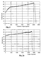
- the annealed torsion bar does not provide the precise torque-deflection curve that is desired. Characteristically, this curve (see the test data of FIG. 2) exhibits a low yield point. The real-world consequence of this low yield point is that the annealed torsion bar may yield prematurely.
- the torsion bar is again pre-stressed by twisting.
- the bar material formed into a circular bar of 9.8 mm diameter torsion bar
- overall length of 58.3 mm from tip-to-tip of the end formations
- the bar is twisted 0.5 revolution.
- the resulting test data is shown in FIG. 2a.
- the low yield point exhibited in FIG. 2 has been eliminated.
- the torque generated by the bar in its plastic regions increases somewhat linearly at about a slope of 0.0067 Nm per degree.
- Subsequent testing of this torsion bar has confirmed that the effect of removing the low yield point improves the kinematic performance in a crash.
- curve 200 of FIG. 2a which shows a dramatically reduced transition zone between elastic and plastic behavior of the torsion bar 70 and which has been achieved with pre-twisting as described above.
- the amount of pretwist will most probably vary with the diameter, length and material choice of the bar.
- FIG. 5 generally shows the construction of the major components of a torsion bar, energy absorbing seat belt retractor 20.
- the retractor 20 comprises a frame 22 with first and second sides 24a, 24b and a back 24c, each of the first and second sides includes a respective first opening 28a or 28b.
- the retractor 20 also includes a hollow spool 30 rotationally supported upon the frame.
- the spool 30 includes a center body 32 and opposing flanges 34a, 34b at respective ends of the center body.
- the center body includes a hollow bore 40 having splines 42 formed at one end thereof.
- the body also includes means such as a slot (not shown) of known construction for receiving and securing an end of a length of seat belt (seat belt webbing) 36.
- Numeral 36a designates a few layers of the seat belt 36 wound about the spool.
- a torsion bar 50 is received within the bore 40.
- the torsion bar includes a center body 52 and the end formations 52a, 52b.
- end formation 52b includes splines 56 (which drivingly engage with splines 42 of the spool).
- the notch or groove 58 (also see FIG. 4b) receives a driving key 60 of a spring arbor 62.
- the spring arbor includes a slot 64 in which is received an inner end of a rewind spring 66.
- the outer end of the rewind spring is secured to a spring cover 68.
- the cover is secured to frame side 24b and includes a circular projection 70 received within frame opening 28b.
- the circular projection serves as a bushing to rotationally support the spring arbor 62, torsion bar 50 and spool 30.
- the spool includes opposing pockets 38 located adjacent the splines 42 of the torsion bar 50. With the torsion bar in place, a tool is inserted into the pockets to locally deform the spool 30 to crimp the spool splines 42 and the torsion bar splines 56b together.
- Emergency locking retractors include a variety of ratchet or lock wheel assemblies.
- the ratchet wheel assemblies include a sensor means for causing a locking pawl to be brought into engagement with teeth on the ratchet or lock wheel to halt the protraction of the seat belt.
- Such means typically include the use of a vehicle or inertia sensor to sense vehicle deceleration above a predetermined level and a web sensor which is activated to initiate the locking of the retractor when the seat belt (webbing) is withdrawn from the spool at a rate in excess of a determinable level.
- the ratchet or lock wheel assemblies may use one or more plastic sensor pawls, which engage a plastic or metal ratchet wheel, which in turn couples a lock cup to the retractor shaft (in the present case to the torsion bar). Having coupled the lock cup to the shaft (torsion bar) the lock cup rotates. The motion of the lock cup moves a load absorbing, typically metal, locking pawl into engagement with a load absorbing metal lock wheel, thus halting, if only temporarily (when using energy absorbing components such as a torsion bar), the protraction of the seat belt.
- One such lock wheel assembly that is usable with the present invention is disclosed in US 5 529 258 or EP 0228729.
- the end formation 52a of the torsion bar 50 is secured to a ratchet wheel assembly 80.
- the assembly includes a ratchet body 82 and lock or ratchet wheel 84 having teeth 85.
- the ratchet body includes a tubular portion 86 having internal splines 88 that engage the splines 56a of the torsion bar 50.
- the lock wheel may be a part of the body 82 or a separate part that is staked thereto as illustrated.
- the ratchet body is received within frame opening 28a and is supported by a bushing 90.
- a locking pawl 92 is rotationally supported upon the frame side 24a and is movable into engagement with the teeth 85 of the lock wheel 84 in response to the activation of a vehicle or web sensor.
- the lock wheel assembly 80 includes a web sensor 220 that is coupled to sense the angular acceleration of rotation of the spool 30. As illustrated, the web sensor is coupled to the torsion bar 50 via the lock wheel assembly, the speed of which (prior to lockup) is that of the spool.
- the lock wheel assembly further includes a vehicle sensor 222. As mentioned above, the specific implementation of the web and vehicle sensors will vary, however, this is known in the art. Whenever either the vehicle or the web sensor is activated the lock pawl 92 is brought, via known mechanisms, into locking engagement with a lock wheel 84.
- the operation of the retractor 20 is generally the same of that outlined above.
- the end 52a of the torsion bar 50 is locked from further rotation and the seat belt is loaded as the vehicle occupant moves or attempts to move forward.
- the vehicle occupant load is transferred to the spool 30, via the belt 36, whose motion is opposed by the reaction torque generated as the spring end 52b of the torsion bar is rotated.
- Increased vehicle occupant load will cause the spool 30 and the torsion bar to rotate, in opposition to the reaction force, thereby protracting the seat belt 36 and permitting the vehicle occupant to move forward in a controlled manner.
- the prior art has referred to energy absorbing seat belt retractors as constant force retractors.
- This reference is presumably to a theoretical constant plastic reaction torque (or force) that is achieved when the energy absorbing device, such as the torsion bar or crush ring, is deformed into its plastic region. Having generated this constant torque at for example the torsion bar, this force is communicated to the retractor spool and then to the seat belt.
- the goal is to produce a retractor that displays a generally constant reaction force, even using a perfect torsion bar will not permit this. This can be seen by the following.
- F the reaction force measured at the belt
- D the effective diameter of the spool plus any roll of seat belt webbing thereon
- F the reaction torque generated by the torsion bar.
- the torsion bar begins to twist and generate a reaction torque.
- the effective diameter, D reduces. Consequently, even if the torque, T, is constant the belt reaction force may vary in correspondence to the belt removed from the spool.
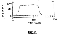
- FIG. 6 is test data for a crash simulation of using a 95th percentile hybrid III dummy and the above described torsion bar retractor.
- This test data shows that a retractor using the present invention can generate a reaction force that is remarkably constant.
- D 50 mm.
- the seat belt used was conventional woven polyester seat belt material with an elongation of about 6% and a thickness of about 1.27 mm. The resulting combination provided the near constant reaction force.
Landscapes
- Engineering & Computer Science (AREA)
- Mechanical Engineering (AREA)
- Automotive Seat Belt Assembly (AREA)
- Springs (AREA)
Applications Claiming Priority (3)
| Application Number | Priority Date | Filing Date | Title |
|---|---|---|---|
| US170409 | 1998-10-13 | ||
| US09/170,409 US6065706A (en) | 1998-04-14 | 1998-10-13 | Energy absorbing seat belt retractor having a torsion bar |
| PCT/US1999/015623 WO2000021802A1 (en) | 1998-10-13 | 1999-07-08 | Seat belt retractor having a torsion bar |
Publications (2)
| Publication Number | Publication Date |
|---|---|
| EP1119473A1 EP1119473A1 (en) | 2001-08-01 |
| EP1119473B1 true EP1119473B1 (en) | 2004-03-03 |
Family
ID=22619748
Family Applications (1)
| Application Number | Title | Priority Date | Filing Date |
|---|---|---|---|
| EP99933863A Expired - Lifetime EP1119473B1 (en) | 1998-10-13 | 1999-07-08 | Seat belt retractor having a torsion bar |
Country Status (10)
| Country | Link |
|---|---|
| US (2) | US6065706A (enExample) |
| EP (1) | EP1119473B1 (enExample) |
| JP (1) | JP4191898B2 (enExample) |
| KR (1) | KR100600250B1 (enExample) |
| AT (1) | ATE260790T1 (enExample) |
| AU (1) | AU750080B2 (enExample) |
| BR (1) | BR9912648A (enExample) |
| CA (1) | CA2338241A1 (enExample) |
| DE (1) | DE69915324T2 (enExample) |
| WO (1) | WO2000021802A1 (enExample) |
Families Citing this family (10)
| Publication number | Priority date | Publication date | Assignee | Title |
|---|---|---|---|---|
| US6158816A (en) * | 1997-11-05 | 2000-12-12 | Breed Automotive Technology, Inc. | Energy absorbing torsion bar seat belt retractor with sharp onset property |
| JP4518446B2 (ja) * | 1999-07-02 | 2010-08-04 | タカタ株式会社 | シートベルト巻取装置用トーションバーおよびこれを備えたシートベルト巻取装置 |
| DE10122910B4 (de) | 2001-05-11 | 2004-10-21 | Breed Automotive Technology, Inc., Lakeland | Rückhaltevorrichtung für einen Fahrzeuginsassen |
| US6692027B2 (en) * | 2001-10-11 | 2004-02-17 | Delphi Technologies, Inc. | Load limiting seat restraint retractor |
| AU2003250042A1 (en) * | 2002-08-03 | 2004-02-25 | Autoliv Development Ab | Belt retractor/belt tensioner combination comprising a belt shaft-integrated tensioning drive |
| DE10357979B4 (de) * | 2003-12-11 | 2006-10-05 | Sfs Intec Holding Ag | Torsionsstab zum Einsatz bei Gurtaufrollern für Sicherheitsgurte |
| ES2385367T3 (es) * | 2007-10-03 | 2012-07-23 | Key Safety Systems, Inc. | Sistema de cinturón de seguridad para adultos y niños |
| US7954854B2 (en) * | 2008-07-15 | 2011-06-07 | Autoliv Asp, Inc. | Seat belt retractor and torsion bar providing secondary load limiting |
| JP5662029B2 (ja) * | 2010-01-22 | 2015-01-28 | 日鉄住金精圧品株式会社 | トーションバー |
| US11014529B2 (en) | 2019-04-30 | 2021-05-25 | Joyson Safety Systems Acquisition Llc | Seat belt retractor |
Citations (1)
| Publication number | Priority date | Publication date | Assignee | Title |
|---|---|---|---|---|
| WO1999052746A1 (en) * | 1998-04-14 | 1999-10-21 | Breed Automotive Technology, Inc. | Seat belt retractor with torsion bar |
Family Cites Families (22)
| Publication number | Priority date | Publication date | Assignee | Title |
|---|---|---|---|---|
| FR1402106A (fr) * | 1964-04-29 | 1965-06-11 | Renault | Ressorts rectilignes de torsion et leur procédé de fabrication |
| DE2026277C3 (de) * | 1970-05-29 | 1974-07-11 | Ernst Prof. Dipl.-Ing. Dr. Techn. 3300 Braunschweig Fiala | Vorrichtung zum Aufnehmen von Energie für Rückhalteeinrichtungen für Fahrzeuginsassen, insbesondere für Sicherheitsgurte |
| DE2222742C3 (de) * | 1972-05-09 | 1974-09-26 | Klink, Wolf-Dieter, 7071 Lindach | Energiewandler für Sicherheitsgurte |
| DE2230994C2 (de) * | 1972-06-24 | 1982-08-12 | Kangol-Teka Autoteile GmbH, 6238 Hofheim | Sicherheitsgurt-Sperrvorrichtung mit Bremseinrichtung |
| US3961761A (en) * | 1974-01-21 | 1976-06-08 | Hans Kolb Kg | Storage device for a safety belt |
| JPS6111085Y2 (enExample) * | 1979-10-16 | 1986-04-08 | ||
| EP0228114A1 (en) | 1982-04-20 | 1987-07-08 | Ase (Uk) Limited | Emergency locking vehicle seat belt retractor |
| JPS59190529A (ja) * | 1983-04-13 | 1984-10-29 | Mitsubishi Steel Mfg Co Ltd | 金属製ト−シヨンバ−及びその製造方法 |
| JPS62246636A (ja) * | 1987-04-10 | 1987-10-27 | Daido Steel Co Ltd | 中空ト−シヨンバ−の製造方法 |
| JP2592171B2 (ja) * | 1990-06-11 | 1997-03-19 | リズム自動車部品製造株式会社 | ステアリング用トーションバーの成形方法 |
| DE59207382D1 (de) * | 1992-01-31 | 1996-11-21 | Trw Repa Gmbh | Gurtstraffer in einem Rückhaltesystem für Fahrzeuginsassen |
| DE4209540A1 (de) * | 1992-03-24 | 1993-09-30 | Trw Repa Gmbh | Gurtaufroller mit an der Gurtspule angreifendem Gurtstraffer |
| US5624083A (en) * | 1992-07-13 | 1997-04-29 | Trw Repa Gmbh | Belt retractor with a belt pretensioner acting on the belt drum |
| JP2618159B2 (ja) * | 1992-07-31 | 1997-06-11 | 日本発条株式会社 | 中空トーションバー |
| DE4314883A1 (de) * | 1993-05-05 | 1994-11-10 | Trw Repa Gmbh | Sicherheitsgurtaufroller |
| DE4438097A1 (de) * | 1994-10-25 | 1996-05-02 | Trw Repa Gmbh | Gurtaufroller mit integriertem Gurtstraffer und Energiewandler |
| US5529258A (en) * | 1994-12-21 | 1996-06-25 | Alliedsignal Inc. | Secondary locking mechanism for retractor with pretensioner |
| GB2314535B (en) * | 1995-04-14 | 1998-08-19 | Autoliv Dev | Belt roller with damped force limiter |
| DE29516628U1 (de) * | 1995-10-20 | 1996-01-25 | Trw Occupant Restraint Systems Gmbh, 73551 Alfdorf | Gurtaufroller mit Gurtstraffer und Kraftbegrenzung |
| KR200146520Y1 (ko) * | 1995-12-30 | 1999-06-15 | 정몽규 | 시트벨트 리트랙터 구조 |
| DE29605115U1 (de) * | 1996-03-19 | 1996-07-18 | Trw Occupant Restraint Systems Gmbh, 73551 Alfdorf | Gurtaufroller |
| DE19614730C1 (de) * | 1996-04-15 | 1997-06-19 | Daimler Benz Ag | Gurtkraftbegrenzer für einen Fahrzeugsicherheitsgurt |
-
1998
- 1998-10-13 US US09/170,409 patent/US6065706A/en not_active Expired - Lifetime
-
1999
- 1999-07-08 EP EP99933863A patent/EP1119473B1/en not_active Expired - Lifetime
- 1999-07-08 DE DE69915324T patent/DE69915324T2/de not_active Expired - Fee Related
- 1999-07-08 BR BR9912648-6A patent/BR9912648A/pt not_active IP Right Cessation
- 1999-07-08 AT AT99933863T patent/ATE260790T1/de not_active IP Right Cessation
- 1999-07-08 AU AU49824/99A patent/AU750080B2/en not_active Ceased
- 1999-07-08 KR KR1020017004516A patent/KR100600250B1/ko not_active Expired - Fee Related
- 1999-07-08 JP JP2000575731A patent/JP4191898B2/ja not_active Expired - Lifetime
- 1999-07-08 CA CA002338241A patent/CA2338241A1/en not_active Abandoned
- 1999-07-08 WO PCT/US1999/015623 patent/WO2000021802A1/en not_active Ceased
-
2000
- 2000-01-05 US US09/477,780 patent/US6186432B1/en not_active Expired - Lifetime
Patent Citations (1)
| Publication number | Priority date | Publication date | Assignee | Title |
|---|---|---|---|---|
| WO1999052746A1 (en) * | 1998-04-14 | 1999-10-21 | Breed Automotive Technology, Inc. | Seat belt retractor with torsion bar |
Also Published As
| Publication number | Publication date |
|---|---|
| AU4982499A (en) | 2000-05-01 |
| DE69915324D1 (de) | 2004-04-08 |
| CA2338241A1 (en) | 2000-04-20 |
| US6065706A (en) | 2000-05-23 |
| AU750080B2 (en) | 2002-07-11 |
| JP2002527284A (ja) | 2002-08-27 |
| BR9912648A (pt) | 2001-08-14 |
| JP4191898B2 (ja) | 2008-12-03 |
| EP1119473A1 (en) | 2001-08-01 |
| KR100600250B1 (ko) | 2006-07-13 |
| ATE260790T1 (de) | 2004-03-15 |
| DE69915324T2 (de) | 2005-03-17 |
| US6186432B1 (en) | 2001-02-13 |
| WO2000021802A1 (en) | 2000-04-20 |
| KR20010080080A (ko) | 2001-08-22 |
Similar Documents
| Publication | Publication Date | Title |
|---|---|---|
| US6739541B2 (en) | Seat belt retractor with load limiting | |
| US5899402A (en) | Torsion bar with sharp, rapid onset property and retractor | |
| US6474587B2 (en) | Seat belt retractor | |
| EP1119473B1 (en) | Seat belt retractor having a torsion bar | |
| US7954854B2 (en) | Seat belt retractor and torsion bar providing secondary load limiting | |
| JPH11510767A (ja) | プレテンショナを分離した荷重制限スプールを備えるリトラクタ | |
| JP5013458B2 (ja) | シートベルトリトラクタおよびこれを備えたシートベルト装置 | |
| EP1028784B1 (en) | Energy absorbing torsion bar seat belt retractor | |
| US7874589B2 (en) | Seat belt retractor | |
| US20020092943A1 (en) | Energy absorbing seat belt retractor | |
| MXPA01001564A (es) | Reactor de cinturon de seguridad que tiene una barra de torsion | |
| EP0928722A3 (en) | Seat belt retractor | |
| MXPA00006363A (en) | Seat belt retractor with torsion bar | |
| JPH10250529A (ja) | シートベルト用エネルギー吸収機構 | |
| JP2001310706A (ja) | シートベルト装置 | |
| DE20304993U1 (de) | Gurtaufroller für einen Fahrzeug-Sicherheitsgurt |
Legal Events
| Date | Code | Title | Description |
|---|---|---|---|
| PUAI | Public reference made under article 153(3) epc to a published international application that has entered the european phase |
Free format text: ORIGINAL CODE: 0009012 |
|
| 17P | Request for examination filed |
Effective date: 20010123 |
|
| AK | Designated contracting states |
Kind code of ref document: A1 Designated state(s): AT BE CH CY DE DK ES FI FR GB GR IE IT LI LU MC NL PT SE |
|
| 17Q | First examination report despatched |
Effective date: 20030213 |
|
| GRAP | Despatch of communication of intention to grant a patent |
Free format text: ORIGINAL CODE: EPIDOSNIGR1 |
|
| GRAS | Grant fee paid |
Free format text: ORIGINAL CODE: EPIDOSNIGR3 |
|
| GRAA | (expected) grant |
Free format text: ORIGINAL CODE: 0009210 |
|
| AK | Designated contracting states |
Kind code of ref document: B1 Designated state(s): AT BE CH CY DE DK ES FI FR GB GR IE IT LI LU MC NL PT SE |
|
| PG25 | Lapsed in a contracting state [announced via postgrant information from national office to epo] |
Ref country code: NL Free format text: LAPSE BECAUSE OF FAILURE TO SUBMIT A TRANSLATION OF THE DESCRIPTION OR TO PAY THE FEE WITHIN THE PRESCRIBED TIME-LIMIT Effective date: 20040303 Ref country code: LI Free format text: LAPSE BECAUSE OF FAILURE TO SUBMIT A TRANSLATION OF THE DESCRIPTION OR TO PAY THE FEE WITHIN THE PRESCRIBED TIME-LIMIT Effective date: 20040303 Ref country code: FI Free format text: LAPSE BECAUSE OF FAILURE TO SUBMIT A TRANSLATION OF THE DESCRIPTION OR TO PAY THE FEE WITHIN THE PRESCRIBED TIME-LIMIT Effective date: 20040303 Ref country code: CY Free format text: LAPSE BECAUSE OF FAILURE TO SUBMIT A TRANSLATION OF THE DESCRIPTION OR TO PAY THE FEE WITHIN THE PRESCRIBED TIME-LIMIT Effective date: 20040303 Ref country code: CH Free format text: LAPSE BECAUSE OF FAILURE TO SUBMIT A TRANSLATION OF THE DESCRIPTION OR TO PAY THE FEE WITHIN THE PRESCRIBED TIME-LIMIT Effective date: 20040303 Ref country code: BE Free format text: LAPSE BECAUSE OF FAILURE TO SUBMIT A TRANSLATION OF THE DESCRIPTION OR TO PAY THE FEE WITHIN THE PRESCRIBED TIME-LIMIT Effective date: 20040303 Ref country code: AT Free format text: LAPSE BECAUSE OF FAILURE TO SUBMIT A TRANSLATION OF THE DESCRIPTION OR TO PAY THE FEE WITHIN THE PRESCRIBED TIME-LIMIT Effective date: 20040303 |
|
| REG | Reference to a national code |
Ref country code: GB Ref legal event code: FG4D |
|
| REG | Reference to a national code |
Ref country code: CH Ref legal event code: EP |
|
| REG | Reference to a national code |
Ref country code: IE Ref legal event code: FG4D |
|
| REF | Corresponds to: |
Ref document number: 69915324 Country of ref document: DE Date of ref document: 20040408 Kind code of ref document: P |
|
| PG25 | Lapsed in a contracting state [announced via postgrant information from national office to epo] |
Ref country code: SE Free format text: LAPSE BECAUSE OF FAILURE TO SUBMIT A TRANSLATION OF THE DESCRIPTION OR TO PAY THE FEE WITHIN THE PRESCRIBED TIME-LIMIT Effective date: 20040603 Ref country code: GR Free format text: LAPSE BECAUSE OF FAILURE TO SUBMIT A TRANSLATION OF THE DESCRIPTION OR TO PAY THE FEE WITHIN THE PRESCRIBED TIME-LIMIT Effective date: 20040603 Ref country code: DK Free format text: LAPSE BECAUSE OF FAILURE TO SUBMIT A TRANSLATION OF THE DESCRIPTION OR TO PAY THE FEE WITHIN THE PRESCRIBED TIME-LIMIT Effective date: 20040603 |
|
| PG25 | Lapsed in a contracting state [announced via postgrant information from national office to epo] |
Ref country code: ES Free format text: LAPSE BECAUSE OF FAILURE TO SUBMIT A TRANSLATION OF THE DESCRIPTION OR TO PAY THE FEE WITHIN THE PRESCRIBED TIME-LIMIT Effective date: 20040614 |
|
| PG25 | Lapsed in a contracting state [announced via postgrant information from national office to epo] |
Ref country code: LU Free format text: LAPSE BECAUSE OF NON-PAYMENT OF DUE FEES Effective date: 20040708 Ref country code: IE Free format text: LAPSE BECAUSE OF NON-PAYMENT OF DUE FEES Effective date: 20040708 |
|
| PG25 | Lapsed in a contracting state [announced via postgrant information from national office to epo] |
Ref country code: MC Free format text: LAPSE BECAUSE OF NON-PAYMENT OF DUE FEES Effective date: 20040731 |
|
| NLV1 | Nl: lapsed or annulled due to failure to fulfill the requirements of art. 29p and 29m of the patents act | ||
| REG | Reference to a national code |
Ref country code: CH Ref legal event code: PL |
|
| ET | Fr: translation filed | ||
| PLBE | No opposition filed within time limit |
Free format text: ORIGINAL CODE: 0009261 |
|
| STAA | Information on the status of an ep patent application or granted ep patent |
Free format text: STATUS: NO OPPOSITION FILED WITHIN TIME LIMIT |
|
| 26N | No opposition filed |
Effective date: 20041206 |
|
| REG | Reference to a national code |
Ref country code: IE Ref legal event code: MM4A |
|
| REG | Reference to a national code |
Ref country code: GB Ref legal event code: 732E |
|
| REG | Reference to a national code |
Ref country code: FR Ref legal event code: TP |
|
| PG25 | Lapsed in a contracting state [announced via postgrant information from national office to epo] |
Ref country code: PT Free format text: LAPSE BECAUSE OF NON-PAYMENT OF DUE FEES Effective date: 20040803 |
|
| PGFP | Annual fee paid to national office [announced via postgrant information from national office to epo] |
Ref country code: FR Payment date: 20090708 Year of fee payment: 11 |
|
| PGFP | Annual fee paid to national office [announced via postgrant information from national office to epo] |
Ref country code: GB Payment date: 20090612 Year of fee payment: 11 Ref country code: DE Payment date: 20090730 Year of fee payment: 11 |
|
| PGFP | Annual fee paid to national office [announced via postgrant information from national office to epo] |
Ref country code: IT Payment date: 20090725 Year of fee payment: 11 |
|
| GBPC | Gb: european patent ceased through non-payment of renewal fee |
Effective date: 20100708 |
|
| REG | Reference to a national code |
Ref country code: FR Ref legal event code: ST Effective date: 20110331 |
|
| PG25 | Lapsed in a contracting state [announced via postgrant information from national office to epo] |
Ref country code: DE Free format text: LAPSE BECAUSE OF NON-PAYMENT OF DUE FEES Effective date: 20110201 |
|
| REG | Reference to a national code |
Ref country code: DE Ref legal event code: R119 Ref document number: 69915324 Country of ref document: DE Effective date: 20110201 |
|
| PG25 | Lapsed in a contracting state [announced via postgrant information from national office to epo] |
Ref country code: FR Free format text: LAPSE BECAUSE OF NON-PAYMENT OF DUE FEES Effective date: 20100802 Ref country code: IT Free format text: LAPSE BECAUSE OF NON-PAYMENT OF DUE FEES Effective date: 20100708 |
|
| PG25 | Lapsed in a contracting state [announced via postgrant information from national office to epo] |
Ref country code: GB Free format text: LAPSE BECAUSE OF NON-PAYMENT OF DUE FEES Effective date: 20100708 |