EP1118781A1 - Pleuellagerung - Google Patents
Pleuellagerung Download PDFInfo
- Publication number
- EP1118781A1 EP1118781A1 EP00127913A EP00127913A EP1118781A1 EP 1118781 A1 EP1118781 A1 EP 1118781A1 EP 00127913 A EP00127913 A EP 00127913A EP 00127913 A EP00127913 A EP 00127913A EP 1118781 A1 EP1118781 A1 EP 1118781A1
- Authority
- EP
- European Patent Office
- Prior art keywords
- connecting rod
- bearing
- axial
- rolling
- area
- Prior art date
- Legal status (The legal status is an assumption and is not a legal conclusion. Google has not performed a legal analysis and makes no representation as to the accuracy of the status listed.)
- Ceased
Links
- 238000005096 rolling process Methods 0.000 claims description 140
- 239000000314 lubricant Substances 0.000 claims description 16
- 239000000463 material Substances 0.000 claims description 13
- 230000001050 lubricating effect Effects 0.000 claims description 4
- 230000006835 compression Effects 0.000 claims description 3
- 238000007906 compression Methods 0.000 claims description 3
- 230000006698 induction Effects 0.000 claims description 3
- 239000002184 metal Substances 0.000 claims description 3
- 239000000919 ceramic Substances 0.000 claims description 2
- 239000003921 oil Substances 0.000 description 16
- 238000005461 lubrication Methods 0.000 description 14
- 238000013461 design Methods 0.000 description 7
- 230000009467 reduction Effects 0.000 description 6
- 238000003860 storage Methods 0.000 description 5
- 229910000831 Steel Inorganic materials 0.000 description 4
- 238000011161 development Methods 0.000 description 4
- 230000018109 developmental process Effects 0.000 description 4
- 238000004519 manufacturing process Methods 0.000 description 4
- 239000010959 steel Substances 0.000 description 4
- 230000007704 transition Effects 0.000 description 3
- 229910010293 ceramic material Inorganic materials 0.000 description 2
- 239000011248 coating agent Substances 0.000 description 2
- 238000000576 coating method Methods 0.000 description 2
- 230000001419 dependent effect Effects 0.000 description 2
- 238000009434 installation Methods 0.000 description 2
- 230000010354 integration Effects 0.000 description 2
- 239000010687 lubricating oil Substances 0.000 description 2
- 239000007787 solid Substances 0.000 description 2
- 230000001133 acceleration Effects 0.000 description 1
- 230000002411 adverse Effects 0.000 description 1
- 230000015572 biosynthetic process Effects 0.000 description 1
- 238000005266 casting Methods 0.000 description 1
- 238000010276 construction Methods 0.000 description 1
- 238000001816 cooling Methods 0.000 description 1
- 238000006073 displacement reaction Methods 0.000 description 1
- 238000009826 distribution Methods 0.000 description 1
- 238000005553 drilling Methods 0.000 description 1
- 230000000694 effects Effects 0.000 description 1
- 238000005516 engineering process Methods 0.000 description 1
- 239000000446 fuel Substances 0.000 description 1
- 230000012447 hatching Effects 0.000 description 1
- 238000010438 heat treatment Methods 0.000 description 1
- 238000010348 incorporation Methods 0.000 description 1
- 238000003780 insertion Methods 0.000 description 1
- 230000037431 insertion Effects 0.000 description 1
- 230000007774 longterm Effects 0.000 description 1
- 238000003754 machining Methods 0.000 description 1
- 239000003595 mist Substances 0.000 description 1
- -1 polytetrafluoroethylene Polymers 0.000 description 1
- 229920001343 polytetrafluoroethylene Polymers 0.000 description 1
- 239000004810 polytetrafluoroethylene Substances 0.000 description 1
- 238000012545 processing Methods 0.000 description 1
Images


Classifications
-
- F—MECHANICAL ENGINEERING; LIGHTING; HEATING; WEAPONS; BLASTING
- F16—ENGINEERING ELEMENTS AND UNITS; GENERAL MEASURES FOR PRODUCING AND MAINTAINING EFFECTIVE FUNCTIONING OF MACHINES OR INSTALLATIONS; THERMAL INSULATION IN GENERAL
- F16C—SHAFTS; FLEXIBLE SHAFTS; ELEMENTS OR CRANKSHAFT MECHANISMS; ROTARY BODIES OTHER THAN GEARING ELEMENTS; BEARINGS
- F16C9/00—Bearings for crankshafts or connecting-rods; Attachment of connecting-rods
- F16C9/04—Connecting-rod bearings; Attachments thereof
Definitions
- the invention relates to a connecting rod bearing for storing at least one connecting rod in the area of a crank pin of a crankshaft of a reciprocating machine according to the preamble of claim 1.
- Conrod bearings of this type include axial guide means for axially guiding the connecting rod. These axial guide means are intended to cause an axial displacement of the connecting rod limit or largely prevent the crank pin on which it is rotatably mounted.
- thrust surfaces can be treated on the one hand by smooth rolling treatment smoothed and hardened cold.
- the invention has for its object a connecting rod bearing of the generic type propose a reliable axial guidance with a minimum of friction loss enables.
- the connecting rod bearings according to the invention are characterized in that the axial guide means comprise at least one axial bearing which is essentially free of sliding friction. This is designed so that solid sliding friction in the area of the thrust bearing is reliable is avoided. This can be achieved that friction losses in the area of Axial guidance interacting elements are reduced to a minimum. According to the invention, this is possible above all in two different ways a reciprocating piston engine can alternatively or jointly be provided.
- the use of roller bearings for the axial guidance of the connecting rods can be the conventional one sliding solid friction replaced by a much lower rolling friction become.
- the axial guide means include at least one rolling bearing.
- a rolling bearing e.g. between a connecting rod and an adjacent crank arm or between two directly neighboring connecting rods are practically only generating rolling friction in this area.
- the at conventional axial guide means very narrow lubrication gap between those in operation The reciprocating machine elements rotating against each other can be enlarged become. While with conventional solutions with sliding surfaces the lubricating gap practically disappears in the area of the contact and in adjacent area is usually less than approx.
- a suitable larger value can be set, e.g. on the order of can be approximately 100 ⁇ m to approximately 200 ⁇ m.
- Lubricating oil must be pressed through a narrow lubricating gap
- the advantages come in particular Multi-cylinder reciprocating machines with a corresponding number of such lubrication points to carry. In particular, the cold start properties can also be significantly improved become.
- the rolling bearing as a pure Thrust bearing is formed. This makes the roller bearing particularly simple and inexpensive getting produced. Forces acting in the radial direction, i.e. transverse to the extension of the Crank pins can occur due to the bearing normally designed as a plain bearing of the connecting rod eye on the crank pin.
- a pure axial roller bearing also enables a connecting rod play in the radial direction that may be desired.
- the roller bearing is designed as a ball bearing. This ensures reliable, low-friction operation even at high speeds.
- the design of the roller bearing of the axial guide means as a ball bearing takes into account that the forces that usually occur in the axial direction are relatively small, so that the advantages that result from the punctiform contact between the rolling elements and the rolling surface or raceway with regard to the rolling friction may be existing disadvantages with regard to axial load capacity predominate.
- a roller bearing of a connecting rod bearing according to the invention can also be designed as a roller bearing. Since there is a line contact between the cylindrical rolling elements, for example, and the associated rolling surface, the number of rolling elements can be lower in comparison with ball bearings in such solutions, which can offer manufacturing advantages.
- all other forms of rolling elements such as barrel-shaped rollers, are alternatively possible.
- a connecting rod is a large one Conrod eye with axial end faces and that at least one of the axial End faces rolling elements of the rolling bearing are arranged, for example in a concentric arranged in an annular arrangement to the axis of rotation of the connecting rod eye.
- the Movable elements of the rolling bearing can thus be used in the production of the connecting rod this can be installed.
- the assigned rolling surface or raceway for the rolling elements can then, for example, on an axial end face of a crank arm of the crankshaft or, for arrangements with several adjacent connecting rods in the area of a crank pin, be provided on a large connecting rod eye of an adjacent connecting rod. It is in principle, however, it is also possible that the rolling elements of the rolling bearing according to the invention in reversely arranged in the region of the crank arms of the crankshaft.
- the rolling bearing one of the rolling elements assigned rolling surface or raceway for the rolling elements which by suitable Treatment is hardened.
- this can be done, for example, using laser technology
- Material structure in the area of the raceway can be hardened locally or it can be a Rolling area comprehensive induction hardening can be performed.
- one Rolling surface also on a separate bearing element made of a hardened or hard Material, e.g. made of hard metal or ceramic.
- crankshafts made in one piece from a casting or forged.
- Associated connecting rods are then known performed in the area of the large connecting rod eye, one with the connecting rod shaft connected connecting rod foot and a connecting rod cover screwed together with this form the big connecting rod eye.
- the rolling bearing has rolling elements that are directly in a connecting rod in the area of the large connecting rod eye are formed receiving opening.
- rolling elements of the rolling bearing in a separate rolling element carrier or cage and this into a correspondingly shaped receiving opening on the connecting rod head to install.
- the rolling element cage can be closed in a ring shape with undivided connecting rod eyes his.
- rolling elements directly into a form-fitting receiving opening on the front side of a connecting rod head (or a crank arm) it is advisable to Secure the rolling elements against falling out of the receiving opening after insertion.
- this can be done by caulking the edge regions the receiving opening, so that after inserting the rolling element Entrance area of the emergency opening is reduced so far that the rolling element due to the material of the connecting rod head (or crank arm) surrounding it is secured against falling out.
- the rolling bearing has rolling elements which in Axial direction are spring-loaded. This can compensate for thermal expansion effects and there can be a reliable, continuous rolling contact between rolling elements and assigned rolling surface at all operating temperatures. The precision of the axial guidance is then the same at all operating temperatures high.
- the axial spring load can be applied to individual rolling elements or groups of Rolling elements or possibly on a rolling element carrier carrying several rolling elements Act. It is also possible that one attached, for example, to a crank web Bearing element on which the rolling surface is formed is spring-loaded such that also with a slightly varying axial distance between the connecting rod and the crank arm, a permanent one Roll contact of the rolling bearing elements is ensured.
- the lubricant flow can be in the hydrodynamic range Warehouse are controlled. So it is possible that recesses at least in sections with respect to the connecting rod's axis of rotation, more or less straight in the radial direction. It is also possible that depressions run in a spiral, so that they are provided with depressions in the circumferential direction or in the circumferential direction Surface are curved.
- the depressions are expedient by a circumferential direction varying axial depth formed like a ramp, the orientation of the Ramp is expedient so that the recess in a discharge area for lubricant is deeper and flattens out towards the diversion area. From the diversion area the lubricant is pressed into the lubrication gap.
- crankshafts can have crank webs, for example, which serve as the axial limitation of crank pins, on which a preferably hardened rolling surface for rolling elements of a rolling bearing Rolling area is provided or one to form a hydrodynamic connecting rod axial bearing specially designed face. Possibly. can a crankshaft also rolling elements of the Bear rolling bearing.
- the invention also covers connecting rod axial bearings according to the invention designed reciprocating piston machines, which combine the advantages of the invention for example through lower fuel consumption and / or improvement of Show cold start properties.
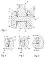
- FIG. 1 schematically shows an axial section of a crankshaft 1 of a reciprocating piston machine shown in which between two crank webs 2, 3 a substantially cylindrical Crank pin 4 is integrally formed with the crank arms.
- a connecting rod 5 On the crank pin is a connecting rod 5 with its large connecting rod eye pivoted.
- the well known Conrod eye 10 designed in a split design is essentially by a integrally formed with the connecting rod 6, approximately semicircular connecting rod 7 and a also generally semicircular connecting rod cover or bearing cap 8 is formed, the is attached to the connecting rod 7 with screws 9 (see FIG. 5).
- the big connecting rod eye 10 has an essentially circular cylindrical inner surface, which is used for receiving reasons the clarity not shown bearing shells (see. Fig. 7), with their help Radial plain bearing for rotatably supporting the connecting rod on the crank pin is formed.
- crank pin 4 goes directly into the crank webs 2, 3 at its axial ends over, as the axial limits of the space provided for the installation of the connecting rod serve on the crank pin 4.
- the crank webs face each other, at least in Area near the crank pin 4 essentially plane-parallel end faces 11, 12 primarily serve the axial guidance of the connecting rod rotatably mounted on the crank pin.
- the connecting rod has in the area of the large connecting rod eye 10 essentially plane-parallel, axial end faces 13, 14, the axial distance (measured parallel to the cylinder axis of the Crank pin 4) is a few tenths of a millimeter smaller than the axial distance between the facing one another Guide surfaces 11, 12 of the crank webs.
- a roller bearing 20, 21 is provided on each axial side of the connecting rod, which at the embodiment shown as a pure axial bearing in the form of a ball bearing and that forms part of the connecting rod bearing.
- roller bearing 21 has on the large connecting rod eye 10 in the area of the axial end face 14 of an annular arrangement of, for example eighteen rolling elements 22 in the form of steel balls.
- Each of the steel balls sits rotatably in its own receiving opening, adapted to the shape of the steel ball shape 23 directly in the steel body of the connecting rod head in the area of its axial End face 14 is provided.
- the depth of the rolling element receptacle 23 is dimensioned that an inserted rolling element with part of its circumference from the receiving opening protrudes, with typical protruding heights between the through the course of the end face 14 defined axial limitation of the connecting rod and the outstanding circumference of the rolling element can be on the order of one to two tenths of a millimeter.
- the receiving openings 23 are, for example, in the end face of the connecting rod Drilling first introduced so that the rolling element through the front opening of the Receiving opening 23 can be inserted into this.
- the rolling surface or raceway 25 assigned to the rolling elements 22 is axially opposite Area of the crankshaft end face 12 is formed. This is preferred in the annular area forming the raceway by suitable heat treatment o. The like. Locally hardened, in order to impress the punctiform roller balls to prevent in the course of operation and a permanent low-friction rolling contact between the rolling elements and the crank arms.
- the in Fig. 2nd Local hardening of the crank webs in the area of the rolling surfaces, recognizable by hatching 25 can, for example, using lasers or by induction hardening be performed. Possibly. the rolling surface 25 can still have the usual roughness smooth this area to ensure smooth rolling of the rolling element.
- a further reduction in friction can possibly be achieved by using a suitable coating of bearing treads, for example with polytetrafluoroethylene or comparable Coating materials can be achieved. Possibly. can also by use harder ceramic materials for rolling elements and / or rolling surfaces reduce friction can be achieved.
- roller bearings 20, 21 a largely play-free and low-friction axial bearing of the connecting rod between the crank arms 2, 3 can be reached.
- the rolling bodies projecting beyond the associated end faces 13, 14, that between the opposite end faces of the connecting rod and crank arm relatively wide lubrication gap 15 of a few tenths of a millimeter remains from which Oil can drain laterally faster than from conventional comparatively narrow ones Lubrication gaps with typical gap widths of a few hundredths of a millimeter.
- spherical rolling elements instead of the spherical rolling elements, largely cylindrical rolling elements are provided which are in line contact with the associated rolling surface.
- cylindrical rolling elements for example 3, 6, 9 or 12, preferably rolling cylinders distributed evenly around the circumference of the bearing, can suffice to absorb the same axial forces.
- other rolling elements are also possible, for example spherically shaped rollers.
- roller bearings 20, 21 are designed as pure axial bearings, they are due to the radial play of the connecting rod on the crank pin in its function not adversely affected. Only the im is used to absorb radial forces Example shown as a slide bearing between crank pin 4 and Connecting rod 10.
- the roller bearings 20, 21 can by the oil mist surrounding the crankshaft during operation and / or be lubricated by oil formed from those formed in the area of the crank pin Conrod radial bearing flows, which is generally provided in the crankshaft Oil channels are supplied with lubricating oil (see Fig. 7).
- Oil channels are supplied with lubricating oil (see Fig. 7).
- crank arm 31 assigned rolling surface 32 is not provided directly on the body of the crank web, but instead on a separate bearing element 33, which in a corresponding, in cross section rectangular annular groove running in the circumferential direction of the crank arm becomes.
- the bearing element 33, that for split connecting rods made of two semicircular ring segments can consist of a compared to the material of the crank web 31st harder material, for example made of hard metal or a ceramic Material.
- this embodiment differs from that described above in that each of the Rolling elements by a compression spring arranged in the rolling element receiving opening 35 36 spring-loaded in the axial direction and in the direction of the axially opposite Rolling surface 32 is biased. It can thereby be achieved that the rolling elements 34 constantly with a certain contact pressure on the opposite, assigned rolling surface 32 are pressed so that an uninterrupted contact between Rolling elements and rolling surface is ensured. Now migrates the connecting rod under operation Exploitation of its axial play slightly in the axial direction of the crank pin or not, so the compression springs 36 can ensure that the rolling elements despite varying width of the lubricating gap 37 always in contact with the opposite rolling surface stand.
- the arrangement is also in view of dimensional changes of crankshaft and / or connecting rods, which result from thermal expansion during operation can.
- the spherical rolling elements 41 are not directly in the Material of the connecting rod is inserted, but are supported by a separate rolling element carrier 42 worn in a rectangular recess 43 facing the crank pin End region of the axial end face 44 of the connecting rod head 45 is provided.
- the usage Rolling element carrier or rolling element cages 42 of this type are particularly suitable for so-called built crankshafts, such as those used in larger reciprocating machines can be used for ships. In such cases, a circumferentially closed, ring-shaped roller bearing cage inserted into an end face of a connecting rod be pushed onto the associated crank pin in the axial direction becomes.
- a rolling element cage or rolling element carrier does not necessarily have to be ring-shaped be closed, but it can also be formed in a circular segment.
- a bearing of the type recognizable in FIG. 5 can also be created by that two semicircular rolling element cages are used and in a suitable manner on Connecting rod foot or on the connecting rod cover are attached to an overall annular distribution of rolling elements to form.
- FIG. 6 shows such a long crank pin arranged between two crank webs 50, 51 53, on which two independently rotating connecting rods 53, 54 are mounted.
- a crank bearing is provided on the crank arm, in the manner of the roller bearings described so far (According to FIGS. 1 to 5) can be formed.
- the one shown on the right Connecting rod 54 similar to the connecting rod 5 shown in Fig. 1 rolling elements on both axial end faces 55, 56 have.
- the rolling elements 57 of the bearing are in the region of the End face 56 of the connecting rod 54 arranged in a ring.
- the associated rolling surface 58 is located itself on the axially opposite end face 59 of the other connecting rod 53 formed by the flat surface of an annular hardened plate 60 which is in shape and material may be substantially identical to the bearing element 33 shown in FIG. 3 can.
- a rolling surface 58 of a rolling bearing is not assigned to a cure cheek, but to a connecting rod.
- connecting rods 53, 54 can have any number of connecting rods on a common one Crank pins are axially guided in the manner according to the invention.
- FIGS. 7 to 9 advantageous embodiments according to the invention are made hydrodynamic axial bearing described for the axial guidance of a connecting rod.
- Fig. 7 shows for this purpose an axial section of a crankshaft with a on a crank pin 71 Crankshaft pivotable connecting rod 72.
- the connecting rod has the large shown Connecting rod head essentially flat, mutually parallel axial end faces 73, 74 and carries a connecting rod bearing shell inside.
- the crankshaft has the crank pin in the area of the 71 axially delimiting crank webs 76, 77, on their side facing the crank pin End faces 78, 79 and in the transition area between crank pin and crank arm Undercuts 80.
- the undercuts 80 are raidally close to the outside in the end faces 78, 79 recesses 81 machined by the material removal, which are at the embodiment shown spirally with respect to the central axis 82 of the crank pin extend radially outward (cf. right upper segment of circle in FIG. 8).
- the depressions are ramp-like in the circumferential direction of the crank web or connecting rod trained, so have a more or less continuously varying in the circumferential direction axial depth, based on the direction of rotation 83 (Fig. 8 and 9) in the inlet side Section are deeper than in the outlet section.
- the depressions can be typical have and form maximum axial depths of the order of a few tenths of a millimeter Interruptions in the otherwise flat end faces 79.
- the described type of a hydrodynamic bearing or centering 70 of the connecting rod 72 on the crank pin 71 can work as follows.
- the crankshaft rotates the crankshaft longitudinal axis is lubricated oil from the area of the main bearing 84 a diagonal bore 85 in the region of the crank pin 71 is assisted by centrifugal force.
- the oil then enters the between the substantially cylindrical inside of the Bearing shell 75 and the outside of the crank pin formed radial plain bearings for the Connecting rod 72 and flows from there axially on both sides to the axial end faces 73, 74 of the Connecting rods. With the aid of centrifugal force, the oil passes through the punctures 80 into the depressions 81.
- the lubricant experiences on the one hand due to centrifugal forces radial acceleration to the outside and secondly due to the rotating Relative movement between crank arm and connecting rod is a movement component in Circumferential direction. This causes due to the ramp-like design of the wells (Fig. 9) the lubricant in the axial gap area 86 between the crank cheek end and conrod end face is squeezed and there an axially stable Lubricant film builds up, which is a contact between the connecting rod 72 and the crank arms 76, 77 reliably prevented.
- FIG. 8 shows some advantageous, alternative shapes for the depressions, which can be incorporated both in the axial end faces of crank webs and in the axial end faces of connecting rods.
- the depressions can also run in a beam shape with respect to the axis of rotation 82.
- Radial depressions 87 of this type, which are not curved in the circumferential direction, are shown in the lower right circular segment of FIG. 8. It is also possible that a depression is not continuous in the radial direction.
- FIG. 8 shows recesses 88 curved in the shape of a segment of a circle, which extend over a certain circumferential length of, for example, one fifth to one tenth of the circumference of the end face and which, as shown in FIG. 9, flatten in a ramp-like manner in the circumferential direction.
- radial channels 89 lead into the depression from the inside of the end face facing the crank pin. These serve a particularly targeted oil supply to the deepest point of the depression.
- the reduction in cross-section of the pockets can be linear, as shown in FIG. 9, but it is alternatively also possible to make the reduction in cross-section discontinuously, for example by the base cross-section of the pocket being curved or arched.
- a reduction in cross section in the radial direction is also possible.
- crank cheek end face and / or the connecting rod end face By machining the crank cheek end face and / or the connecting rod end face to form such a deepening or equivalent deepening their function itself in a very simple and inexpensive way without the need to move it
- Axial guide means that work reliably in the manner of hydrodynamic bearings or Realize axial centering means for connecting rods on crank pins.
Landscapes
- Engineering & Computer Science (AREA)
- General Engineering & Computer Science (AREA)
- Mechanical Engineering (AREA)
- Shafts, Cranks, Connecting Bars, And Related Bearings (AREA)
Abstract
Description
Dabei sind neben Kugeln und zylindrischen Rollen alternativ auch sämtliche andere Formen von Wälzkörpern, wie z.B. tonnenförmige Rollen möglich.
- Fig. 1
- eine Ausführungsform einer Pleuellagerung eines im Längsschnitt gezeigten Pleuels auf einem Hubzapfen einer Kurbelwelle einer Hubkolbenmaschine mit Axial-Kugellagern zur axialen Führung des Pleuels an den Kurbelwangen der Kurbelwelle;
- Fig. 2
- eine Detailansicht des in Fig. 1 eingekreisten Bereichs II zur Erläuterung des Aufbaus des Axial-Kugellagers;
- Fig. 3
- eine der Fig. 2 entsprechende Detailansicht einer anderen Ausführungsform eines Axial-Kugellagers;
- Fig. 4
- einen Wälzlagerbereich einer anderen Ausführungsform, bei der ein Wälzlagerkäfig in einen hubzapfennahen Einstich am das große Pleuelauge aufnehmenden Pleuelteil des Pleuels eingesetzt ist;
- Fig. 5
- eine Perspektivansicht einer axiale Stirnseite des Pleuelteils eines zur Bildung einer erfindungsgemäßen Pleuellagerung ausgestalteten Pleuels mit im Pleuel integrierten Wälzkugeln,
- Fig. 6
- eine Pleuellagerung zweier unmittelbar benachbarter Pleuel auf einem gemeinsamen Hubzapfen einer Kurbelwelle einer Hubkolbenmaschine,
- Fig. 7
- eine Ausführungsform einer hydrodynamischen Pleuel-Axiallagerung eines im Längsschnitt gezeigten Pleuels auf einem Hubzapfen einer Kurbelwelle einer Hubkolbenmaschine, wobei die dem Hubzapfen zugewandten axialen Stirnseiten der Kurbelwangen zur Erzeugung einer hydrodynamischen Lagerung mit Vertiefungen versehen sind,
- Fig. 8
- eine schematische Darstellung einer axialen Ansicht der Stirnseite eines Pleuels oder einer Kurbelwellenwange zur Erläuterung unterschiedlicher Formen von Schmierstofführungstaschen und
- Fig. 9
- einen in Umfangsrichtung einer axialen Stirnseite verlaufenden Schnitt durch eine Schmierstoffführungsvertiefung zur Erläuterung der rampenartigen Struktur der Vertiefung.
Alternativ sind auch andere Wälzkörper möglich, z.B. ballig ausgebildete Rollen.
Dabei kann die Querschnittsverringerung der Taschen wie in Figur 9 dargestellt linear erfolgen, es ist alternativ jedoch auch möglich, die Querschnittsverringerung diskontinuierlich auszubilden, z.B. indem der Taschengrundquerschnitt gekrümmt oder bogenförmig ausgebildet ist. Zudem ist neben einer Querschnittsverringerung der Taschen in Umfangsrichtung auch eine Querschnittsverringerung in radialer Richtung möglich.
Claims (22)
- Pleuellagerung zur Lagerung mindestens eines Pleuels auf einem Hubzapfen einer Kurbelwelle einer Hubkolbenmaschine, wobei die Pleuellagerung Axialführungsmittel zur axialen Führung des Pleuels auf der Kurbelwelle aufweist, dadurch gekennzeichnet, daß die Axialführungsmittel mindestens ein im wesentlichen gleitreibungsfreies Axiallager (20, 21; 30; 40; 56; 70) aufweisen.
- Pleuellagerung nach Anspruch 1, dadurch gekennzeichnet, daß die Axialführungsmittel als gleitreibungsfreies Axiallager mindestens ein Wälzlager (20, 21; 30; 40; 56) aufweisen.
- Pleuellagerung nach Anspruch 1 oder 2, dadurch gekennzeichnet, daß im Bereich des Axiallagers zwischen axial benachbarten, gegeneinander verdrehbaren Elementen ein Schmierspalt (15) mit einer mittleren Breite von mehr als ca. 50 µm, insbesondere mit einer Breite zwischen ca. 100 µm und ca.200 µm gebildet ist.
- Pleuellagerung nach Anspruch 2 oder 3, dadurch gekennzeichnet, daß das Wälzlager (20, 21; 30; 40; 56) als reines Axialwälzlager ausgebildet ist.
- Pleuellagerung nach einem der vorhergehenden Ansprüche, dadurch gekennzeichnet, daß das Axiallager als ein Kugellager (20, 21; 30; 40; 56) oder ein Rollenlager ausgebildet ist.
- Pleuellagerung nach einem der vorhergehenden Ansprüche, dadurch gekennzeichnet, daß ein Pleuel (5; 53, 54) ein großes Pleuelauge (10) mit axialen Stirnflächen (13, 14; 44; 55, 56, 59) aufweist und daß im Bereich des großen Pleuelauges mindestens einer der axialen Stirnflächen Wälzkörper (22; 34; 41; 57) eines Wälzlagers angeordnet sind, vorzugsweise in einer ringförmigen Anordnung.
- Pleuellagerung nach einem der vorhergehenden Ansprüche, dadurch gekennzeichnet, daß das Axiallager eine zum Zusammenwirken mit Wälzkörpern eines Wälzlagers vorgesehene, vorzugsweise im wesentlichen ebene Abrollfläche (25; 32; 58) aufweist, die an einer axialen Stirnseite einer Kurbelwange (2, 3; 31; 50, 51) der Kurbelwelle oder an einem axial benachbarten Pleuel (53) vorgesehen ist.
- Pleuellagerung nach Anspruch 7, dadurch gekennzeichnet, daß die Kurbelwange (3) und/oder das Pleuel im Bereich der Abrollfläche (25) lokal gehärtet, insbesondere induktionsgehärtet oder mittels Laser gehärtet ist.
- Pleuellagerung nach Anspruch 7, dadurch gekennzeichnet, daß die Kurbelwange (31) und/oder das Pleuel (53) zur Bildung der Abrollfläche (32; 58) ein gesondertes Lagerelement (33; 60) aufweist, das aus einem harten oder gehärteten Werkstoff besteht, insbesondere aus Hartmetall oder Keramik, und an dem die Abrollfläche ausgebildet ist.
- Pleuellagerung nach einem der Ansprüche 2 bis 7, dadurch gekennzeichnet, daß das Wälzlager Wälzkörper (22; 34; 57) aufweist, die direkt in einer im Bereich einer axialen Stirnfläche eines Pleuelauges oder einer Kurbelwellenwange vorgesehene Aufnahmeöffnung (23; 35) angeordnet sind.
- Pleuellagerung nach einem der Ansprüche 2 bis 10, dadurch gekennzeichnet, daß das Wälzlager (30) in Axialrichtung federbelastet ist, wobei das Wälzlager vorzugsweise Wälzkörper (34) aufweist, die, insbesondere mittels einer zugeordneten Druckfeder (36), federbelastet sind.
- Pleuellagerung nach einem der vorhergehenden Ansprüche, dadurch gekennzeichnet, daß die Axialführungsmittel als gleitreibungsfreies Axiallager mindestens ein hydrodynamisches Lager (70) aufweisen.
- Pleuellagerung nach Anspruch 12, dadurch gekennzeichnet, daß mindestens eine axiale Stirnfläche eines Pleuels und/oder mindestens eine axiale Stirnfläche (79) einer Kurbelwange (76, 77) zur Bildung eines hydrodynamischen Axiallagers (70) durch Strukturierung der Stirnseite angepaßt ist, wobei vorzugsweise eine Stirnfläche eine oder mehrere Vertiefungen (81; 87; 88) zur Aufnahme und/oder Leitung von Schmierstoff aufweist.
- Pleuellagerung nach Anspruch 13, dadurch gekennzeichnet, daß die Vertiefungen (87) bezogen auf die Drehachse (82) des Pleuels mindestens abschnittsweise strahlförmig verlaufen.
- Pleuellagerung nach Anspruch 13 oder 14, dadurch gekennzeichnet, daß die Vertiefungen (81) bezogen auf die Drehachse des Pleuels derart spriralförmig verlaufen, daß sie in Umfangsrichtung der mit Vertiefungen versehenen Stirnfläche (79) gekrümmt sind.
- Pleuellagerung nach einem der Ansprüche 13 bis 15, dadurch gekennzeichnet, daß die Vertiefungen (81; 87, 88) durch eine in Umfangsrichtung variierende axiale Tiefe nach Art einer Rampe ausgebildet sind, wobei die Rampe vorzugsweise derart ausgerichtet ist, daß die Vertiefung in einem Einleitungsbereich für Schmierstoff tiefer ist und sich zum einem Ausleitungsbereich hin verflacht.
- Hubkolbenmaschine mit einer mindestens einen Hubzapfen (4; 52; 71) aufweisenden Kurbelwelle und mindestens einem an dem Hubzapfen mittels einer Pleuellagerung gelagerten Pleuel (5; 53, 54; 72), wobei die Pleuellagerung Axialführungsmittel zur axialen Führung des Pleuels an der Kurbelwelle aufweist, dadurch gekennzeichnet, daß die Axialführungsmittel mindestens ein im wesentlichen gleitreibungsfreies Axiallager (20, 21; 30; 40; 56; 70) aufweisen.
- Hubkolbenmaschine nach Anspruch 17, dadurch gekennzeichnet, daß das Axiallager gemäß den Merkmalen des kennzeichnenden Teils von mindestens einem der Ansprüche 2 bis 14 ausgebildet ist.
- Pleuel für eine Hubkolbenmaschine, bei dem das Pleuel im Bereich eines großen Pleuelauges (10) axiale Stirnflächen (13, 14; 44; 55, 56, 59) aufweist, dadurch gekennzeichnet, daß das Pleuel im Bereich mindestens einer seiner axialen Stirnflächen ein im wesentlichen gleitreibungsfreies Axiallager zur axialen Führung des Pleuels aufnimmt.
- Pleuel nach Anspruch 19, dadurch gekennzeichnet, daß im Bereich mindestens einer der axialen Stirnflächen im Bereich des großen Pleuelauges, vorzugsweise in einer ringförmigen Anordnung, Wälzkörper (22; 34; 41; 57) eines Wälzlagers angeordnet sind und/oder daß im Bereich mindestens einer dieser axialen Stirnflächen eine vorzugsweise ringförmige Abrollfläche (58) für Wälzkörper eines Wälzlagers angeordnet ist und/oder daß im Bereich mindestens einer dieser axialen, vorzugsweise ebenen Stirnflächen Vertiefungen (81; 87, 88) eines hydrodynamischen Axiallagers vorgesehen sind.
- Kurbelwelle mit mindestens einem Hubzapfen zum Tragen mindestens eines Pleuels und mit den Hubzapfen axial begrenzenden Kurbelwangen, die den Hubzapfen zugewandte axiale Stirnseiten aufweisen, dadurch gekennzeichnet, daß mindestens eine Stirnseite (78, 79) zur Bildung eines im wesentlichen gleitreibungsfreien Axiallagers zur axialen Führung des Pleuels ausgebildet ist.
- Kurbelwelle nach Anspruch 21, dadurch gekennzeichnet, daß im Bereich mindestens einer der axialen Stirnflächen Wälzkörper eines Wälzlagers angeordnet sind, vorzugsweise in einer ringförmigen Anordnung, und/oder daß im Bereich mindestens einer der axialen Stirnflächen eine vorzugsweise ringförmige Abrollfläche (25; 32) für Wälzkörper eines Wälzlagers angeordnet ist und/oder daß im Bereich mindestens einer der axialen, vorzugsweise ebenen Stirnflächen (78, 79) Vertiefungen (81; 87, 88) eines hydrodynamischen Axiallagers vorgesehen sind.
Applications Claiming Priority (2)
| Application Number | Priority Date | Filing Date | Title |
|---|---|---|---|
| DE2000101993 DE10001993A1 (de) | 2000-01-19 | 2000-01-19 | Pleuellagerung |
| DE10001993 | 2000-01-19 |
Publications (1)
| Publication Number | Publication Date |
|---|---|
| EP1118781A1 true EP1118781A1 (de) | 2001-07-25 |
Family
ID=7627931
Family Applications (1)
| Application Number | Title | Priority Date | Filing Date |
|---|---|---|---|
| EP00127913A Ceased EP1118781A1 (de) | 2000-01-19 | 2000-12-20 | Pleuellagerung |
Country Status (2)
| Country | Link |
|---|---|
| EP (1) | EP1118781A1 (de) |
| DE (1) | DE10001993A1 (de) |
Families Citing this family (3)
| Publication number | Priority date | Publication date | Assignee | Title |
|---|---|---|---|---|
| DE102007045543A1 (de) * | 2007-09-24 | 2008-11-20 | Audi Ag | Brennkraftmaschine, Pleuel sowie Verfahren zur Herstellung eines Pleuels |
| DE102010014769A1 (de) | 2010-04-13 | 2011-10-13 | Schaeffler Technologies Gmbh & Co. Kg | Pleuellagerung mit einem Wälzlager |
| DE102014004763A1 (de) * | 2014-04-01 | 2015-10-01 | GM Global Technology Operations LLC (n. d. Ges. d. Staates Delaware) | Wälzgelagerter Kurbeltrieb |
Citations (5)
| Publication number | Priority date | Publication date | Assignee | Title |
|---|---|---|---|---|
| FR620992A (fr) * | 1925-12-30 | 1927-05-03 | Emile Salmson Fils De | Butées placées entre l'arbre vilebrequin et le carter d'un moteur à combustion interne à cylindres rayonnants |
| FR620991A (fr) * | 1925-12-30 | 1927-05-03 | Emile Salmson Fils De | Disposition de butées placées entre la bielle maîtresse et les bras de manivelle d'un moteur étoilé à combustion interne |
| US3087342A (en) * | 1960-04-04 | 1963-04-30 | Alfred M Caddell | Piston-crank connector assembly for two-cycle engines |
| US3144786A (en) * | 1962-03-21 | 1964-08-18 | Robert A Dale | Anti-friction type mounting means for connecting rods |
| US4771744A (en) * | 1987-09-30 | 1988-09-20 | Brunswick Corporation | Connecting rod with hydrodynamic bearing |
Family Cites Families (3)
| Publication number | Priority date | Publication date | Assignee | Title |
|---|---|---|---|---|
| DE372338C (de) * | 1923-03-26 | Hermann Diehl | Kurbelzapfenlagerung fuer Kolbenkraftmaschinen | |
| US4913033A (en) * | 1986-10-07 | 1990-04-03 | Martin Bernas | Steam engine |
| DE4015536C1 (de) * | 1990-05-15 | 1991-10-10 | Audi Ag, 8070 Ingolstadt, De |
-
2000
- 2000-01-19 DE DE2000101993 patent/DE10001993A1/de not_active Withdrawn
- 2000-12-20 EP EP00127913A patent/EP1118781A1/de not_active Ceased
Patent Citations (5)
| Publication number | Priority date | Publication date | Assignee | Title |
|---|---|---|---|---|
| FR620992A (fr) * | 1925-12-30 | 1927-05-03 | Emile Salmson Fils De | Butées placées entre l'arbre vilebrequin et le carter d'un moteur à combustion interne à cylindres rayonnants |
| FR620991A (fr) * | 1925-12-30 | 1927-05-03 | Emile Salmson Fils De | Disposition de butées placées entre la bielle maîtresse et les bras de manivelle d'un moteur étoilé à combustion interne |
| US3087342A (en) * | 1960-04-04 | 1963-04-30 | Alfred M Caddell | Piston-crank connector assembly for two-cycle engines |
| US3144786A (en) * | 1962-03-21 | 1964-08-18 | Robert A Dale | Anti-friction type mounting means for connecting rods |
| US4771744A (en) * | 1987-09-30 | 1988-09-20 | Brunswick Corporation | Connecting rod with hydrodynamic bearing |
Also Published As
| Publication number | Publication date |
|---|---|
| DE10001993A1 (de) | 2001-07-26 |
Similar Documents
| Publication | Publication Date | Title |
|---|---|---|
| DE10165027C5 (de) | Wälzlager und Spindelvorrichtung für Werkzeugmaschine | |
| DE4311194C2 (de) | Gleit-/Wälzlager | |
| DE60007190T2 (de) | Elektrisch angetriebene Lenkeinrichtung | |
| DE102007061589B4 (de) | Kugellager und Halterungskonstruktion | |
| DE69627937T2 (de) | Rolle mit käfig und verfahren zur herstellung | |
| DE19750345C2 (de) | Rollenlager | |
| DE2149515B2 (de) | Schmiervorrichtung an einem Kegelrollenlager | |
| DE3308735A1 (de) | Kreuzwalzenlager | |
| EP3284966A1 (de) | Lageranordnung, insbesondere für eine strömungsmaschine, und strömungsmaschine mit einer derartigen lageranordnung | |
| EP0926368B1 (de) | Kugellager für hohe Drehzahlen | |
| DE903054C (de) | Mehrgleitflaechenlager | |
| EP2815139A1 (de) | Radiallager | |
| DE102004006313A1 (de) | Zylinderrollenlager | |
| DE4436478A1 (de) | Selbstausrichtendes Rollenlager mit Käfig | |
| EP0399297B1 (de) | Zweireihiges Pendelrollenlager | |
| EP2724039B1 (de) | Wälzlagerkäfig | |
| DE2555923B2 (de) | Wälzlagerlaufring | |
| WO2013143695A1 (de) | Feststoffgeschmiertes wälzlager | |
| DE3607729C3 (de) | Wälzlagerung, für Arbeitswalzen in Hochgeschwindigkeitswalzwerken | |
| DE4214936A1 (de) | Zapfentyp-spurwaelzlager | |
| WO2017028861A1 (de) | Schrägkugellager | |
| DE102016211906A1 (de) | Käfig für Kurbelwellenlagerung | |
| DE2831148A1 (de) | Verfahren zur herstellung einer massiven aussenhuelse fuer eine kugelbuechse | |
| DE10327641B4 (de) | Segmentlager zur radialen und axialen Lagerung eines Schlittenteils an einem Führungsteil | |
| DE102012016983B4 (de) | Wälzlager mit Wälzlagerkäfig |
Legal Events
| Date | Code | Title | Description |
|---|---|---|---|
| PUAI | Public reference made under article 153(3) epc to a published international application that has entered the european phase |
Free format text: ORIGINAL CODE: 0009012 |
|
| AK | Designated contracting states |
Kind code of ref document: A1 Designated state(s): AT BE CH CY DE DK ES FI FR GB GR IE IT LI LU MC NL PT SE TR |
|
| AX | Request for extension of the european patent |
Free format text: AL;LT;LV;MK;RO;SI |
|
| 17P | Request for examination filed |
Effective date: 20020125 |
|
| AKX | Designation fees paid |
Free format text: AT BE CH CY DE DK ES FI FR GB GR IE IT LI LU MC NL PT SE TR |
|
| 17Q | First examination report despatched |
Effective date: 20040122 |
|
| STAA | Information on the status of an ep patent application or granted ep patent |
Free format text: STATUS: THE APPLICATION HAS BEEN REFUSED |
|
| 18R | Application refused |
Effective date: 20040430 |