EP1118779A2 - Geteilte Lageranordnung - Google Patents
Geteilte Lageranordnung Download PDFInfo
- Publication number
- EP1118779A2 EP1118779A2 EP00126372A EP00126372A EP1118779A2 EP 1118779 A2 EP1118779 A2 EP 1118779A2 EP 00126372 A EP00126372 A EP 00126372A EP 00126372 A EP00126372 A EP 00126372A EP 1118779 A2 EP1118779 A2 EP 1118779A2
- Authority
- EP
- European Patent Office
- Prior art keywords
- bearing
- arrangement according
- bearing arrangement
- light metal
- preform
- Prior art date
- Legal status (The legal status is an assumption and is not a legal conclusion. Google has not performed a legal analysis and makes no representation as to the accuracy of the status listed.)
- Ceased
Links
- 229910052751 metal Inorganic materials 0.000 claims abstract description 21
- 239000002184 metal Substances 0.000 claims abstract description 21
- 239000012779 reinforcing material Substances 0.000 claims abstract description 6
- 239000000463 material Substances 0.000 claims description 9
- 239000000919 ceramic Substances 0.000 claims description 6
- 150000004767 nitrides Chemical class 0.000 claims description 6
- 229910052574 oxide ceramic Inorganic materials 0.000 claims description 6
- 239000011224 oxide ceramic Substances 0.000 claims description 6
- 230000002787 reinforcement Effects 0.000 claims description 6
- 239000000835 fiber Substances 0.000 claims description 5
- XUIMIQQOPSSXEZ-UHFFFAOYSA-N Silicon Chemical compound [Si] XUIMIQQOPSSXEZ-UHFFFAOYSA-N 0.000 claims description 4
- 238000002485 combustion reaction Methods 0.000 claims description 4
- 239000002245 particle Substances 0.000 claims description 4
- 229910052710 silicon Inorganic materials 0.000 claims description 4
- 239000010703 silicon Substances 0.000 claims description 4
- 238000005266 casting Methods 0.000 claims description 3
- 239000013078 crystal Substances 0.000 claims description 3
- 238000004663 powder metallurgy Methods 0.000 claims description 3
- 230000029142 excretion Effects 0.000 claims description 2
- CWYNVVGOOAEACU-UHFFFAOYSA-N Fe2+ Chemical compound [Fe+2] CWYNVVGOOAEACU-UHFFFAOYSA-N 0.000 abstract description 2
- 238000003754 machining Methods 0.000 description 4
- 238000004519 manufacturing process Methods 0.000 description 3
- XEEYBQQBJWHFJM-UHFFFAOYSA-N Iron Chemical compound [Fe] XEEYBQQBJWHFJM-UHFFFAOYSA-N 0.000 description 2
- 238000010276 construction Methods 0.000 description 2
- 238000004512 die casting Methods 0.000 description 2
- 230000003628 erosive effect Effects 0.000 description 2
- 238000000034 method Methods 0.000 description 2
- FYYHWMGAXLPEAU-UHFFFAOYSA-N Magnesium Chemical compound [Mg] FYYHWMGAXLPEAU-UHFFFAOYSA-N 0.000 description 1
- 229910000831 Steel Inorganic materials 0.000 description 1
- 239000000956 alloy Substances 0.000 description 1
- 229910045601 alloy Inorganic materials 0.000 description 1
- 229910052782 aluminium Inorganic materials 0.000 description 1
- XAGFODPZIPBFFR-UHFFFAOYSA-N aluminium Chemical compound [Al] XAGFODPZIPBFFR-UHFFFAOYSA-N 0.000 description 1
- 229910010293 ceramic material Inorganic materials 0.000 description 1
- 239000002131 composite material Substances 0.000 description 1
- 238000005520 cutting process Methods 0.000 description 1
- 238000007373 indentation Methods 0.000 description 1
- 230000008595 infiltration Effects 0.000 description 1
- 238000001764 infiltration Methods 0.000 description 1
- 229910052742 iron Inorganic materials 0.000 description 1
- 229910052749 magnesium Inorganic materials 0.000 description 1
- 239000011777 magnesium Substances 0.000 description 1
- 239000000155 melt Substances 0.000 description 1
- 238000002844 melting Methods 0.000 description 1
- 230000008018 melting Effects 0.000 description 1
- 239000007769 metal material Substances 0.000 description 1
- 239000000843 powder Substances 0.000 description 1
- 238000003825 pressing Methods 0.000 description 1
- 239000011856 silicon-based particle Substances 0.000 description 1
- 239000007779 soft material Substances 0.000 description 1
- 239000010959 steel Substances 0.000 description 1
- 238000003860 storage Methods 0.000 description 1
Images
Classifications
-
- F—MECHANICAL ENGINEERING; LIGHTING; HEATING; WEAPONS; BLASTING
- F16—ENGINEERING ELEMENTS AND UNITS; GENERAL MEASURES FOR PRODUCING AND MAINTAINING EFFECTIVE FUNCTIONING OF MACHINES OR INSTALLATIONS; THERMAL INSULATION IN GENERAL
- F16C—SHAFTS; FLEXIBLE SHAFTS; ELEMENTS OR CRANKSHAFT MECHANISMS; ROTARY BODIES OTHER THAN GEARING ELEMENTS; BEARINGS
- F16C9/00—Bearings for crankshafts or connecting-rods; Attachment of connecting-rods
- F16C9/02—Crankshaft bearings
Definitions
- the invention relates to a device in the preamble of claim 1 Art.
- Such a bearing arrangement is, for example, from the German one Laid-open publication 198 19 081, the bearing cover made of a hard Iron material and the storage chair, as well as the machine housing, from one softer light metal material is built.
- the cutting-like profiles on the The clamping surface of the bearing cover is machined or produced by eroding. These are preferred cutting-like profiles parallel to the central axis of the bearing on at least one Clamping surface created by machining.
- the invention has for its object a machine housing with a divided Show bearing arrangement that is light and at the same time cross loads records.
- the object is achieved by the features of claim 1.
- the invention realizes a consistent lightweight construction of the bearing arrangement, which contributes to reducing the overall weight of the internal combustion engine. Due to the reinforcement in the most mechanically stressed areas of the bearing cover, is the maximum strength despite the use of light metal and thus minimal deformation of the bearing cover with small cross sections reached.
- a preferred application of the invention is the execution of Plain bearings in internal combustion engines, especially with cylinders in a V arrangement.
- the bearing cap made of a light metal such as aluminum or magnesium by adding reinforcing materials such as oxide ceramic, nitride ceramic or carbide particles - carbide reinforcement by SiC or B 4 C - or oxide ceramic, nitride ceramic or carbide short fibers to the light metal melt, or powder for sintered bearing caps .
- At least the areas of the clamping surfaces and the screw holes are reinforced with a reinforcing material. This ensures that the cutting-like profiles on the clamping surfaces of the bearing cover are pressed into the soft clamping surfaces of the bearing bracket when the machine housing is first installed to form a positive connection.
- the bearing cap is not deformed by the screw pressure forces when it is screwed to the bearing bracket.
- the introduced particles or short fibers have the highest strength or material hardness in connection with the light metal with a low specific density.
- the thermal expansion coefficient of the composite which is similar to steel, is advantageous, since temperature-related warpage and thus the operating bearing play is minimized.
- Preform is a basic framework or core made of, for example, ceramic material, which infiltrates / impregnates with light metal and for highly stressed components such as for example bearing cover is used.
- the plain bearing bore area is excluded from the hard preform. This facilitates later stock processing, since only soft light metal is machined. This unreinforced bearing bore can be used as Warehouse functional area can be used.
- Another embodiment is the material reinforcement by the excretion of silicon crystals from the primary phase of the light metal melt. That means, that the high silicon content (greater than 16% by volume) in the light metal, a hypereutectic alloy, when the light metal solidifies from the melt, in Form of silicon crystals is excreted. The addition of hard materials in the light metal melt is therefore eliminated.
- the bearing cover can also can be produced by powder metallurgy with a high proportion of silicon particles.
- Another advantage of the above-mentioned manufacturing processes is that cutting-like profiles with a casting process such as the die casting process Infiltration of preforms in a vacuum, or without powder metallurgy, that is, can be generated without machining.
- bearing cover preforms By combining several bearing cover preforms, these are created using one Casting process, castable to a bedplate.
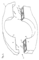
- the attached drawing shows a preferred embodiment of the Invention.
- a split bearing arrangement 1 in a machine housing 2 for one Crankshaft plain bearing 3 in an internal combustion engine, not shown, consists of a bearing chair 4 and a bearing cover 5.
- the bearing chair 4 and the bearing cover 5 have corresponding clamping surfaces 6 and 6 '.
- the clamping surfaces 6 of the Bearing cover 5 have a cutting-like profile 7, which is parallel to Bearing center axis runs.
- the corresponding clamping surfaces of the bearing chair 4 are plan.
- Bores 8 are in the bearing cover 5; 8 'for screwing Bearing cover 5 with bearing chair 4 is provided.
- the bearing cap material of the bearing cap 5 harder than execute the rest of the bearing assembly 1. Through this measure, the Pressing the bearing cover 5 into the bearing block 4 ensured.
- the Bearing cover reinforcement is achieved by adding oxide ceramic, nitride ceramic or carbide particles or oxide ceramic, nitride ceramic or carbide short fibers for light metal melting.
Landscapes
- Engineering & Computer Science (AREA)
- General Engineering & Computer Science (AREA)
- Mechanical Engineering (AREA)
- Shafts, Cranks, Connecting Bars, And Related Bearings (AREA)
- Mounting Of Bearings Or Others (AREA)
Abstract
Description
- ganz eingegossen, das heisst, die Gleitlageroberfläche ist im Bearbeitungsbereich des Gleitlagers aus Leichtmetall;
- im Bereich der Gleitlageroberfläche nicht von Leichtmetall bedeckt, dafür ist ein weicher Werkstoff auf die Preform aufbringbar, der wiederum als Gleitlagermaterial einsetzbar ist;
- zur Erleichterung der Bearbeitbarkeit gegebenenfalls im Bohrungsbereich der Schrauben unverstärkt.
- 1
- geteilte Lageranordnung
- 2
- Maschinengehäuse
- 3
- Kurbelwellengleitlager
- 4
- Lagerstuhl
- 5
- Lagerdeckel
- 6; 6'
- Spannfläche
- 7
- schneidenartiges Profil
- 8; 8'
- Verschraubungsbohrungen
- 9
- Vertiefungen
Claims (12)
- Maschinengehäuse (2) mit einem Lagerstuhl (4) aus Leichtmetall mit einer geteilten Lageranordnung (1), insbesondere ein Gleitlager im Kurbelgehäuse einer Brennkraftmaschine, bestehend aus einem Lagerdeckel (5), der gegen den Lagerstuhl (4), durch zumindest bereichsweise schneidenartige Profile (7) auf den Spannflächen (6), formschlüssig verschraubt ist, dadurch gekennzeichnet, dass der Lagerdeckel (5) aus Leichtmetall und mindestens im Bereich der Spannflächen (6) und der Verschraubungsbohrungen (8; 8') mit einem harten Verstärkungsmaterial verstärkt ist.
- Lageranordnung nach Anspruch 1 dadurch gekennzeichnet, dass der Verstärkungsstoff aus oxidkeramischen, nitridkeramischen oder karbidischen Partikeln beziehungsweise aus oxidkeramischen, nitridkeramischen oder karbidischen Kurzfasern darstellbar ist.
- Lageranordnung nach Ansprüchen 1 und 2 dadurch gekennzeichnet, dass der Anteil von Verstärkungsstoff am Leichtmetall 20 bis 80 Volumen% beträgt.
- Lageranordnung nach Ansprüchen 1 bis 3 dadurch gekennzeichnet, dass die Länge der Kurzfasern den 20 bis 150fachen Wert ihres Durchmessers beträgt.
- Lageranordnung nach Anspruch 1 dadurch gekennzeichnet, dass die Verstärkung durch zumindest eine, in den Lagerdeckel (5) eingegossene Preform erzeugbar ist.
- Lageranordnung nach Ansprüchen 1 und 5 dadurch gekennzeichnet, dass der Bereich der Gleitlagerbohrung von dieser Preform unverstärkt ist.
- Lageranordnung nach Ansprüchen 5 und 6 dadurch gekennzeichnet, dass der von der Preform unverstärkte Bereich der Gleitlagerbohrung mit Leichtmetall umgießbar ist.
- Lageranordnung nach Ansprüchen 5 und 6 dadurch gekennzeichnet, dass auf den von der Preform unverstärkten Bereich der Gleitlagerbohrung Gleitlagermaterial aufbringbar ist.
- Lageranordnung nach Anspruch 1 dadurch gekennzeichnet, dass die Verstärkung durch eine Ausscheidung von bis zu 20 Volumen% an Siliziumkristallen aus der Primärphase der Leichtmetallschmelze erreichbar ist.
- Lageranordnung nach Anspruch 1 dadurch gekennzeichnet, dass die schneidenartigen Profile (7) mit einem Gießverfahren erzeugbar sind.
- Lageranordnung nach Anspruch 1 dadurch gekennzeichnet, dass der Lagerdeckel (5) pulvermetallurgisch herstellbar ist.
- Lageranordnung nach Ansprüchen 1 und 11 dadurch gekennzeichnet, dass mehrere Lagerdeckel (5) zu einem Bedplate zusammenfaßbar sind.
Applications Claiming Priority (2)
| Application Number | Priority Date | Filing Date | Title |
|---|---|---|---|
| DE2000101780 DE10001780C2 (de) | 2000-01-18 | 2000-01-18 | Maschinengehäuse mit geteilter Lageranordnung |
| DE10001780 | 2000-01-18 |
Publications (2)
| Publication Number | Publication Date |
|---|---|
| EP1118779A2 true EP1118779A2 (de) | 2001-07-25 |
| EP1118779A3 EP1118779A3 (de) | 2002-01-23 |
Family
ID=7627798
Family Applications (1)
| Application Number | Title | Priority Date | Filing Date |
|---|---|---|---|
| EP00126372A Ceased EP1118779A3 (de) | 2000-01-18 | 2000-12-02 | Geteilte Lageranordnung |
Country Status (2)
| Country | Link |
|---|---|
| EP (1) | EP1118779A3 (de) |
| DE (1) | DE10001780C2 (de) |
Families Citing this family (5)
| Publication number | Priority date | Publication date | Assignee | Title |
|---|---|---|---|---|
| US6715458B1 (en) * | 2000-08-03 | 2004-04-06 | General Motors Corporation | Engine block crankshaft bearings |
| JP3815658B2 (ja) * | 2000-08-18 | 2006-08-30 | スズキ株式会社 | シリンダブロック |
| DE102012204479A1 (de) | 2012-03-21 | 2013-09-26 | Bayerische Motoren Werke Aktiengesellschaft | Verfahren zur Herstellung einer geteilten Lageranordnung und geteilte Lageranordnung |
| DE102013203565A1 (de) | 2013-03-01 | 2014-09-04 | Bayerische Motoren Werke Aktiengesellschaft | Verfahren zur Montage eines geteilten Radiallagers und nach dem Verfahren hergestelltes geteiltes Radiallager |
| DE102015004022A1 (de) | 2015-03-27 | 2016-09-29 | Daimler Ag | Befestigungsanordnung eines Lagerdeckels an einem korrespondierenden Lagerstuhl, insbesondere für eine Hubkolbenmaschine |
Citations (1)
| Publication number | Priority date | Publication date | Assignee | Title |
|---|---|---|---|---|
| DE19819081A1 (de) | 1998-04-29 | 1999-11-04 | Bayerische Motoren Werke Ag | Geteilte Lageranordnung in einem Gehäuse, insbesondere Kurbelwellen-Gleitlager für Hubkolbenmaschinen |
Family Cites Families (6)
| Publication number | Priority date | Publication date | Assignee | Title |
|---|---|---|---|---|
| DE3135683A1 (de) * | 1981-09-09 | 1983-03-24 | Daimler-Benz Ag, 7000 Stuttgart | "grundlagerdeckel fuer die lagerung einer kurbelwelle" |
| US4908923A (en) * | 1988-10-05 | 1990-03-20 | Ford Motor Company | Method of dimensionally stabilizing interface between dissimilar metals in an internal combustion engine |
| DE3911822A1 (de) * | 1989-04-11 | 1990-10-18 | Bayerische Motoren Werke Ag | Gegossener lagerdeckel aus leichtmetall, insbesondere fuer hubkolbenmaschinen |
| US5203854A (en) * | 1991-02-06 | 1993-04-20 | Ab Volvo | Main bearing cap for internal combustion engines |
| DE4332444B4 (de) * | 1993-09-23 | 2006-06-01 | Bayerische Motoren Werke Ag | Maschinenteil aus einer Leichtmetall-Gußlegierung, insbesondere Pleuel für Hubkolbenmaschinen |
| DE19847478B4 (de) * | 1998-10-15 | 2007-09-13 | Audi Ag | Gegossenes Bauteil aus Leichtmetall |
-
2000
- 2000-01-18 DE DE2000101780 patent/DE10001780C2/de not_active Expired - Fee Related
- 2000-12-02 EP EP00126372A patent/EP1118779A3/de not_active Ceased
Patent Citations (1)
| Publication number | Priority date | Publication date | Assignee | Title |
|---|---|---|---|---|
| DE19819081A1 (de) | 1998-04-29 | 1999-11-04 | Bayerische Motoren Werke Ag | Geteilte Lageranordnung in einem Gehäuse, insbesondere Kurbelwellen-Gleitlager für Hubkolbenmaschinen |
Also Published As
| Publication number | Publication date |
|---|---|
| EP1118779A3 (de) | 2002-01-23 |
| DE10001780C2 (de) | 2003-07-31 |
| DE10001780A1 (de) | 2001-08-02 |
Similar Documents
| Publication | Publication Date | Title |
|---|---|---|
| EP0777830B1 (de) | Bremssattel für scheibenbremse | |
| EP0670441A1 (de) | Gleitlagerung | |
| EP1843029A2 (de) | Gebautes Kurbelgehäuse | |
| DE10150999C2 (de) | Verfahren zum Profilieren der äußeren Umfangsfläche von Zylinderlaufbuchsen | |
| EP2007537B1 (de) | Pleuelstange für mehrere materialien | |
| DE69913453T2 (de) | Maschinengestell und Lagersattelverstärkungseinsatz | |
| DE3239325A1 (de) | Ventilstoessel fuer einen verbrennungsmotor | |
| EP0643216A1 (de) | Kurbelwellenlager | |
| DE10001780C2 (de) | Maschinengehäuse mit geteilter Lageranordnung | |
| DE10216329A1 (de) | Brennkraftmaschine | |
| US20040074335A1 (en) | Powder metal connecting rod | |
| DE102008002538B4 (de) | Bremssattel aus mindestens 2 Komponenten | |
| DE3722437A1 (de) | Kolben-kolbenbolzenbaugruppe | |
| DE102007010839B4 (de) | Verfahren zur Herstellung eines Kolbens und Kolben mit einer ringförmigen Verstärkung bestehend aus mehreren Verstärkungssegmenten | |
| DE19912692C2 (de) | Zylinderblock für einen Kolbenmotor | |
| DE10221674B4 (de) | Verfahren zum Herstellen eines Zylindergehäuses und Zylindergehäuse | |
| DE10032662C1 (de) | Bremsscheibe | |
| DE102018209455A1 (de) | Gegossener Kolben für einen Verbrennungsmotor, aus einem Material auf Eisenbasis | |
| DE10133757A1 (de) | Einsatz als Bodenbereich eines Zylinderkopfes | |
| DE4308751A1 (de) | Kolben-Pleuel-Anordnung für Brennkraftmaschinen | |
| DE10205958A1 (de) | Verfahren zur Herstellung eines Leichtmetallbauteils und Eingussteil | |
| EP1529971B1 (de) | Geteiltes Lager | |
| DE3733910C2 (de) | ||
| DE19944930C2 (de) | Zylinder-Kurbelgehäuse | |
| DE19526363A1 (de) | Gegenstand und Verfahren zu seiner Herstellung |
Legal Events
| Date | Code | Title | Description |
|---|---|---|---|
| PUAI | Public reference made under article 153(3) epc to a published international application that has entered the european phase |
Free format text: ORIGINAL CODE: 0009012 |
|
| AK | Designated contracting states |
Kind code of ref document: A2 Designated state(s): DE FR GB IT Kind code of ref document: A2 Designated state(s): AT BE CH CY DE DK ES FI FR GB GR IE IT LI LU MC NL PT SE TR |
|
| AX | Request for extension of the european patent |
Free format text: AL;LT;LV;MK;RO;SI |
|
| PUAL | Search report despatched |
Free format text: ORIGINAL CODE: 0009013 |
|
| AK | Designated contracting states |
Kind code of ref document: A3 Designated state(s): AT BE CH CY DE DK ES FI FR GB GR IE IT LI LU MC NL PT SE TR |
|
| AX | Request for extension of the european patent |
Free format text: AL;LT;LV;MK;RO;SI |
|
| RIC1 | Information provided on ipc code assigned before grant |
Free format text: 7F 16C 9/02 A, 7F 16C 35/00 B, 7F 16M 1/021 B, 7F 02F 7/00 B |
|
| 17P | Request for examination filed |
Effective date: 20020208 |
|
| AKX | Designation fees paid |
Free format text: DE FR GB IT |
|
| 17Q | First examination report despatched |
Effective date: 20040420 |
|
| STAA | Information on the status of an ep patent application or granted ep patent |
Free format text: STATUS: THE APPLICATION HAS BEEN REFUSED |
|
| 18R | Application refused |
Effective date: 20040913 |