EP1116465B1 - Vorrichtung zum Kühlhalten und Erwärmen von Serviertabletts und Anlage zur Verwendung einer solchen Vorrichtung - Google Patents
Vorrichtung zum Kühlhalten und Erwärmen von Serviertabletts und Anlage zur Verwendung einer solchen Vorrichtung Download PDFInfo
- Publication number
- EP1116465B1 EP1116465B1 EP01420004A EP01420004A EP1116465B1 EP 1116465 B1 EP1116465 B1 EP 1116465B1 EP 01420004 A EP01420004 A EP 01420004A EP 01420004 A EP01420004 A EP 01420004A EP 1116465 B1 EP1116465 B1 EP 1116465B1
- Authority
- EP
- European Patent Office
- Prior art keywords
- trolley
- enclosure
- cold
- compartment
- hot
- Prior art date
- Legal status (The legal status is an assumption and is not a legal conclusion. Google has not performed a legal analysis and makes no representation as to the accuracy of the status listed.)
- Expired - Lifetime
Links
Images


Classifications
-
- A—HUMAN NECESSITIES
- A47—FURNITURE; DOMESTIC ARTICLES OR APPLIANCES; COFFEE MILLS; SPICE MILLS; SUCTION CLEANERS IN GENERAL
- A47J—KITCHEN EQUIPMENT; COFFEE MILLS; SPICE MILLS; APPARATUS FOR MAKING BEVERAGES
- A47J39/00—Heat-insulated warming chambers; Cupboards with heating arrangements for warming kitchen utensils
- A47J39/006—Heat-insulated warming chambers; Cupboards with heating arrangements for warming kitchen utensils for either storing and preparing or for preparing food on serving trays, e.g. heating, thawing, preserving
Definitions
- the present invention relates to the technical field of transport and the distribution of meals using trays on which dishes are arranged and various utensils necessary for the consumption of food.
- the object of the invention finds a particularly application advantageous in the field of transport and distribution of meals, for example in a hospital environment.
- a meal tray is intended to receive food cold and hot placed in containers adapted to the nature of the food.
- hot dishes are, as soon as they are prepared, conveyed and kept at consumption temperature until dispensing to consumers.
- the hot dishes are brought to the consumption temperature just before distribution to consumers, in since they were quickly cooled at the end of their preparation, for a cold storage up to several days.
- the so-called warm compartment is equipped with heating means allowing the food to be placed and maintained at its consumption temperature.
- the so-called cold compartment is connected to an on-board refrigeration unit comprising, generally a compressor group, a condenser and an evaporator.
- Such carts have the disadvantage of being particularly bulky, heavy and expensive, due in particular to the installation of production of cold inside each cart.
- patent application EP 0 161 178 describes an installation comprising a device or a fixed terminal for producing cold and hot and to which is intended to be connected at least one trolley isothermal transport and distribution of meals.
- the fixed terminal has a first compartment including a source of cold air capable of pulsing the air inside the cold compartment of the carriage, when the latter is attached to the production terminal.
- This production terminal has a second compartment including means heaters suitable for reheating food placed in a warm compartment fitted in the cart.
- patent FR 2 420 947 proposes a installation for keeping cold and warming up dishes placed on meal trays, superimposed inside a trolley.
- This installation has a fixed terminal with a double series of fingers superimposed inside which circulates a cold or hot heat transfer liquid. then the connection of a carriage to a fixed terminal, each of the fingers is intended to come fit inside a home fitted out in a meal tray. After the engagement of the fingers inside the meal trays, all of these is lowered by a control allowing the contact of these fingers with the food containers, to ensure good thermal conductivity.
- the object of the invention therefore aims to remedy the drawbacks of the prior art by proposing a device for keeping cold and putting in temperature of meal trays placed in an insulated trolley, the device and the trolley being simple in design and allowing a safe and efficient connection, everything by ensuring a reheating without energy dispersion.
- Fig. 1 is a perspective view of an exemplary embodiment of a device for keeping cold and warming up.
- Fig. 2 is a perspective view showing a device to which an insulated carriage is connected.
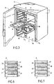
- Fig. 3 is a partial perspective view of an exemplary embodiment of a transport cart according to the invention.
- Figs. 4 and 5 are perspective views on a large scale showing a system for controlling the movement of the mobile assembly, respectively in the inactive and active position.
- Figs. 6 and 7 are schematic cross-sectional views of a device equipped with a carriage and showing the mobile assembly, respectively in its inactive and active position.
- the subject of the invention relates to an installation 1 adapted to keep cold and to warm up dishes placed on meal trays 2 .
- This installation 1 comprises a generally fixed device or terminal 3 for producing cold and heat to which is intended to be connected at least one isothermal carriage 4 for transporting and distributing meal trays 2 .
- the carriage 4 comprises a thermally insulating envelope 5 , conventionally mounted on rollers 6 .
- the envelope 5 internally delimits an enclosure 7 accessible by at least one door 8 .
- the enclosure 7 is provided with means 9 for supporting and guiding the meal trays 2 .
- the support and guide means 9 are formed by superimposed grooves, formed on the walls of the envelope 5 and whose number makes it possible to fix the storage capacity of the carriage.
- the transport carriage 4 is produced in accordance with patent FR 2 713 063.
- the carriage 4 comprises, inside the enclosure 7 , a partition 11 , thermally insulating, extending vertically and delimiting, on either side, a so-called cold compartment 13 and a so-called hot compartment 14 .
- Such a carriage 4 is intended to receive, preferably, a meal tray 2 , as described in patent FR 2 713 063.
- a meal tray 2 has a slot 15 extended by a connecting part 16 , between a zone 17 of the so-called cold plate, reserved in particular for cold dishes, and a zone 18 of the so-called hot plate, reserved for hot dishes.
- the cold zones 17 of the plates are intended to be placed in the cold compartment 13 , while the hot zones 18 of the plates are placed in the hot compartment 14 .
- the dimensions of the slot 15 are adapted, so as to allow the engagement of each plate over the entire length of the slot until the connecting portion 16 abuts against the front face 11 1 of the partition wall 11 .
- the partition is arranged to comprise, on its front face 11 1 , housings 19 superimposed, adapted to each receive a connecting portion 16 of a meal tray.
- the device 3 is constituted by means of a frame or a supporting structure 21 arranged to delimit at least one housing 22 for receiving an insulated carriage 4 .
- the supporting structure 21 thus has, in cross section, a general "C" shaped profile delimiting the housing 22 which opens by a front face 23 from which a carriage 4 can be engaged.
- the support structure 21 includes a vertically movable element 25 .
- the movable assembly 25 comprises a support frame 26 constituted by two crosspieces 27 connected together by two slides 28 extending vertically and guided in vertical translation by means of slides 30 .
- This support frame 26 is equipped with a vertically extending wall or partition 31 whose dimensions are adapted to close the enclosure 7 , that is to say in the example illustrated, the compartments 13 and 14 of a carriage 4 .
- This closure wall 31 thus delimits the rear part of the receiving housing 22 and constitutes an abutment surface for the carriage 4 and, more precisely, for its front face 5 1 in which the compartments 13, 14 open .
- the closure wall 31 is equipped with heating plates 33 mounted, in a superimposed fashion, in overhang to each extend inside the reception housing 22 and, as will be explained in the following description , below the hot zone 18 of each meal tray 2 .
- Each heating plate 33 is of the heating resistance or induction type. The operation of the heating plates 33 is controlled by means of control means, not shown but known per se.
- the closure wall 31 comprises a series of orifices 37 connected to a source of production of cold air not shown and the operation of which is controlled by known control means in itself.
- the orifices 37 are distributed over the closure wall 31 so as to open, when a carriage 4 is present , between the meal trays 2 , in each of the compartments 13 and 14 .
- each air outlet orifice 37 is connected to a source of production of cold air by means of supply pipes 38 ( fig. 6-7 ).
- the source of production of cold air is mounted on the movable assembly, that is to say, for example, on the support frame 26 .
- the quantity of cold delivered by the orifices 37 inside the compartments 13 , 14 takes account of the difference in charge existing between the hot compartment 14 and the cold compartment 13 .
- the orifices 37 , opening into the hot compartment 14 have a cross section greater than that of those opening into the cold compartment 13 .
- the mobile assembly 25 is equipped with a means 40 ensuring its vertical translation making it possible to place the crew 25 in a first position, called inactive ( FIGS. 1 and 6 ), authorizing the brought or free removal of the carriage 4 relative to the device 3 and, in a second position, called active ( Fig. 2 and 7 ), ensuring the contacting of each heating plate 33 with the underside of the associated meal tray 2 .
- the displacement means 40 of the movable assembly 25 is constituted by a lever system 41 comprising, for example, two levers 41 each connected, at one of their ends, by an operating bar 43 and articulated , at the other of their ends, on a pivot axis 44 mounted on a yoke 45 presented by the support structure 21 .
- the end of each articulated lever 42 is provided with a support roller 48 intended to cooperate with a shoe 49 fitted to each slide 28 of the movable assembly.
- the lever system is intended to occupy a first position in which the moving element 25 is in the low position and the operating bar 43 extends at a higher level relative to the top of the carriage 4 to allow free access to the device 3 for a carriage 4 .
- each lever 41 acts on the associated slide 28 , so as to raise the mobile assembly 25 , so that it occupies a second position in which the maneuvering bar 43 comes into support on the rear face 5 2 of the carriage, opposite the front face 5 1 provided with the access door 8 .
- the carriage 4 is thus locked relative to the fixed device 3 , using the operating bar 43 .
- the levers 41 can be associated with compensation springs, not shown.
- the device 3 In the high or inactive position of the displacement means 40 , the device 3 is adapted to accommodate a trolley whose dishes must firstly be kept cold and, secondly, undergo, for at least some, a setting in temperature. To this end, after opening the access door 8 , a carriage 4 is engaged inside the receiving housing 22 of the device 3 with its front face 5 1 directed towards the closure plate 31 . Such movement of the carriage 4 in the direction of the arrow f 1 makes it possible to bring the carriage into contact with the closure wall 31 .
- each heating plate 33 thus extends inside the hot compartment 14 of the carriage, below a meal tray 2 and, more precisely, of the hot part 18 .
- the operating bar 43 is lowered, so as to allow the mobile assembly 25 to rise, leading to the contacting of each heating plate 33 with the underside or the underside of a meal tray 2 ( fig. 7 ).
- the carriage 4 is locked relative to the fixed device 3 by the presence of the control bar 43 extending on the rear wall of the carriage 4 .
- control means can be controlled to ensure the operation of the source for producing cold air which is injected inside the hot 14 and cold compartments 13 allowing the dishes to be kept cold for a fixed period.
- the orifices 37 can be arranged so as to blow cold air over the upper part of the meal trays when the moving element 25 occupies its high or active position.
- the heating plates 33 are controlled in operation, so as to ensure a rise in temperature of the food contained in the hot compartment. It should be noted that, taking into account the contact made between the underside of each meal tray 2 and the associated heating plate 33 , good thermal conductivity can be obtained for heating dishes. After the heating plates 33 have stopped, the operating bar 43 can be raised so as to lower the moving element 25 . The heating plates 33 are thus released from the meal trays ( FIG. 6 ) authorizing the withdrawal of the carriage 4 from the fixed device 3 .
- the installation 1 according to the invention therefore has the advantage of proposing a fixed device 3 of simple design, adapted to allow easy connection for a trolley 4 for transporting meal trays.
- the use of a mobile assembly 25 on the fixed device 3 ensures secure contact between the hot plates 33 and the meal trays 2 . This results in good thermal conductivity for bringing food to temperature, avoiding heat loss.
- the partition 11 divides the enclosure 7 of the carriage 4 into a hot compartment 14 and a cold compartment 13 , it is possible to obtain an effective heating of the dishes, while maintaining at cold temperature the food placed in the cold compartment 13 .
- closure wall 31 may be equip by means of a seal 50 intended to cooperate with the front wall 11 1 of the partition 11 .
- a seal 50 intended to cooperate with the front wall 11 1 of the partition 11 .
Landscapes
- Engineering & Computer Science (AREA)
- Food Science & Technology (AREA)
- Devices For Warming Or Keeping Food Or Tableware Hot (AREA)
- Battery Mounting, Suspending (AREA)
- Catching Or Destruction (AREA)
- Body Washing Hand Wipes And Brushes (AREA)
- Warehouses Or Storage Devices (AREA)
- Baking, Grill, Roasting (AREA)
- Commercial Cooking Devices (AREA)
Claims (12)
- Vorrichtung zum Kühlhalten und Erwärmen von auf Serviertabletts (2) gestellte Speisen, wobei die Vorrichtung (3) folgendes aufweist:dadurch gekennzeichnet, dass die Tragstruktur (21) ein vertikal bewegliches Organ (25) trägt, das eine Verschlusswand (31) aufweist, welche den Raum (7) des isothermen Wagens verschließen soll und mit folgendem ausgestattet ist:eine Tragstruktur (21), die wenigstens einen Aufnahmeraum (22) für einen isothermen Wagen (4) mit einem isolierenden Gehäuse (5) begrenzt, das im Inneren einen Raum (7) begrenzt, der über wenigstens eine Tür (8) zugänglich ist, die in geöffneter Stellung mit der Aufnahme (22) in Verbindung steht, wobei der Raum mit Haltemitteln (9) versehen ist, die ermöglichen, die Serviertabletts (2) in übereinander angeordneter Position zu halten,eine Quelle zum Erzeugen kalter Luft, die geeignet ist, bei Vorhandensein eines isothermen Wagens (4) die in den Raum gestellten Speisen kühl zu halten,übereinander angeordnete Heizplatten (33), um bei Vorhandensein des isothermen Wagens einige der in den Raum gestellten Speisen zu erwärmen,und Steuermittel, die ermöglichen, den Betrieb der Quelle zum Erzeugen kalter Luft und der Heizplatten (33) zu steuern,Heizplatten (33), die vorragend angeordnet sind, um sich in den Raum des Wagens zu erstrecken,einer Reihe von Öffnungen (37), die mit der Quelle zum Erzeugen kalter Luft verbunden und über die Verschlusswand verteilt sind, um zwischen den Serviertabletts in den Raum zu münden,und einem Mittel (40) zum Bewegen des beweglichen Organs (25), das ermöglicht, es in eine erste Position zu bringen, die das Zuführen oder Zurückziehen des Wagens gegenüber der Verschlusswand (31) gestattet, sowie in eine zweite Position, die zulässt, jede Heizplatte (33) mit der Unterseite des zugeordneten Serviertabletts (2) in Kontakt zu bringen.
- Vorrichtung nach Anspruch 1, dadurch gekennzeichnet, dass das Mittel (40) zum Bewegen des beweglichen Organs von einem Hebelsystem (41) gebildet ist, welches in der zweiten Position ein Verriegeln des isothermen Wagens gegenüber der Verschlusswand sicherstellt.
- Vorrichtung nach Anspruch 2, dadurch gekennzeichnet, dass das Hebelsystem zwei gelenkige Hebel (41) aufweist, die jeweils an dem einen ihrer Enden über eine Betätigungsstange (43) verbunden sind, die an der Rückwand (52) des isothermen Wagens zur Anlage kommen soll, welche derjenigen (51) gegenüberliegt, die mit der Zugangstür (8) versehen ist.
- Vorrichtung nach Anspruch 3, dadurch gekennzeichnet, dass die Hebel (41) an der Tragstruktur (21) gelenkig angebracht sind, so dass sich in der ersten Position die Betätigungsstange (43) in einer über der Oberseite des Wagens befindlichen Höhe erstreckt, um dessen ungehindertes Zuführen oder Zurückziehen zu ermöglichen.
- Vorrichtung nach Anspruch 3 oder 4, dadurch gekennzeichnet, dass jeder Hebel (41) über sein Ende, welches dem mit der Betätigungsstange (43) verbundenen Ende gegenüberliegt, auf einen Schieber (28) wirkt, der durch Führungen (30) in senkrechter Bewegung geführt wird.
- Vorrichtung nach Anspruch 1, dadurch gekennzeichnet, dass die Verschlusswand (31) eine Dichtung (50) aufweist, die mit der Stirnwand einer Trennwand (11) zusammenwirken soll, welche innerhalb des Raumes (7) des Wagens angebracht ist und auf beiden Seiten ein Kaltfach (13) und ein Warmfach (14) begrenzt.
- Vorrichtung nach Anspruch 1, dadurch gekennzeichnet, dass die Öffnungen (37) über Zuführungsrohre (38) mit der Quelle zum Erzeugen kalter Luft verbunden sind.
- Vorrichtung nach den Ansprüchen 6 und 7, dadurch gekennzeichnet, dass die Öffnungen (37), die in das Warmfach (14) münden, einen größeren Querschnitt aufweisen, als diejenigen, welche in das Kaltfach (13) münden.
- Vorrichtung nach Anspruch 1 oder 7, dadurch gekennzeichnet, dass die Kälteerzeugungsquelle an dem beweglichen Organ (25) angebracht ist.
- Vorrichtung nach Anspruch 6, dadurch gekennzeichnet, dass die Verschlusswand (31) eine Umfangsdichtung aufweist, die mit der den Raum (7) begrenzenden Vorderseite (51) des Wagens zusammenwirken soll.
- Einrichtung zum Kühlhalten und Erwärmen von auf Serviertabletts (2) gestellte Speisen, mit:wenigstens einer Vorrichtung (3) nach einem der Ansprüche 1 bis 10,und wenigstens einem isothermen Wagen (4) mit einem isolierenden Gehäuse (5), das im Inneren einen Raum (7) begrenzt, der über wenigstens eine Tür (8) zugänglich und mit Haltemitteln (9) versehen ist, die ermöglichen, Serviertabletts (2) in übereinander angeordneter Position zu halten.
- Einrichtung nach Anspruch 11, dadurch gekennzeichnet, dass der isotherme Wagen (4) eine Trennwand (11) aufweist, die im Inneren des Raumes angebracht ist und auf beiden Seiten ein Kaltfach (13) und ein Warmfach (14) begrenzt, die Trennwand (11) übereinander liegende Aufnahmen (19) aufweist, die angepasst sind, jeweils ein Verbindungsteil (16) zwischen dem warmen und dem kalten Teil eines Serviertabletts (2) aufzunehmen, die sich in dem Warmfach bzw. Kaltfach befinden und sich auf beiden Seiten eines in die Trennwand (11) eingeführten Schlitzes (15) erstrecken.
Applications Claiming Priority (2)
| Application Number | Priority Date | Filing Date | Title |
|---|---|---|---|
| FR0000236 | 2000-01-10 | ||
| FR0000236A FR2803653B1 (fr) | 2000-01-10 | 2000-01-10 | Dispositif pour le maintien au froid et la mise en temperature de plateaux-repas et installation mettant en oeuvre un tel dispositif |
Publications (2)
| Publication Number | Publication Date |
|---|---|
| EP1116465A1 EP1116465A1 (de) | 2001-07-18 |
| EP1116465B1 true EP1116465B1 (de) | 2004-05-19 |
Family
ID=8845740
Family Applications (1)
| Application Number | Title | Priority Date | Filing Date |
|---|---|---|---|
| EP01420004A Expired - Lifetime EP1116465B1 (de) | 2000-01-10 | 2001-01-10 | Vorrichtung zum Kühlhalten und Erwärmen von Serviertabletts und Anlage zur Verwendung einer solchen Vorrichtung |
Country Status (4)
| Country | Link |
|---|---|
| EP (1) | EP1116465B1 (de) |
| AT (1) | ATE266958T1 (de) |
| DE (1) | DE60103308T2 (de) |
| FR (1) | FR2803653B1 (de) |
Cited By (2)
| Publication number | Priority date | Publication date | Assignee | Title |
|---|---|---|---|---|
| EP2581004A1 (de) | 2011-10-14 | 2013-04-17 | HUPFER Metallwerke GmbH & Co. KG | Vorrichtung zum Regenerieren von Speisen |
| US11730263B2 (en) | 2021-07-02 | 2023-08-22 | Regethermic Canada Inc. | System for storing and delivering food trays |
Families Citing this family (2)
| Publication number | Priority date | Publication date | Assignee | Title |
|---|---|---|---|---|
| DE102006057807B3 (de) * | 2006-12-06 | 2008-01-31 | Döhler & Gerweck Entwicklungs- und Montagetechnik GmbH | Vorrichtung zum Bereitstellen temperierter Lebensmittel |
| DE102007042730B3 (de) * | 2007-09-07 | 2008-09-18 | Hupfer Metallwerke Gmbh & Co. Kg | Andockstation mit kühlbaren Heizplatten |
Family Cites Families (8)
| Publication number | Priority date | Publication date | Assignee | Title |
|---|---|---|---|---|
| DE2347512A1 (de) * | 1973-09-21 | 1975-04-10 | Kueppersbusch | Vorrichtung zum auftauen und erhitzen von tiefgekuehlten, in behaeltern aufbewahrten speisen |
| US3975393A (en) | 1974-05-10 | 1976-08-17 | The Dow Chemical Company | Certain 2-pyridyl-phosphonamidothioates and derivatives thereof |
| DE2711088A1 (de) * | 1975-03-20 | 1978-09-28 | Souder | Verfahren und vorrichtung zum erwaermen von nahrungsmitteln sowie karren zum transportieren vorbereiteter nahrungsmittel |
| FR2420947A1 (fr) | 1978-03-31 | 1979-10-26 | Baudino Etienne | Appareil et plateaux pour conserver au froid et pour rechauffer eventuellement des denrees comestibles |
| FR2442035A1 (fr) * | 1978-11-24 | 1980-06-20 | Beizermann Michel | Perfectionnements aux moyens permettant de distribuer des repas |
| FR2562783B1 (fr) | 1984-04-17 | 1987-08-28 | Hervieu Michel | Ensemble de chariots et de bornes de mise en temperature en particulier pour service de repas collectifs |
| FR2713063B1 (fr) | 1993-12-03 | 1996-03-01 | Electro Calorique | Plateau-repas et appareil isotherme destiné à recevoir un tel plateau-repas. |
| DE29601788U1 (de) * | 1996-02-05 | 1996-05-02 | Ratiotherm Gmbh | Einrichtung zum induktiven Erwärmen von Speisen |
-
2000
- 2000-01-10 FR FR0000236A patent/FR2803653B1/fr not_active Expired - Fee Related
-
2001
- 2001-01-10 AT AT01420004T patent/ATE266958T1/de not_active IP Right Cessation
- 2001-01-10 EP EP01420004A patent/EP1116465B1/de not_active Expired - Lifetime
- 2001-01-10 DE DE60103308T patent/DE60103308T2/de not_active Expired - Lifetime
Cited By (4)
| Publication number | Priority date | Publication date | Assignee | Title |
|---|---|---|---|---|
| EP2581004A1 (de) | 2011-10-14 | 2013-04-17 | HUPFER Metallwerke GmbH & Co. KG | Vorrichtung zum Regenerieren von Speisen |
| DE102011054513A1 (de) | 2011-10-14 | 2013-04-18 | Hupfer Metallwerke Gmbh & Co. Kg | Vorrichtung zum Regenerieren von Speisen |
| DE102011054513B4 (de) * | 2011-10-14 | 2020-10-29 | Hupfer Metallwerke Gmbh & Co. Kg | Vorrichtung zum Regenerieren von Speisen |
| US11730263B2 (en) | 2021-07-02 | 2023-08-22 | Regethermic Canada Inc. | System for storing and delivering food trays |
Also Published As
| Publication number | Publication date |
|---|---|
| ATE266958T1 (de) | 2004-06-15 |
| DE60103308D1 (de) | 2004-06-24 |
| EP1116465A1 (de) | 2001-07-18 |
| FR2803653A1 (fr) | 2001-07-13 |
| FR2803653B1 (fr) | 2002-04-19 |
| DE60103308T2 (de) | 2005-06-02 |
Similar Documents
| Publication | Publication Date | Title |
|---|---|---|
| EP0717946B1 (de) | Verfahren zum Erwärmen von zuvor zubereiteten Fertiggerichten, Transport- und Aufwärmewagen und Tablett für Fertiggerichte sowie Tablett für zuvor zubereitete Fertiggerichte | |
| FR2677000A1 (fr) | Conditionnement calorifuge pour le transport refrigere ou chaud de recipients contenant des produits alimentaires. | |
| CA2400235A1 (fr) | Dispositif modulable pour la conservation et le rechauffement de plateaux-repas | |
| EP1116465B1 (de) | Vorrichtung zum Kühlhalten und Erwärmen von Serviertabletts und Anlage zur Verwendung einer solchen Vorrichtung | |
| CA2289584A1 (fr) | Installation pour la conservation froide avec rechauffage localise de mets sur des plateaux-repas | |
| FR2906121A1 (fr) | Installation pour permettre le raccordement a une borne fixe de deux chariots de transport de plateaux-repas | |
| FR2745984A1 (fr) | Unite et installation de moulage et de traitement thermique de produits alimentaires | |
| FR2760826A1 (fr) | Chariot refrigere et installation de rechargement en agent refrigerant | |
| EP0656186B1 (de) | Fertiggerichttablett und Temperiervorrichtung zur Aufnahme solcher Tabletts | |
| FR2604882A1 (fr) | Unite individuelle de conservation et de rechauffement des repas pour leur distribution anticipee dans les collectivites | |
| EP0161178A1 (de) | Fahrbare Muffelteile ankoppelbar an Wärme- und Kühleinheiten für Fertiggerichte | |
| EP1443838B1 (de) | Vorrichtung zur erwärmung von lebensmitteln mit doppeltem flüssigkeitskreislauf zur speicherung von wärme und kälte | |
| EP2225518B1 (de) | Zeolit-dehydrierungseinheit | |
| FR2680459A1 (fr) | Dispositif pour le transport et la distribution de plateaux repas avec remise en temperature des aliments par four micro-ondes. | |
| FR3061642A1 (fr) | Chariot de maintien et de remise en temperature d'aliments | |
| EP1775216B1 (de) | Selbstreinigender Wagen zum Transport und Verteilen von Essen auf Tabletts | |
| EP1584876B1 (de) | Speisetransportwagen mit doppelter, mitgeführter Kältereserve | |
| EP0072336A1 (de) | Vorrichtung zum Aufwärmen von Nahrungsmitteln auf einzelnen Tabletts | |
| EP0955854B1 (de) | Thermische bearbeitungseinheit für nahrungsmittel | |
| FR2770630A1 (fr) | Armoire de conservation de denrees | |
| FR2735852A1 (fr) | Chariot isotherme et installation pour assurer le refroidissement de chariots isothermes | |
| EP2315996B1 (de) | Vorrichtung zur montage eines lüfters für eine kühleinheit | |
| FR2878236A1 (fr) | Chariot isotherme comportant des moyens mobiles embarques de production de froid | |
| FR2755359A1 (fr) | Armoire de conservation froide avec remise en temperature de plats cuisines sur des plateaux-repas | |
| FR2727838A1 (fr) | Procede de remise en temperature, chariot de transport et de remise en temperature, et plateau de reception de plats cuisines a l'avance |
Legal Events
| Date | Code | Title | Description |
|---|---|---|---|
| PUAI | Public reference made under article 153(3) epc to a published international application that has entered the european phase |
Free format text: ORIGINAL CODE: 0009012 |
|
| AK | Designated contracting states |
Kind code of ref document: A1 Designated state(s): AT BE CH CY DE DK ES FI FR GB GR IE IT LI LU MC NL PT SE TR |
|
| AX | Request for extension of the european patent |
Free format text: AL;LT;LV;MK;RO;SI |
|
| 17P | Request for examination filed |
Effective date: 20011210 |
|
| AKX | Designation fees paid |
Free format text: AT BE CH CY DE DK ES FI FR GB GR IE IT LI LU MC NL PT SE TR |
|
| GRAP | Despatch of communication of intention to grant a patent |
Free format text: ORIGINAL CODE: EPIDOSNIGR1 |
|
| GRAS | Grant fee paid |
Free format text: ORIGINAL CODE: EPIDOSNIGR3 |
|
| GRAA | (expected) grant |
Free format text: ORIGINAL CODE: 0009210 |
|
| AK | Designated contracting states |
Kind code of ref document: B1 Designated state(s): AT BE CH CY DE DK ES FI FR GB GR IE IT LI LU MC NL PT SE TR |
|
| PG25 | Lapsed in a contracting state [announced via postgrant information from national office to epo] |
Ref country code: IT Free format text: LAPSE BECAUSE OF FAILURE TO SUBMIT A TRANSLATION OF THE DESCRIPTION OR TO PAY THE FEE WITHIN THE PRESCRIBED TIME-LIMIT;WARNING: LAPSES OF ITALIAN PATENTS WITH EFFECTIVE DATE BEFORE 2007 MAY HAVE OCCURRED AT ANY TIME BEFORE 2007. THE CORRECT EFFECTIVE DATE MAY BE DIFFERENT FROM THE ONE RECORDED. Effective date: 20040519 Ref country code: TR Free format text: LAPSE BECAUSE OF FAILURE TO SUBMIT A TRANSLATION OF THE DESCRIPTION OR TO PAY THE FEE WITHIN THE PRESCRIBED TIME-LIMIT Effective date: 20040519 Ref country code: FI Free format text: LAPSE BECAUSE OF FAILURE TO SUBMIT A TRANSLATION OF THE DESCRIPTION OR TO PAY THE FEE WITHIN THE PRESCRIBED TIME-LIMIT Effective date: 20040519 Ref country code: IE Free format text: LAPSE BECAUSE OF FAILURE TO SUBMIT A TRANSLATION OF THE DESCRIPTION OR TO PAY THE FEE WITHIN THE PRESCRIBED TIME-LIMIT Effective date: 20040519 Ref country code: GB Free format text: LAPSE BECAUSE OF FAILURE TO SUBMIT A TRANSLATION OF THE DESCRIPTION OR TO PAY THE FEE WITHIN THE PRESCRIBED TIME-LIMIT Effective date: 20040519 Ref country code: ES Free format text: LAPSE BECAUSE OF FAILURE TO SUBMIT A TRANSLATION OF THE DESCRIPTION OR TO PAY THE FEE WITHIN THE PRESCRIBED TIME-LIMIT Effective date: 20040519 Ref country code: AT Free format text: LAPSE BECAUSE OF FAILURE TO SUBMIT A TRANSLATION OF THE DESCRIPTION OR TO PAY THE FEE WITHIN THE PRESCRIBED TIME-LIMIT Effective date: 20040519 |
|
| REG | Reference to a national code |
Ref country code: GB Ref legal event code: FG4D Free format text: NOT ENGLISH |
|
| REG | Reference to a national code |
Ref country code: CH Ref legal event code: EP |
|
| REG | Reference to a national code |
Ref country code: IE Ref legal event code: FG4D Free format text: FRENCH |
|
| REF | Corresponds to: |
Ref document number: 60103308 Country of ref document: DE Date of ref document: 20040624 Kind code of ref document: P |
|
| PG25 | Lapsed in a contracting state [announced via postgrant information from national office to epo] |
Ref country code: GR Free format text: LAPSE BECAUSE OF FAILURE TO SUBMIT A TRANSLATION OF THE DESCRIPTION OR TO PAY THE FEE WITHIN THE PRESCRIBED TIME-LIMIT Effective date: 20040819 Ref country code: SE Free format text: LAPSE BECAUSE OF FAILURE TO SUBMIT A TRANSLATION OF THE DESCRIPTION OR TO PAY THE FEE WITHIN THE PRESCRIBED TIME-LIMIT Effective date: 20040819 Ref country code: DK Free format text: LAPSE BECAUSE OF FAILURE TO SUBMIT A TRANSLATION OF THE DESCRIPTION OR TO PAY THE FEE WITHIN THE PRESCRIBED TIME-LIMIT Effective date: 20040819 |
|
| GBV | Gb: ep patent (uk) treated as always having been void in accordance with gb section 77(7)/1977 [no translation filed] |
Effective date: 20040519 |
|
| REG | Reference to a national code |
Ref country code: IE Ref legal event code: FD4D |
|
| PG25 | Lapsed in a contracting state [announced via postgrant information from national office to epo] |
Ref country code: LU Free format text: LAPSE BECAUSE OF NON-PAYMENT OF DUE FEES Effective date: 20050110 Ref country code: CY Free format text: LAPSE BECAUSE OF FAILURE TO SUBMIT A TRANSLATION OF THE DESCRIPTION OR TO PAY THE FEE WITHIN THE PRESCRIBED TIME-LIMIT Effective date: 20050110 |
|
| PG25 | Lapsed in a contracting state [announced via postgrant information from national office to epo] |
Ref country code: CH Free format text: LAPSE BECAUSE OF NON-PAYMENT OF DUE FEES Effective date: 20050131 Ref country code: MC Free format text: LAPSE BECAUSE OF NON-PAYMENT OF DUE FEES Effective date: 20050131 Ref country code: LI Free format text: LAPSE BECAUSE OF NON-PAYMENT OF DUE FEES Effective date: 20050131 |
|
| PLBE | No opposition filed within time limit |
Free format text: ORIGINAL CODE: 0009261 |
|
| STAA | Information on the status of an ep patent application or granted ep patent |
Free format text: STATUS: NO OPPOSITION FILED WITHIN TIME LIMIT |
|
| 26N | No opposition filed |
Effective date: 20050222 |
|
| REG | Reference to a national code |
Ref country code: CH Ref legal event code: PL |
|
| PG25 | Lapsed in a contracting state [announced via postgrant information from national office to epo] |
Ref country code: PT Free format text: LAPSE BECAUSE OF NON-PAYMENT OF DUE FEES Effective date: 20041019 |
|
| PGFP | Annual fee paid to national office [announced via postgrant information from national office to epo] |
Ref country code: BE Payment date: 20100326 Year of fee payment: 10 |
|
| BERE | Be: lapsed |
Owner name: *ELECTRO ALU Effective date: 20110131 |
|
| PG25 | Lapsed in a contracting state [announced via postgrant information from national office to epo] |
Ref country code: BE Free format text: LAPSE BECAUSE OF NON-PAYMENT OF DUE FEES Effective date: 20110131 |
|
| REG | Reference to a national code |
Ref country code: FR Ref legal event code: PLFP Year of fee payment: 16 |
|
| REG | Reference to a national code |
Ref country code: FR Ref legal event code: PLFP Year of fee payment: 17 |
|
| REG | Reference to a national code |
Ref country code: FR Ref legal event code: PLFP Year of fee payment: 18 |
|
| PGFP | Annual fee paid to national office [announced via postgrant information from national office to epo] |
Ref country code: NL Payment date: 20191217 Year of fee payment: 20 |
|
| PGFP | Annual fee paid to national office [announced via postgrant information from national office to epo] |
Ref country code: FR Payment date: 20191105 Year of fee payment: 20 |
|
| PGFP | Annual fee paid to national office [announced via postgrant information from national office to epo] |
Ref country code: DE Payment date: 20200113 Year of fee payment: 20 |
|
| REG | Reference to a national code |
Ref country code: DE Ref legal event code: R071 Ref document number: 60103308 Country of ref document: DE |
|
| REG | Reference to a national code |
Ref country code: NL Ref legal event code: MK Effective date: 20210109 |