EP1115999B1 - Illumination system having an array of linear prisms - Google Patents
Illumination system having an array of linear prisms Download PDFInfo
- Publication number
- EP1115999B1 EP1115999B1 EP99949842A EP99949842A EP1115999B1 EP 1115999 B1 EP1115999 B1 EP 1115999B1 EP 99949842 A EP99949842 A EP 99949842A EP 99949842 A EP99949842 A EP 99949842A EP 1115999 B1 EP1115999 B1 EP 1115999B1
- Authority
- EP
- European Patent Office
- Prior art keywords
- illumination system
- light
- waveguide
- refractive index
- recited
- Prior art date
- Legal status (The legal status is an assumption and is not a legal conclusion. Google has not performed a legal analysis and makes no representation as to the accuracy of the status listed.)
- Expired - Lifetime
Links
- 238000005286 illumination Methods 0.000 title claims abstract description 83
- 239000007787 solid Substances 0.000 claims abstract description 18
- NIXOWILDQLNWCW-UHFFFAOYSA-N acrylic acid group Chemical group C(C=C)(=O)O NIXOWILDQLNWCW-UHFFFAOYSA-N 0.000 claims description 6
- 229920001296 polysiloxane Polymers 0.000 claims description 3
- YCKRFDGAMUMZLT-UHFFFAOYSA-N Fluorine atom Chemical compound [F] YCKRFDGAMUMZLT-UHFFFAOYSA-N 0.000 claims description 2
- 239000011248 coating agent Substances 0.000 claims description 2
- 238000000576 coating method Methods 0.000 claims description 2
- 230000008878 coupling Effects 0.000 claims description 2
- 238000010168 coupling process Methods 0.000 claims description 2
- 238000005859 coupling reaction Methods 0.000 claims description 2
- 229910052731 fluorine Inorganic materials 0.000 claims description 2
- 239000011737 fluorine Substances 0.000 claims description 2
- 239000004417 polycarbonate Substances 0.000 claims description 2
- 229920000515 polycarbonate Polymers 0.000 claims description 2
- 229920000642 polymer Polymers 0.000 claims description 2
- 230000001902 propagating effect Effects 0.000 claims 1
- 239000000463 material Substances 0.000 description 7
- 240000003380 Passiflora rubra Species 0.000 description 2
- 210000000007 bat wing Anatomy 0.000 description 2
- 230000007423 decrease Effects 0.000 description 2
- 239000004973 liquid crystal related substance Substances 0.000 description 2
- 239000004033 plastic Substances 0.000 description 2
- 239000004677 Nylon Substances 0.000 description 1
- 239000004793 Polystyrene Substances 0.000 description 1
- 239000000853 adhesive Substances 0.000 description 1
- 230000001070 adhesive effect Effects 0.000 description 1
- 238000013459 approach Methods 0.000 description 1
- 230000002238 attenuated effect Effects 0.000 description 1
- 230000002939 deleterious effect Effects 0.000 description 1
- 230000001419 dependent effect Effects 0.000 description 1
- 229910052736 halogen Inorganic materials 0.000 description 1
- 150000002367 halogens Chemical class 0.000 description 1
- 238000004519 manufacturing process Methods 0.000 description 1
- 238000012986 modification Methods 0.000 description 1
- 230000004048 modification Effects 0.000 description 1
- 229920001778 nylon Polymers 0.000 description 1
- 230000003287 optical effect Effects 0.000 description 1
- 229920000058 polyacrylate Polymers 0.000 description 1
- 229920000728 polyester Polymers 0.000 description 1
- 229920002223 polystyrene Polymers 0.000 description 1
Images
Classifications
-
- G—PHYSICS
- G02—OPTICS
- G02B—OPTICAL ELEMENTS, SYSTEMS OR APPARATUS
- G02B6/00—Light guides; Structural details of arrangements comprising light guides and other optical elements, e.g. couplings
- G02B6/0001—Light guides; Structural details of arrangements comprising light guides and other optical elements, e.g. couplings specially adapted for lighting devices or systems
- G02B6/0011—Light guides; Structural details of arrangements comprising light guides and other optical elements, e.g. couplings specially adapted for lighting devices or systems the light guides being planar or of plate-like form
- G02B6/0033—Means for improving the coupling-out of light from the light guide
- G02B6/0035—Means for improving the coupling-out of light from the light guide provided on the surface of the light guide or in the bulk of it
- G02B6/0038—Linear indentations or grooves, e.g. arc-shaped grooves or meandering grooves, extending over the full length or width of the light guide
-
- G—PHYSICS
- G02—OPTICS
- G02B—OPTICAL ELEMENTS, SYSTEMS OR APPARATUS
- G02B6/00—Light guides; Structural details of arrangements comprising light guides and other optical elements, e.g. couplings
- G02B6/0001—Light guides; Structural details of arrangements comprising light guides and other optical elements, e.g. couplings specially adapted for lighting devices or systems
- G02B6/0011—Light guides; Structural details of arrangements comprising light guides and other optical elements, e.g. couplings specially adapted for lighting devices or systems the light guides being planar or of plate-like form
- G02B6/0033—Means for improving the coupling-out of light from the light guide
- G02B6/005—Means for improving the coupling-out of light from the light guide provided by one optical element, or plurality thereof, placed on the light output side of the light guide
- G02B6/0053—Prismatic sheet or layer; Brightness enhancement element, sheet or layer
-
- G—PHYSICS
- G02—OPTICS
- G02B—OPTICAL ELEMENTS, SYSTEMS OR APPARATUS
- G02B6/00—Light guides; Structural details of arrangements comprising light guides and other optical elements, e.g. couplings
- G02B6/0001—Light guides; Structural details of arrangements comprising light guides and other optical elements, e.g. couplings specially adapted for lighting devices or systems
- G02B6/0011—Light guides; Structural details of arrangements comprising light guides and other optical elements, e.g. couplings specially adapted for lighting devices or systems the light guides being planar or of plate-like form
- G02B6/0033—Means for improving the coupling-out of light from the light guide
- G02B6/005—Means for improving the coupling-out of light from the light guide provided by one optical element, or plurality thereof, placed on the light output side of the light guide
- G02B6/0055—Reflecting element, sheet or layer
Definitions
- This invention relates to illumination systems, and more particularly, to an illumination system having an array of linear prisms located on a side of a solid waveguide opposite to which light emerges from the waveguide for controlling the light output distribution of the illumination system.
- the illumination systems disclosed in these patents are directed to backlighting of liquid crystal displays (LCDs), which require a highly collimated light output, e.g., output angles no greater than ⁇ 20°, where output angles are measured from a direction perpendicular to the plane of the output surface of the waveguide.
- LCDs liquid crystal displays
- illumination system that can accept an unrestricted light input (i.e. un-collimated or full hemisphere) and that can control the light output distribution and intensity.
- unrestricted light input i.e. un-collimated or full hemisphere
- Such illumination systems must be inexpensive to manufacture, durable and reliable.
- US-A-5390276 discloses a backlight for a liquid crystal display or, more generally, an illumination system according to the preamble of claim 1.
- the present invention is further characterized by that the included angle defines an output cut-off angle of greater than approximately ⁇ 25° for controlling the light output from said illumination system.
- the illumination system generally comprises a solid waveguide and a light directing structure located on a side opposite of the waveguide's light output side for controlling the light output distribution from the illumination system.
- the light directing structure may be unitarily formed with the waveguide or it may be secured thereto by an interface which provides approximately 100% contact between the waveguide and light directing structure.
- the light directing structure includes an array of light directing features configured as generally lenticular prisms that extend in a direction substantially perpendicular (i.e., not parallel) to the average direction at which light rays enter and propagate through the waveguide. Each light directing feature defines an included angle that controls the distribution of light output from the illumination system in a first direction.
- the interface when provided, controls the distribution of light output from the illumination system in a second direction that is generally orthogonal with respect to the first direction.
- the illumination system may also include an interface for coupling the light directing structure with approximately 100% contact to the solid waveguide and having a second refractive index that is less than the first refractive index of the solid waveguide.
- the interface controls the light output distribution from the illumination system in a second direction that is generally orthogonal with respect to the first direction.
- the present illumination system provides an illumination system with a controllable output light distribution and an ideal light output intensity that is especially well-suited for home and office applications.
- the present invention provides an illumination system having a controllable light output distribution and an intensity from an unrestricted light input source (i.e., un-collimated or full-hemisphere) and that is especially well-suited for home and office lighting applications.
- the illumination system generally includes a solid waveguide and an array of light directing features for controlling the light output from the illumination system in a single or first direction.
- An interface may be provided to optically and physically connect the waveguide and light directing features and to control the light output from the illumination system in a second direction that is generally orthogonal with respect to the first direction.
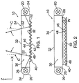
- Fig. 1 there is shown a first embodiment of an illumination system 10 that provides a controllable light output distribution from an unrestricted light input source.
- an illumination system 10 that provides a controllable light output distribution from an unrestricted light input source.
- a cut-off for light output from the illumination system 10 such that there is little or no light emitted from the illumination system at angles greater than a predetermined cut-off angle C ; preferably the cut-off angle is greater than approximately ⁇ 25 and less than approximately ⁇ 90°. Having a cut-off angle prevents the illumination systems from flooding an area with high angle light.
- a light output having a generally uniform intensity, without light “hot-spots” or concentrated points of light, and that decreases or dips when the illumination system is viewed straight on, i.e. at a viewing angle of approximately 0°.
- Such an output distribution is referred to as a "bat-wing” pattern and is provided by the present invention.
- the distribution of light output from the illumination system 10 defines an angular viewing range that is limited by the cut-off angle C , beyond which little or no light is visually detectable as emerging therefrom.
- the following detailed description will be directed to an illumination system 10 having a cut-off angle of approximately ⁇ 60°. It will be obvious to persons skilled in the art that this cut-off angular range is an illustrative and non-limiting example of the present invention and that greater or lesser cut-off angles (i.e., angular viewing ranges) are contemplated by the present invention, e.g., ranging from approximately ⁇ 25° to approximately ⁇ 90°.
- the illumination system 10 generally includes a solid waveguide 30 which is optically coupled to a light source 20 that extends longitudinally along a light input side 26 of the waveguide 30.
- Light rays 22 from the light source 20 propagate within and through the waveguide 30 and emerge therefrom through a light output side 34 having a substantially planar light output surface 32.
- a reflector 24 is provided about the light source 20 to direct light rays into the waveguide 30.
- the waveguide 30 is constructed of a clear plastic and has a first refractive index n1 that is preferably greater than 1.
- the waveguide 30 is constructed of acrylic or polycarbonate, and has a first refractive index n1 of approximately 1.49 and 1.59, respectively. While the preferred material for the waveguide 30 is acrylic, other clear plastic materials are contemplated by the present invention, including, but not limited to clear polystyrene, silicone, polyester, and nylon.
- control of light output from the illumination system 10 in the first direction refers to a direction that is generally perpendicular to the longitudinal direction of the light directing feature array 42.
- Control of light output in two directions refers to a first direction that is generally perpendicular to the longitudinal direction of the light directing feature array 42, and a second direction that is generally orthogonal with respect to the first direction.
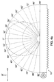
- the light output distribution has a generally "bat-wing" shape (see, e.g., Fig 4a ) and is of substantially uniform intensity within the defined output angular viewing range.
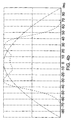
- the intensity of the light output from the illumination system 10 remains substantially constant when viewed along a plane generally perpendicular to the light input side 26 of the waveguide 30, and gradually decreases as the viewing angle along that plane approaches the cut-off angle C . This is illustrated graphically in Figs. 4a and 4b, where the cut-off angle equals approximately ⁇ 60°.
- the light output distribution of the illumination system 10 of the present invention can be controlled in the first and second directions.
- the present invention also advantageously provides a light output that is somewhat attenuated when the viewing angle is approximately 0° (see, e.g., Figs. 4a and 4b ). This reduces the deleterious effects on the viewer's eyes when looking directing into the illumination system 10.
- a light directing feature array 42 is defined on a light directing structure 40 located opposite to the light output side 34 and includes a plurality of generally lenticular prisms 48 that extend longitudinally along the waveguide 30 in a direction generally not parallel (i.e., perpendicular) to the direction at which light rays 22 enter and propagate through the waveguide 30.
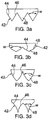
- Each prism 48 includes first and second light directing surfaces 44, 46 that are disposed with respect to each so as to define an included angle w therebetween that controls the distribution of light output from the illumination system 10 in the first direction (i.e., in a single direction that is generally perpendicular to the longitudinal direction of the prism 48).
- the included angle w controls the emergence of light rays 22 from the illumination system 10 in the first direction (i.e., in the ⁇ x -direction indicated in Fig. 4a ) so that only light rays 22 having an exit angle that is less than or equal to the desired cut-off angle C emerge from the illumination system 10.
- the desired cut-off angle is approximately ⁇ 60°.
- the included angle w is determined by the refractive index n1 (the first refractive index) of the waveguide 30 (which is determined by the material from which the waveguide 30 is made), the angular distribution of the light input to the waveguide 30 (which need not be controlled for the present invention), and the desired angular distribution of light output from the illumination system 10, i.e., the desired cut-off angle C .
- the included angle w ranges from between about 120° and 140° depending on the specified cut-off level.
- the present invention is not limited to the disclosed desired cut-off angular range of ⁇ 60°, but rather, includes cut-off angular ranges of between ⁇ 25° and ⁇ 90°.
- the light output from the illumination system 10 of the present invention may be symmetrical (e.g. ⁇ 60°), asymmetrical (e.g.+30°, -75°), or otherwise.
- the included angle w for prisms 48 having substantially straight sides (see, e.g. Fig. 3a ) and for a generally symmetrical cut-off angle (i.e., ⁇ 60°) is determined using the following equations: 90 + asin(1/ n1 ) - asin( sinC / n1 ) ⁇ w ⁇ asin(sin C / n1 ) + 90 where w is the included angle, n1 is the refractive index of the solid waveguide 30, and C is the desired cut-off angle of light output from said illumination system 10.
- the included angle preferably ranges from between approximately 120° and 140°, and is most preferably approximately 125°.
- the included angle is dependent, in part, upon the refractive index n1 of the material from which the solid waveguide 30 is fabricated.
- the light directing structure 40 is made from the same material as the waveguide 30 and has the same refractive index.
- the light directing feature array 42 defines an area on the light directing structure 40 that is less than or equal to the total area of the light directing structure 40.
- the area defined by the light directing feature array 42 is between approximately 5% and 100% of the total area of the light directing structure 40.
- a reflective coating 52 is provided on an outer surface of the light directing feature array 42 to facilitate reflection of light rays 22 within the waveguide 30 and toward the light output side 34.
- a reflector 50 may be provided near the light directing structure 40, as shown in Fig. 2 .
- the number of light sources 20 provided in the illumination system 10 of the present invention depends in part on the shape of the waveguide 30 and upon the light output requirements of the illumination system 10.
- the light source 20 may be point-like (light bulbs), or linear (fluorescent tubes), and may also comprise, by way of non-limiting example, an array of incandescent lights, light-emitting diodes, lasers, and halogen light sources arranged in any configuration.
- the light source 20 is preferably located at an edge of the waveguide 30 such that light rays 22 enter the waveguide 30 at an angle that is generally perpendicular to the angle at which the light rays 22 emerge from the illumination system 10. For example, light rays 22 enter the waveguide 30 generally along the x -axis and emerge from the illumination system 10 generally along the z-axis, as shown in Fig. 1.
- the illumination system 10 includes a solid, generally rectangular waveguide 30 and a light directing structure 40 physically and optically connected thereto by an interface 60.
- the interface 60 may be any commercially available adhesive including fluorine polymers and acrylic polymers, and other silicone or acrylic based materials.
- the interface 60 provides approximately 100% physical and optical contact between the waveguide 30 and light directing structure 40.
- the light directing structure 40 has a third refractive index n3 that is determined by the material from which the light directing structure 40 is fabricated. In a preferred embodiment, the third refractive index n3 is greater than 1.
- the angular distribution of light output from the illumination system 10 is also controlled in the second direction by the refractive index n2 of the interface 60, when provided.
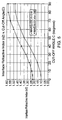
- the relationship between the refractive index n2 of the interface 60 and the cut-off angle C is defined by the equation: n2 ⁇ ( n1 2 - (cos( C )) 2 ) 1 ⁇ 2 where n2 is the refractive index of the interface 60, n1 is the refractive index of the waveguide 30, and C is the desired cut-off angle. This relationship is shown graphically in Fig. 5 .
- calculation of the included angle for controlling the output cut-off angle in the first direction is determined by the equation: where n3 is the refractive index of the light directing structure 40.
- the cut-off angle C in all directions can be selectively determined and the light output distribution of the illumination system 10 of the present invention, selectively controlled.
- each prism 48 embodiment includes first and second light directing surfaces 44, 46 that disposed with respect to each other so as to define an included angle w therebetween.
- the prisms 48 may be located in close contacting relation to each other, as shown in Figs. 3a-3d, or there may be uniform or random gaps or spaces between prisms 48.
Landscapes
- Physics & Mathematics (AREA)
- General Physics & Mathematics (AREA)
- Optics & Photonics (AREA)
- Planar Illumination Modules (AREA)
- Light Guides In General And Applications Therefor (AREA)
- Optical Elements Other Than Lenses (AREA)
- Non-Portable Lighting Devices Or Systems Thereof (AREA)
- Revetment (AREA)
- Exposure Of Semiconductors, Excluding Electron Or Ion Beam Exposure (AREA)
- Facsimile Scanning Arrangements (AREA)
Applications Claiming Priority (3)
| Application Number | Priority Date | Filing Date | Title |
|---|---|---|---|
| US160941 | 1993-12-03 | ||
| US09/160,941 US6305811B1 (en) | 1998-09-25 | 1998-09-25 | Illumination system having an array of linear prisms |
| PCT/US1999/022174 WO2000019145A1 (en) | 1998-09-25 | 1999-09-23 | Illumination system having an array of linear prisms |
Publications (2)
| Publication Number | Publication Date |
|---|---|
| EP1115999A1 EP1115999A1 (en) | 2001-07-18 |
| EP1115999B1 true EP1115999B1 (en) | 2004-06-16 |
Family
ID=22579123
Family Applications (1)
| Application Number | Title | Priority Date | Filing Date |
|---|---|---|---|
| EP99949842A Expired - Lifetime EP1115999B1 (en) | 1998-09-25 | 1999-09-23 | Illumination system having an array of linear prisms |
Country Status (10)
Families Citing this family (37)
| Publication number | Priority date | Publication date | Assignee | Title |
|---|---|---|---|---|
| EP1179158B1 (de) * | 1999-05-20 | 2003-07-09 | Zumtobel Staff GmbH | Leuchte |
| JP3730077B2 (ja) * | 2000-03-01 | 2005-12-21 | 日本板硝子株式会社 | 導光体 |
| TW503646B (en) * | 2000-03-16 | 2002-09-21 | Nippon Sheet Glass Co Ltd | Line illuminating device |
| JP4439084B2 (ja) * | 2000-06-14 | 2010-03-24 | 日東電工株式会社 | 液晶表示装置 |
| JP2002050219A (ja) * | 2000-07-25 | 2002-02-15 | Internatl Business Mach Corp <Ibm> | 面状光源装置、導光板、表示装置 |
| TW507086B (en) * | 2000-07-26 | 2002-10-21 | Shih-King Lee | Polarized separating back light source module |
| JP2002124112A (ja) * | 2000-08-07 | 2002-04-26 | Sharp Corp | バックライト及び液晶表示装置 |
| WO2002025167A1 (fr) * | 2000-09-25 | 2002-03-28 | Mitsubishi Rayon Co., Ltd. | Dispositif d'eclairage |
| JP3928395B2 (ja) * | 2001-09-21 | 2007-06-13 | オムロン株式会社 | 面光源装置 |
| JP4048049B2 (ja) * | 2001-12-21 | 2008-02-13 | 株式会社エンプラス | 面光源装置及び液晶表示装置 |
| JP4035998B2 (ja) * | 2002-01-23 | 2008-01-23 | オムロン株式会社 | 面光源装置、拡散板及び液晶表示装置 |
| KR20030085986A (ko) * | 2002-05-03 | 2003-11-07 | 나노엘시디(주) | 반사층을 가진 도광판 |
| CN100458275C (zh) * | 2002-11-29 | 2009-02-04 | 富士通株式会社 | 照明装置和液晶显示装置 |
| KR100897504B1 (ko) * | 2002-12-03 | 2009-05-15 | 삼성전자주식회사 | 백라이트 어셈블리 |
| JP3942538B2 (ja) * | 2002-12-16 | 2007-07-11 | 富士通化成株式会社 | 面照明装置と液晶表示装置 |
| TW583474B (en) * | 2003-05-12 | 2004-04-11 | Au Optronics Corp | Back light module and liquid crystal display |
| KR20050032838A (ko) * | 2003-10-02 | 2005-04-08 | 엘지.필립스 엘시디 주식회사 | 액정표시장치용 백라이트 유닛 |
| US7195374B2 (en) * | 2004-03-12 | 2007-03-27 | Honeywell International, Inc. | Luminaires for artificial lighting |
| US7258467B2 (en) * | 2004-03-12 | 2007-08-21 | Honeywell International, Inc. | Low profile direct/indirect luminaires |
| US20050201103A1 (en) * | 2004-03-12 | 2005-09-15 | Honeywell International Inc. | Luminaires with batwing light distribution |
| JP4093990B2 (ja) * | 2004-05-26 | 2008-06-04 | 日本板硝子株式会社 | 導光体、ライン照明装置および画像読取装置 |
| KR101133756B1 (ko) * | 2004-08-30 | 2012-04-09 | 삼성전자주식회사 | 도광판과 이를 구비한 백라이트 어셈블리 및 액정표시장치 |
| KR100714457B1 (ko) * | 2005-06-20 | 2007-05-04 | 한국에너지기술연구원 | 빛의 산란을 유도하는 광추출기 |
| GB2428303A (en) * | 2005-07-08 | 2007-01-24 | Sharp Kk | An illumination system for switching a display between a public and private viewing mode |
| US7452120B2 (en) * | 2006-03-24 | 2008-11-18 | Rohm And Haas Denmark Finance A/S | Illumination apparatus and film |
| EP2013538A2 (en) * | 2006-04-21 | 2009-01-14 | Koninklijke Philips Electronics N.V. | Illumination system |
| CN200968993Y (zh) * | 2006-09-20 | 2007-10-31 | 鸿富锦精密工业(深圳)有限公司 | 导光板及具有该导光板的背光模组 |
| KR100811032B1 (ko) * | 2006-10-17 | 2008-03-06 | 삼성전기주식회사 | 모노리틱 조명장치 |
| KR100903028B1 (ko) | 2007-01-15 | 2009-06-18 | 제일모직주식회사 | 쐐기형 배면프리즘을 포함하는 액정표시장치 백라이트 유닛용 도광판 |
| EP2133718A1 (en) * | 2007-03-30 | 2009-12-16 | Konica Minolta Opto, Inc. | Light source unit |
| WO2008126011A1 (en) * | 2007-04-12 | 2008-10-23 | Koninklijke Philips Electronics N.V. | Improved light guide and light-output device |
| KR101407292B1 (ko) * | 2007-06-08 | 2014-06-16 | 엘지디스플레이 주식회사 | 백라이트 유닛 |
| KR101307500B1 (ko) | 2008-08-26 | 2013-09-11 | 딩구오 판 | 반사판, 평판형 램프 및 그를 포함하는 평판형 조명용구 |
| TWI421590B (zh) * | 2010-09-17 | 2014-01-01 | Au Optronics Corp | 可切換視角的顯示器及其背光模組 |
| US10145606B2 (en) | 2011-04-26 | 2018-12-04 | Seoul Semiconductor Co., Ltd. | Product lighting refrigeration door |
| US9688190B1 (en) * | 2016-03-15 | 2017-06-27 | Ford Global Technologies, Llc | License plate illumination system |
| CA3160946A1 (en) * | 2019-12-09 | 2021-06-17 | Claudio Oliveira Egalon | Systems and methods of side illumination of waveguides |
Family Cites Families (12)
| Publication number | Priority date | Publication date | Assignee | Title |
|---|---|---|---|---|
| US5359691A (en) | 1992-10-08 | 1994-10-25 | Briteview Technologies | Backlighting system with a multi-reflection light injection system and using microprisms |
| US5390276A (en) | 1992-10-08 | 1995-02-14 | Briteview Technologies | Backlighting assembly utilizing microprisms and especially suitable for use with a liquid crystal display |
| US5428468A (en) * | 1993-11-05 | 1995-06-27 | Alliedsignal Inc. | Illumination system employing an array of microprisms |
| US5982540A (en) * | 1994-03-16 | 1999-11-09 | Enplas Corporation | Surface light source device with polarization function |
| US5671994A (en) * | 1994-06-08 | 1997-09-30 | Clio Technologies, Inc. | Flat and transparent front-lighting system using microprisms |
| JP3653308B2 (ja) * | 1995-08-01 | 2005-05-25 | 日東樹脂工業株式会社 | 面光源装置及び液晶ディスプレイ |
| KR100441548B1 (ko) * | 1996-09-23 | 2004-12-29 | 코닌클리케 필립스 일렉트로닉스 엔.브이. | 평판형화상표시장치용조사장치 |
| EP0879991A3 (en) * | 1997-05-13 | 1999-04-21 | Matsushita Electric Industrial Co., Ltd. | Illuminating system |
| US6036340A (en) * | 1998-03-03 | 2000-03-14 | Ford Global Technologies, Inc. | Dimpled manifold optical element for a vehicle lighting system |
| JP3625642B2 (ja) * | 1998-03-26 | 2005-03-02 | アルプス電気株式会社 | 液晶表示装置 |
| US6185357B1 (en) * | 1998-09-10 | 2001-02-06 | Honeywell International Inc. | Illumination system using edge-illuminated hollow waveguide and lenticular optical structures |
| US6106128A (en) * | 1998-09-11 | 2000-08-22 | Honeywell International Inc. | Illumination system having edge-illuminated waveguide and separate components for extracting and directing light |
-
1998
- 1998-09-25 US US09/160,941 patent/US6305811B1/en not_active Expired - Lifetime
-
1999
- 1999-09-23 EP EP99949842A patent/EP1115999B1/en not_active Expired - Lifetime
- 1999-09-23 CA CA002345345A patent/CA2345345A1/en not_active Abandoned
- 1999-09-23 JP JP2000572615A patent/JP2002525838A/ja active Pending
- 1999-09-23 AU AU62625/99A patent/AU6262599A/en not_active Abandoned
- 1999-09-23 AT AT99949842T patent/ATE269511T1/de not_active IP Right Cessation
- 1999-09-23 WO PCT/US1999/022174 patent/WO2000019145A1/en active IP Right Grant
- 1999-09-23 KR KR1020017003834A patent/KR100690096B1/ko not_active Expired - Fee Related
- 1999-09-23 DE DE69918143T patent/DE69918143T2/de not_active Expired - Lifetime
- 1999-09-23 CN CN99813722A patent/CN1124434C/zh not_active Expired - Fee Related
Also Published As
| Publication number | Publication date |
|---|---|
| AU6262599A (en) | 2000-04-17 |
| JP2002525838A (ja) | 2002-08-13 |
| CN1328629A (zh) | 2001-12-26 |
| WO2000019145A1 (en) | 2000-04-06 |
| KR20010075368A (ko) | 2001-08-09 |
| CN1124434C (zh) | 2003-10-15 |
| DE69918143T2 (de) | 2005-07-07 |
| KR100690096B1 (ko) | 2007-03-08 |
| DE69918143D1 (de) | 2004-07-22 |
| CA2345345A1 (en) | 2000-04-06 |
| EP1115999A1 (en) | 2001-07-18 |
| ATE269511T1 (de) | 2004-07-15 |
| WO2000019145A9 (en) | 2000-09-14 |
| US6305811B1 (en) | 2001-10-23 |
Similar Documents
| Publication | Publication Date | Title |
|---|---|---|
| EP1115999B1 (en) | Illumination system having an array of linear prisms | |
| EP1114278B1 (en) | Illumination system using an edge-illuminated hollow waveguide and lenticular optical structures | |
| US7370999B2 (en) | Light guide plate and surface light source using same | |
| US7416309B2 (en) | Optical film having a surface with rounded structures | |
| US6568822B2 (en) | Linear illumination source | |
| US6560026B2 (en) | Optical film with variable angle prisms | |
| US20060250707A1 (en) | Optical film having a surface with rounded pyramidal structures | |
| KR20190104446A (ko) | 모드-전환가능 백라이트, 개인 정보 표시 및 방법 | |
| KR20090034727A (ko) | 다중 경사들을 갖는 터닝 필름 | |
| JP2008527408A (ja) | ずらしたプリズム状構造体を備える構造化表面を有する光学フィルム | |
| KR101604243B1 (ko) | 도광판, 이를 포함한 백라이트 어셈블리 및 액정 표시 장치 | |
| GB2455057A (en) | Prismatic curved sheet optical device for use in a curved display | |
| KR20070090982A (ko) | 오목한 피라미드형 구조체가 구비된 구조화 표면을 갖는광학 필름 | |
| KR20030015378A (ko) | 구조화된 면을 구비한 백라이트 | |
| CA2708522A1 (en) | Low profile backlight apparatus | |
| US7864266B2 (en) | Diffuser plate, backlight and display having the same | |
| EP1110030B1 (en) | Illumination system having edge-illuminated waveguide and separate components for extracting and directing light | |
| JPH0921907A (ja) | プリズムシート及びそれを用いた照光装置 | |
| JPH09292531A (ja) | 導光板および光偏向板ならびに平面照明装置 | |
| KR20100129715A (ko) | 터닝 필름 시스템을 위한 광 가이드 플레이트 | |
| US5772305A (en) | Surface illuminant device | |
| JP2012033341A (ja) | 面光源装置、液晶表示装置および光学部材 | |
| KR100359877B1 (ko) | 액정표시장치용집광유닛 | |
| KR20110049732A (ko) | 신규한 액정디스플레이용 터닝 필름 | |
| US20100110342A1 (en) | Novel turning film for liquid crystal displays |
Legal Events
| Date | Code | Title | Description |
|---|---|---|---|
| PUAI | Public reference made under article 153(3) epc to a published international application that has entered the european phase |
Free format text: ORIGINAL CODE: 0009012 |
|
| 17P | Request for examination filed |
Effective date: 20010327 |
|
| AK | Designated contracting states |
Kind code of ref document: A1 Designated state(s): AT BE CH CY DE DK ES FI FR GB GR IE IT LI LU MC NL PT SE |
|
| AX | Request for extension of the european patent |
Free format text: AL;LT;LV;MK;RO;SI |
|
| 17Q | First examination report despatched |
Effective date: 20020705 |
|
| GRAP | Despatch of communication of intention to grant a patent |
Free format text: ORIGINAL CODE: EPIDOSNIGR1 |
|
| GRAS | Grant fee paid |
Free format text: ORIGINAL CODE: EPIDOSNIGR3 |
|
| GRAA | (expected) grant |
Free format text: ORIGINAL CODE: 0009210 |
|
| AK | Designated contracting states |
Kind code of ref document: B1 Designated state(s): AT BE CH CY DE DK ES FI FR GB GR IE IT LI LU MC NL PT SE |
|
| PG25 | Lapsed in a contracting state [announced via postgrant information from national office to epo] |
Ref country code: NL Free format text: LAPSE BECAUSE OF FAILURE TO SUBMIT A TRANSLATION OF THE DESCRIPTION OR TO PAY THE FEE WITHIN THE PRESCRIBED TIME-LIMIT Effective date: 20040616 Ref country code: LI Free format text: LAPSE BECAUSE OF FAILURE TO SUBMIT A TRANSLATION OF THE DESCRIPTION OR TO PAY THE FEE WITHIN THE PRESCRIBED TIME-LIMIT Effective date: 20040616 Ref country code: IT Free format text: LAPSE BECAUSE OF FAILURE TO SUBMIT A TRANSLATION OF THE DESCRIPTION OR TO PAY THE FEE WITHIN THE PRESCRIBED TIME-LIMIT;WARNING: LAPSES OF ITALIAN PATENTS WITH EFFECTIVE DATE BEFORE 2007 MAY HAVE OCCURRED AT ANY TIME BEFORE 2007. THE CORRECT EFFECTIVE DATE MAY BE DIFFERENT FROM THE ONE RECORDED. Effective date: 20040616 Ref country code: FI Free format text: LAPSE BECAUSE OF FAILURE TO SUBMIT A TRANSLATION OF THE DESCRIPTION OR TO PAY THE FEE WITHIN THE PRESCRIBED TIME-LIMIT Effective date: 20040616 Ref country code: CY Free format text: LAPSE BECAUSE OF FAILURE TO SUBMIT A TRANSLATION OF THE DESCRIPTION OR TO PAY THE FEE WITHIN THE PRESCRIBED TIME-LIMIT Effective date: 20040616 Ref country code: CH Free format text: LAPSE BECAUSE OF FAILURE TO SUBMIT A TRANSLATION OF THE DESCRIPTION OR TO PAY THE FEE WITHIN THE PRESCRIBED TIME-LIMIT Effective date: 20040616 Ref country code: BE Free format text: LAPSE BECAUSE OF FAILURE TO SUBMIT A TRANSLATION OF THE DESCRIPTION OR TO PAY THE FEE WITHIN THE PRESCRIBED TIME-LIMIT Effective date: 20040616 Ref country code: AT Free format text: LAPSE BECAUSE OF FAILURE TO SUBMIT A TRANSLATION OF THE DESCRIPTION OR TO PAY THE FEE WITHIN THE PRESCRIBED TIME-LIMIT Effective date: 20040616 |
|
| REG | Reference to a national code |
Ref country code: GB Ref legal event code: FG4D |
|
| REG | Reference to a national code |
Ref country code: CH Ref legal event code: EP |
|
| REF | Corresponds to: |
Ref document number: 69918143 Country of ref document: DE Date of ref document: 20040722 Kind code of ref document: P |
|
| REG | Reference to a national code |
Ref country code: IE Ref legal event code: FG4D |
|
| PG25 | Lapsed in a contracting state [announced via postgrant information from national office to epo] |
Ref country code: SE Free format text: LAPSE BECAUSE OF FAILURE TO SUBMIT A TRANSLATION OF THE DESCRIPTION OR TO PAY THE FEE WITHIN THE PRESCRIBED TIME-LIMIT Effective date: 20040916 Ref country code: GR Free format text: LAPSE BECAUSE OF FAILURE TO SUBMIT A TRANSLATION OF THE DESCRIPTION OR TO PAY THE FEE WITHIN THE PRESCRIBED TIME-LIMIT Effective date: 20040916 Ref country code: DK Free format text: LAPSE BECAUSE OF FAILURE TO SUBMIT A TRANSLATION OF THE DESCRIPTION OR TO PAY THE FEE WITHIN THE PRESCRIBED TIME-LIMIT Effective date: 20040916 |
|
| PG25 | Lapsed in a contracting state [announced via postgrant information from national office to epo] |
Ref country code: LU Free format text: LAPSE BECAUSE OF NON-PAYMENT OF DUE FEES Effective date: 20040923 Ref country code: IE Free format text: LAPSE BECAUSE OF NON-PAYMENT OF DUE FEES Effective date: 20040923 |
|
| PG25 | Lapsed in a contracting state [announced via postgrant information from national office to epo] |
Ref country code: ES Free format text: LAPSE BECAUSE OF FAILURE TO SUBMIT A TRANSLATION OF THE DESCRIPTION OR TO PAY THE FEE WITHIN THE PRESCRIBED TIME-LIMIT Effective date: 20040927 |
|
| PG25 | Lapsed in a contracting state [announced via postgrant information from national office to epo] |
Ref country code: MC Free format text: LAPSE BECAUSE OF NON-PAYMENT OF DUE FEES Effective date: 20040930 |
|
| LTIE | Lt: invalidation of european patent or patent extension |
Effective date: 20040616 |
|
| NLV1 | Nl: lapsed or annulled due to failure to fulfill the requirements of art. 29p and 29m of the patents act | ||
| REG | Reference to a national code |
Ref country code: CH Ref legal event code: PL |
|
| ET | Fr: translation filed | ||
| PLBE | No opposition filed within time limit |
Free format text: ORIGINAL CODE: 0009261 |
|
| STAA | Information on the status of an ep patent application or granted ep patent |
Free format text: STATUS: NO OPPOSITION FILED WITHIN TIME LIMIT |
|
| 26N | No opposition filed |
Effective date: 20050317 |
|
| REG | Reference to a national code |
Ref country code: IE Ref legal event code: MM4A |
|
| PG25 | Lapsed in a contracting state [announced via postgrant information from national office to epo] |
Ref country code: PT Free format text: LAPSE BECAUSE OF NON-PAYMENT OF DUE FEES Effective date: 20041116 |
|
| PGFP | Annual fee paid to national office [announced via postgrant information from national office to epo] |
Ref country code: GB Payment date: 20090807 Year of fee payment: 11 |
|
| PGFP | Annual fee paid to national office [announced via postgrant information from national office to epo] |
Ref country code: DE Payment date: 20090930 Year of fee payment: 11 |
|
| GBPC | Gb: european patent ceased through non-payment of renewal fee |
Effective date: 20100923 |
|
| REG | Reference to a national code |
Ref country code: FR Ref legal event code: ST Effective date: 20110531 |
|
| REG | Reference to a national code |
Ref country code: DE Ref legal event code: R119 Ref document number: 69918143 Country of ref document: DE Effective date: 20110401 |
|
| PG25 | Lapsed in a contracting state [announced via postgrant information from national office to epo] |
Ref country code: DE Free format text: LAPSE BECAUSE OF NON-PAYMENT OF DUE FEES Effective date: 20110401 Ref country code: FR Free format text: LAPSE BECAUSE OF NON-PAYMENT OF DUE FEES Effective date: 20100930 |
|
| PG25 | Lapsed in a contracting state [announced via postgrant information from national office to epo] |
Ref country code: GB Free format text: LAPSE BECAUSE OF NON-PAYMENT OF DUE FEES Effective date: 20100923 |
|
| PGFP | Annual fee paid to national office [announced via postgrant information from national office to epo] |
Ref country code: FR Payment date: 20090916 Year of fee payment: 11 |