EP1114902A2 - Device for covering the joints between floor coverings or the like - Google Patents
Device for covering the joints between floor coverings or the like Download PDFInfo
- Publication number
- EP1114902A2 EP1114902A2 EP00890350A EP00890350A EP1114902A2 EP 1114902 A2 EP1114902 A2 EP 1114902A2 EP 00890350 A EP00890350 A EP 00890350A EP 00890350 A EP00890350 A EP 00890350A EP 1114902 A2 EP1114902 A2 EP 1114902A2
- Authority
- EP
- European Patent Office
- Prior art keywords
- profile
- cover strip
- joints
- covering
- cover
- Prior art date
- Legal status (The legal status is an assumption and is not a legal conclusion. Google has not performed a legal analysis and makes no representation as to the accuracy of the status listed.)
- Granted
Links
Images

Classifications
-
- E—FIXED CONSTRUCTIONS
- E04—BUILDING
- E04F—FINISHING WORK ON BUILDINGS, e.g. STAIRS, FLOORS
- E04F19/00—Other details of constructional parts for finishing work on buildings
- E04F19/02—Borders; Finishing strips, e.g. beadings; Light coves
- E04F19/06—Borders; Finishing strips, e.g. beadings; Light coves specially designed for securing panels or masking the edges of wall- or floor-covering elements
- E04F19/065—Finishing profiles with a T-shaped cross-section or the like
- E04F19/068—Finishing profiles with a T-shaped cross-section or the like with means allowing a tipping movement
-
- E—FIXED CONSTRUCTIONS
- E04—BUILDING
- E04F—FINISHING WORK ON BUILDINGS, e.g. STAIRS, FLOORS
- E04F19/00—Other details of constructional parts for finishing work on buildings
- E04F19/02—Borders; Finishing strips, e.g. beadings; Light coves
- E04F19/06—Borders; Finishing strips, e.g. beadings; Light coves specially designed for securing panels or masking the edges of wall- or floor-covering elements
- E04F19/062—Borders; Finishing strips, e.g. beadings; Light coves specially designed for securing panels or masking the edges of wall- or floor-covering elements used between similar elements
- E04F19/063—Borders; Finishing strips, e.g. beadings; Light coves specially designed for securing panels or masking the edges of wall- or floor-covering elements used between similar elements for simultaneously securing panels having different thicknesses
-
- Y—GENERAL TAGGING OF NEW TECHNOLOGICAL DEVELOPMENTS; GENERAL TAGGING OF CROSS-SECTIONAL TECHNOLOGIES SPANNING OVER SEVERAL SECTIONS OF THE IPC; TECHNICAL SUBJECTS COVERED BY FORMER USPC CROSS-REFERENCE ART COLLECTIONS [XRACs] AND DIGESTS
- Y10—TECHNICAL SUBJECTS COVERED BY FORMER USPC
- Y10T—TECHNICAL SUBJECTS COVERED BY FORMER US CLASSIFICATION
- Y10T428/00—Stock material or miscellaneous articles
- Y10T428/19—Sheets or webs edge spliced or joined
- Y10T428/192—Sheets or webs coplanar
- Y10T428/197—Sheets or webs coplanar with noncoplanar reinforcement
-
- Y—GENERAL TAGGING OF NEW TECHNOLOGICAL DEVELOPMENTS; GENERAL TAGGING OF CROSS-SECTIONAL TECHNOLOGIES SPANNING OVER SEVERAL SECTIONS OF THE IPC; TECHNICAL SUBJECTS COVERED BY FORMER USPC CROSS-REFERENCE ART COLLECTIONS [XRACs] AND DIGESTS
- Y10—TECHNICAL SUBJECTS COVERED BY FORMER USPC
- Y10T—TECHNICAL SUBJECTS COVERED BY FORMER US CLASSIFICATION
- Y10T428/00—Stock material or miscellaneous articles
- Y10T428/24—Structurally defined web or sheet [e.g., overall dimension, etc.]
- Y10T428/24008—Structurally defined web or sheet [e.g., overall dimension, etc.] including fastener for attaching to external surface
-
- Y—GENERAL TAGGING OF NEW TECHNOLOGICAL DEVELOPMENTS; GENERAL TAGGING OF CROSS-SECTIONAL TECHNOLOGIES SPANNING OVER SEVERAL SECTIONS OF THE IPC; TECHNICAL SUBJECTS COVERED BY FORMER USPC CROSS-REFERENCE ART COLLECTIONS [XRACs] AND DIGESTS
- Y10—TECHNICAL SUBJECTS COVERED BY FORMER USPC
- Y10T—TECHNICAL SUBJECTS COVERED BY FORMER US CLASSIFICATION
- Y10T428/00—Stock material or miscellaneous articles
- Y10T428/24—Structurally defined web or sheet [e.g., overall dimension, etc.]
- Y10T428/2419—Fold at edge
- Y10T428/24198—Channel-shaped edge component [e.g., binding, etc.]
Definitions
- the invention relates to a covering device for floor covering joints or the like.
- the Can With a mounting profile and a cover strip, the Can be fastened along the joints or the like to the substrate via a web part Bracket profile at least one protruding from the web part with the cover strip has leg part which can be plugged together.
- bracket profiles with their towering leg parts form clamping elements and the cover strips with adapted to these clamping elements in arrangement and cross-section Longitudinal grooves or ribs are clamped onto the pre-assembled bracket profiles are attachable, which results in an invisible mounting option and the cover strips without separate screw connections or nailing can be reassembled and removed as required.
- the bracket profiles must be in order to achieve a sufficiently firm clamping fit stiff material, which bracket profiles so far rigid cover strips are assigned, so that with the known cover devices only straight-line joints and shoulders covered can be, however, arch-shaped courses through complex to install polygonal covers must be replaced.
- the invention is therefore based on the object of a covering device of the type described at the outset, which also provides rational covering arcuate joints or the like. Permitted and still a safe and ensures strong attachment of the cover strips using the bracket profiles.
- the invention solves this problem in that a flexible Material of the cover strip which is flexible and flexible about axes parallel to the direction of insertion is provided, the one as a support profile made of rigid material
- the individual profile pieces or if necessary Profile rails divided into pivotable sections can be the given course without difficulty, also the arched course Fasten the covering joints or heels to the subsurface, the individual profile pieces with a mutual distance in the direction of travel or tangential to an arc, and the rails with a straight course the stretched length or in the case of an arcuate course with the bow be moved according to pivoted sections.
- the rail can be made despite its manufacture rigid material with sufficient accuracy along the curve pre-assemble.
- the flexible cover strip can then be moved in a few simple steps with simultaneous bending according to the profile of the bracket Profile pieces or the profile rail are pressed on and locked in place, so that a clean joint cover or the like. Also along an arc is guaranteed.
- the incisions in the profile rail are expedient only done manually during the laying process, for which simple Cutting tools, such as secateurs, are sufficient, they could but also be prepared by the manufacturer over the entire length of the rail.
- the cover strip consists of a plasticized polyvinyl chloride (PVC), the cover strip has the desired flexible properties, the material can be dyed virtually any way it is it is possible to coat the strip with the desired decorative foils or the like.
- PVC plasticized polyvinyl chloride
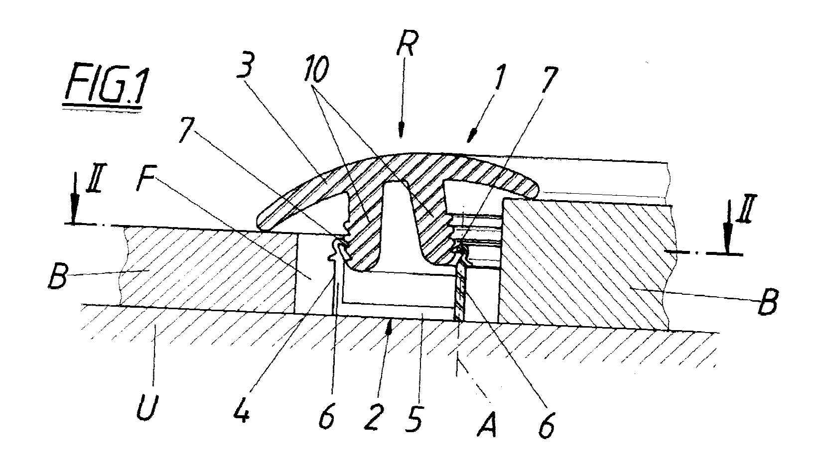
- a covering device 1 Around an arched transition joint F between two To be able to cleanly cover floor coverings B is a covering device 1 with a bracket profile 2 and a cover strip 3 are provided.
- the bracket profile 2 consists of a profile rail 4, which over a web part 5 of the joint F can be fastened along the underground U and two protruding from the web part 5 Has leg parts 6 with end clamping elements 7.
- This rail 4 made of rigid material is used in the course of laying through transverse Incisions 8 in parallel to each other parallel to the surface around vertical axes
- a pivotable sections 9 divided so that they resemble polygons can also be adapted to an arcuate course of the joint F.
- the cover strip 3 serving as a transition profile can be clamped with the profile rail 4 plug together, for which they protrude on the underside Forms longitudinal ribs 10 which snap into the clamping elements 7 of the leg parts 6 engage the profile rail 4.
- the cover strip 3 to compensate for height differences between the joint-limiting Floor coverings B also locked at an angle to the profile rail 4 become.
- the cover strip 3 is made of flexible material and is around axes parallel to plug-in direction R bendable so that they stick when plugged on can bend on the profile rail 4 following the course of the rail and a proper Coverage also for arched joints F guaranteed.
Landscapes
- Engineering & Computer Science (AREA)
- Architecture (AREA)
- Civil Engineering (AREA)
- Structural Engineering (AREA)
- Floor Finish (AREA)
- Building Environments (AREA)
- Seats For Vehicles (AREA)
Abstract
Eine Abdeckvorrichtung (1) für Bodenbelagsfugen umfaßt ein Halterungsprofil
(2) und eine Abdeckleiste (3), wobei das über einen Stegteil (5) den Fugen (F)
entlang am Untergrund (U) befestigbare Halterungsprofil (2) wenigstens einen
vom Stegteil (5) hochragenden, mit der Abdeckleiste (3) klemmend zusammensteckbaren
Schenkelteil (6) aufweist. Um die Abdeckvorrichtung auch bei einem
bogenförmigen Fugenverlauf einwandfrei einsetzen zu können, ist eine aus
biegeweichem Material bestehende und um steckrichtungsparallele Achsen
biegsame Abdeckleiste (3) vorgesehen, der als Halterungsprofil (2) eine durch
querverlaufende Einschnitte (8) in gegeneinander um steckrichtungsparallele
Achsen (A) verschwenkbare Abschnitte (9) unterteilbare Profilschiene (4) zugehört.
Description
Die Erfindung bezieht sich auf eine Abdeckvorrichtung für Bodenbelagsfugen od. dgl. mit einem Halterungsprofil und einer Abdeckleiste, wobei das über einen Stegteil den Fugen od. dgl. entlang am Untergrund befestigbare Halterungsprofil wenigstens einen vom Stegteil hochragenden, mit der Abdeckleiste klemmend zusammensteckbaren Schenkelteil aufweist.The invention relates to a covering device for floor covering joints or the like. With a mounting profile and a cover strip, the Can be fastened along the joints or the like to the substrate via a web part Bracket profile at least one protruding from the web part with the cover strip has leg part which can be plugged together.
Mit Hilfe dieser Abdeckvorrichtungen können Dehnungs- und Randfugen oder Stufenabsätze von Bodenbelägen, aber auch von Wand- und Deckenverkleidungen überbrückt und abgedeckt werden, wobei die Halterungsprofile mit ihren hochragenden Schenkelteilen Klemmelemente bilden und die Abdeckleisten mit in Anordnung und Querschnitt an diese Klemmelemente angepaßten Längsnuten oder Längsrippen auf die vormontierten Halterungsprofile klemmend aufsetzbar sind, wodurch sich eine unsichtbare Befestigungsmöglichkeit ergibt und die Abdeckleisten auch ohne gesonderte Verschraubungen oder Nagelungen montier- und bedarfsweise wieder demontierbar sind. Die Halterungsprofile müssen dabei zur Erreichung eines ausreichend festen Klemmsitzes aus entsprechend steifem Material bestehen, welchen Halterungsprofilen bisher auch biegesteife Abdeckleisten zugeordnet werden, so daß mit den bekannten Abdeckvorrichtungen nur geradlinig verlaufende Fugen und Absätze abgedeckt werden können, bogenförmige Verläufe jedoch durch aufwendig zu verlegende polygonal verlaufende Abdeckungen zu ersetzen sind.With the help of these cover devices, expansion and edge joints can be made or step heels of floor coverings, but also of wall and ceiling coverings are bridged and covered, with the bracket profiles with their towering leg parts form clamping elements and the cover strips with adapted to these clamping elements in arrangement and cross-section Longitudinal grooves or ribs are clamped onto the pre-assembled bracket profiles are attachable, which results in an invisible mounting option and the cover strips without separate screw connections or nailing can be reassembled and removed as required. The bracket profiles must be in order to achieve a sufficiently firm clamping fit stiff material, which bracket profiles so far rigid cover strips are assigned, so that with the known cover devices only straight-line joints and shoulders covered can be, however, arch-shaped courses through complex to install polygonal covers must be replaced.
Der Erfindung liegt daher die Aufgabe zugrunde, eine Abdeckvorrichtung der eingangs geschilderten Art zu schaffen, die ein rationelles Abdecken auch bogenförmig verlaufender Fugen od. dgl. erlaubt und dennoch eine sichere und belastbare Befestigung der Abdeckleisten mittels der Halterungsprofile sicherstellt.The invention is therefore based on the object of a covering device of the type described at the outset, which also provides rational covering arcuate joints or the like. Permitted and still a safe and ensures strong attachment of the cover strips using the bracket profiles.
Die Erfindung löst diese Aufgabe dadurch, daß eine aus biegeweichem Material bestehende und um steckrichtungsparallele Achsen biegsame Abdeckleiste vorgesehen ist, der als Halterungsprofil aus biegesteifem Material eine Mehrzahl einzelner Profilstücke oder eine durch querverlaufende Einschnitte in gegeneinander um steckrichtungsparallele Achsen verschwenkbare Abschnitte unterteilbare Profilschiene zugehört. Die einzelnen Profilstücke oder die bedarfsweise in verschwenkbare Abschnitte unterteilten Profilschienen lassen sich schwierigkeitslos dem vorgegebenen Verlauf, auch dem bogenförmigen Verlauf von Belagsfugen oder -absätzen folgend am Untergrund befestigen, wobei die einzelnen Profilstücke mit gegenseitigem Abstand in Verlaufsrichtung bzw. tangential zu einem Bogenverlauf, und die Profilschienen bei geradem Verlauf der gestreckten Länge nach bzw. bei bogenförmigem Verlauf mit dem Bogen entsprechend verschwenkten Abschnitten verlegt werden. Aufgrund der querverlaufenden Einschnitte, die je nach Profilgestaltung entlang der Außenkrümmung radiale Einschnitte und/oder entlang der Innenkrümmung geeignete zwikkelförmige Einschnitte sind, läßt sich die Profilschiene trotz ihrer Herstellung aus biegesteifem Material mit ausreichender Genauigkeit dem Bogenverlauf entlang vormontieren. Die biegsame Abdeckleiste kann dann mit wenigen Handgriffen unter gleichzeitigem Verbiegen entsprechend dem Halterungsprofilverlauf auf die Profilstücke bzw. die Profilschiene aufgedrückt und klemmend verrastet werden, so daß eine saubere Fugenabdeckung od. dgl. auch entlang eines Bogenverlaufes gewährleistet ist. Die Einschnitte in der Profilschiene werden zweckmäßigerweise erst im Zuge des Verlegens händisch vorgenommen, wozu einfache Schneidwerkzeuge, beispielsweise eine Gartenschere, genügen, sie könnten aber auch herstellerseitig über die ganze Schienenlänge verteilt vorbereitet sein.The invention solves this problem in that a flexible Material of the cover strip which is flexible and flexible about axes parallel to the direction of insertion is provided, the one as a support profile made of rigid material A plurality of individual profile pieces or one through transverse incisions in Sections pivotable relative to one another about axes parallel to the direction of insertion listenable dividable rail. The individual profile pieces or if necessary Profile rails divided into pivotable sections can be the given course without difficulty, also the arched course Fasten the covering joints or heels to the subsurface, the individual profile pieces with a mutual distance in the direction of travel or tangential to an arc, and the rails with a straight course the stretched length or in the case of an arcuate course with the bow be moved according to pivoted sections. Because of the transverse Incisions depending on the profile design along the outer curve radial incisions and / or suitable zig-zag along the inner curvature There are cuts, the rail can be made despite its manufacture rigid material with sufficient accuracy along the curve pre-assemble. The flexible cover strip can then be moved in a few simple steps with simultaneous bending according to the profile of the bracket Profile pieces or the profile rail are pressed on and locked in place, so that a clean joint cover or the like. Also along an arc is guaranteed. The incisions in the profile rail are expedient only done manually during the laying process, for which simple Cutting tools, such as secateurs, are sufficient, they could but also be prepared by the manufacturer over the entire length of the rail.
Besteht die Abdeckleiste aus einem weichmacherhaltigen Polyvinylchlorid (PVC), besitzt die Abdeckleiste die gewünschten biegeweichen Eigenschaften, wobei das Material praktisch beliebig gefärbt werden kann und es auch möglich ist, die Leiste mit gewünschten Dekorfolien od. dgl. zu beschichten.The cover strip consists of a plasticized polyvinyl chloride (PVC), the cover strip has the desired flexible properties, the material can be dyed virtually any way it is it is possible to coat the strip with the desired decorative foils or the like.
In der Zeichnung ist der Erfindungsgegenstand rein schematisch veranschaulicht, und zwar zeigen
- Fig. 1 und 2
- eine mit einer erfindungsgemäßen Abdeckvorrichtung abgedeckte Bodenbelagsfuge im Vertikalschnitt nach Linie I-I der Fig. 2 bzw. im Horizontalschnitt nach der Linie II-II der Fig. 1.
- 1 and 2
- a covered with a covering device according to the invention in vertical section along line II of FIG. 2 or in horizontal section along line II-II of FIG. 1st
Um eine bogenförmig verlaufende Übergangsfuge F zwischen zwei
Bodenbelägen B sauber abdecken zu können, ist eine Abdeckvorrichtung 1 mit
einem Halterungsprofil 2 und einer Abdeckleiste 3 vorgesehen. Das Halterungsprofil
2 besteht aus einer Profilschiene 4, die über einen Stegteil 5 der Fuge F
entlang am Untergrund U befestigbar ist und zwei vom Stegteil 5 hochragende
Schenkelteile 6 mit endseitigen Klemmelementen 7 aufweist. Diese Profilschiene
4 aus biegesteifem Material wird im Zuge des Verlegens durch querverlaufende
Einschnitte 8 in gegeneinander parallel zur Untergrundfläche um vertikale Achsen
A verschwenkbare Abschnitte 9 unterteilt, so daß sie polygonlinienähnlich
auch an einen bogenförmigen Verlauf der Fuge F angepaßt werden kann.Around an arched transition joint F between two
To be able to cleanly cover floor coverings B is a covering device 1 with
a bracket profile 2 and a
Die als Übergangsprofil dienende Abdeckleiste 3 läßt sich klemmend mit
der Profilschiene 4 zusammenstecken, wozu sie an der Unterseite vorragende
Längsrippen 10 bildet, die verrastend in die Klemmelemente 7 der Schenkelteile
6 der Profilschiene 4 eingreifen. Dabei kann, wie in Fig. 2 angedeutet, die Abdeckleiste
3 zum Ausgleich von Höhenunterschieden zwischen den fugenbegrenzenden
Bodenbelägen B auch schräggeneigt mit der Profilschiene 4 verrastet
werden. Die Abdeckleiste 3 besteht aus biegeweichem Material und ist um
zur Steckrichtung R parallele Achsen biegsam, so daß sie sich beim Aufstecken
auf die Profilschiene 4 dem Schienenverlauf folgend biegen läßt und eine ordnungsgemäße
Abdeckung auch bogenförmig verlaufender Fugen F gewährleistet.The
Claims (2)
Applications Claiming Priority (2)
| Application Number | Priority Date | Filing Date | Title |
|---|---|---|---|
| AT88999U | 1999-12-22 | ||
| AT0088999U AT4086U1 (en) | 1999-12-22 | 1999-12-22 | COVERING DEVICE FOR FLOORING JOINTS OD. DGL. |
Publications (3)
| Publication Number | Publication Date |
|---|---|
| EP1114902A2 true EP1114902A2 (en) | 2001-07-11 |
| EP1114902A3 EP1114902A3 (en) | 2002-07-31 |
| EP1114902B1 EP1114902B1 (en) | 2006-06-14 |
Family
ID=3502173
Family Applications (1)
| Application Number | Title | Priority Date | Filing Date |
|---|---|---|---|
| EP00890350A Expired - Lifetime EP1114902B1 (en) | 1999-12-22 | 2000-11-24 | Device for covering the joints between floor coverings or the like |
Country Status (12)
| Country | Link |
|---|---|
| US (1) | US6550205B2 (en) |
| EP (1) | EP1114902B1 (en) |
| CN (1) | CN1127600C (en) |
| AT (2) | ATE330094T1 (en) |
| CZ (1) | CZ20004728A3 (en) |
| DE (1) | DE50012979D1 (en) |
| DK (1) | DK1114902T3 (en) |
| ES (1) | ES2265905T3 (en) |
| HU (1) | HU222416B1 (en) |
| PL (1) | PL204817B1 (en) |
| PT (1) | PT1114902E (en) |
| SK (1) | SK286361B6 (en) |
Families Citing this family (38)
| Publication number | Priority date | Publication date | Assignee | Title |
|---|---|---|---|---|
| SE503861C2 (en) * | 1994-10-24 | 1996-09-23 | Perstorp Flooring Ab | Process for making a skirting board |
| US20030084634A1 (en) | 2001-11-08 | 2003-05-08 | Oliver Stanchfield | Transition molding |
| US7131242B2 (en) | 1995-03-07 | 2006-11-07 | Pergo (Europe) Ab | Flooring panel or wall panel and use thereof |
| SE9500810D0 (en) | 1995-03-07 | 1995-03-07 | Perstorp Flooring Ab | Floor tile |
| US7992358B2 (en) | 1998-02-04 | 2011-08-09 | Pergo AG | Guiding means at a joint |
| SE514645C2 (en) | 1998-10-06 | 2001-03-26 | Perstorp Flooring Ab | Floor covering material comprising disc-shaped floor elements intended to be joined by separate joint profiles |
| US7877956B2 (en) * | 1999-07-05 | 2011-02-01 | Pergo AG | Floor element with guiding means |
| SE517353C2 (en) * | 1999-12-13 | 2002-05-28 | Perstorp Flooring Ab | Transition strip on floors intended to be placed at the end of a floor unit or between two floor units |
| SE518184C2 (en) | 2000-03-31 | 2002-09-03 | Perstorp Flooring Ab | Floor covering material comprising disc-shaped floor elements which are joined together by means of interconnecting means |
| US7207143B2 (en) | 2001-11-08 | 2007-04-24 | Pergo (Europe) Ab | Transition molding and installation methods therefor |
| US20050279038A1 (en) * | 2002-07-24 | 2005-12-22 | Arbor Contract Carpet | Floor covering transition device |
| US20040055235A1 (en) * | 2002-09-19 | 2004-03-25 | Aztec Concrete Accessories, Inc. | Concrete construction with control joint protective strip |
| DE202004000706U1 (en) * | 2004-01-16 | 2004-05-13 | Herm. Friedr. Künne Gmbh & Co. | Profile rail system for checking floor coverings |
| AT505453B1 (en) * | 2004-02-27 | 2009-07-15 | Neuhofer Franz Jun | COVERING DEVICE FOR FLOOR COVERS |
| AT500734B1 (en) * | 2004-02-27 | 2009-10-15 | Neuhofer Franz Jun | DEVICE FOR BRIDGING A HIGH DIFFERENCE BETWEEN TWO FLOOR SURFACES |
| DE202004018094U1 (en) * | 2004-11-22 | 2005-02-03 | Karl Pedross Ag | Profile rail system for covering of joints between floor and/or wall coverings has base rail with upwards projecting rib with retaining head formed on end and held by retaining component with rotational movability |
| DE102006017241B4 (en) * | 2006-04-12 | 2017-11-23 | Airbus Operations Gmbh | Level gap cover for cabin linings |
| US8122665B2 (en) * | 2006-05-25 | 2012-02-28 | Pergo (Europe) Ag | Break-away multi-purpose flooring transition |
| US20080078135A1 (en) * | 2006-10-03 | 2008-04-03 | Mcintosh Jonathan | Grout member for modular flooring assemblies |
| US8484919B2 (en) * | 2006-10-18 | 2013-07-16 | Pergo (Europe) Ab | Transitions having disparate surfaces |
| WO2008058311A1 (en) * | 2006-11-14 | 2008-05-22 | Srb Constructions Technologies Pty Ltd | Moulded panel joint caulking means |
| US7797899B2 (en) * | 2007-12-07 | 2010-09-21 | Nox-Crete Products Group | Temporary floor joint filler |
| US8132380B2 (en) * | 2008-10-20 | 2012-03-13 | Wilkes Jr Robert David | Compliant trim for concrete slabs |
| CA2697573A1 (en) * | 2009-03-27 | 2010-09-27 | Pergo (Europe) Ab | Joint cover assembly and kit comprising this joint cover assembly as well as installation method therefor |
| DE102010004717A1 (en) | 2010-01-15 | 2011-07-21 | Pergo (Europe) Ab | Set of panels comprising retaining profiles with a separate clip and method for introducing the clip |
| CN104775594B (en) | 2010-05-10 | 2017-09-22 | 佩尔戈(欧洲)股份公司 | Floor panel assembly |
| CN103375018A (en) * | 2012-04-25 | 2013-10-30 | 丹阳市圣象地板配件有限公司 | Novel aluminum alloy depression bar and installing method thereof |
| US8572919B1 (en) * | 2012-08-27 | 2013-11-05 | R&L Marketing & Sales, Inc. | Floor mat system and divider for use therewith |
| US8966847B2 (en) | 2012-08-27 | 2015-03-03 | R&L Marketing & Sales, Inc. | Floor mat system and divider for use therewith |
| US9593494B2 (en) * | 2013-07-25 | 2017-03-14 | Chad Marcus Frenette | Transition strip |
| USD731078S1 (en) * | 2013-07-25 | 2015-06-02 | Chad Marcus Frenette | Transition strip |
| US9068355B1 (en) | 2015-01-05 | 2015-06-30 | Lti Flexible Products, Inc. | Floor covering transition |
| US10138639B2 (en) * | 2016-07-11 | 2018-11-27 | Unilin North America Llc | Molding assembly and floor installation |
| IT201700104860A1 (en) * | 2017-09-20 | 2019-03-20 | Progress Profiles Spa | EQUIPMENT FOR LAYING A HINGE / COVER SIEVE PROFILE AND KIT INCLUDING SUCH EQUIPMENT |
| FR3076563B1 (en) * | 2018-01-09 | 2020-06-19 | Fixat | DEFORMABLE FINISHING ACCESSORY SUITABLE FOR FORMING A JOINT BETWEEN TWO SURFACES |
| AU2019335197A1 (en) * | 2018-09-04 | 2021-04-08 | Cortex Composites, Inc. | Cementitious composite structure |
| CA3093113A1 (en) * | 2019-09-30 | 2021-03-30 | Aladdin Manufacturing Corporation | Adjustable molding assemblies and methods |
| USD1109293S1 (en) * | 2023-03-28 | 2026-01-13 | Ebbe America Lc | Shower curb cap |
Family Cites Families (13)
| Publication number | Priority date | Publication date | Assignee | Title |
|---|---|---|---|---|
| US2807826A (en) * | 1954-07-12 | 1957-10-01 | Jed Products Company | Snap-type molding and frame for carpet |
| US2996751A (en) * | 1958-09-09 | 1961-08-22 | Stanley Works | Snap-on molding |
| US3308598A (en) * | 1963-12-04 | 1967-03-14 | Textron Inc | Panel binding strip |
| US3254361A (en) * | 1964-11-16 | 1966-06-07 | William L Bonnell Company Inc | Carpet-edge binding means |
| US3777438A (en) * | 1971-08-30 | 1973-12-11 | R Brown | Ornamental protective rail |
| US4837889A (en) * | 1987-04-17 | 1989-06-13 | Kunio Saotome | Carpet retaining device |
| DE8908817U1 (en) * | 1989-07-20 | 1989-09-07 | Früh, Friedrich, 7449 Neckartenzlingen | Fastening device for a finishing strip |
| US5103612A (en) * | 1990-10-15 | 1992-04-14 | Wright Lon C | Flexible trim member |
| US5551201A (en) * | 1991-12-10 | 1996-09-03 | Anderson; Carl E. | PVC building trim |
| DE9304509U1 (en) * | 1993-03-25 | 1993-05-27 | Wedi GmbH, 4407 Emsdetten | Multi-purpose plastic strip |
| AT862U1 (en) * | 1995-08-04 | 1996-06-25 | Franz Ernst Englisch | COVER DEVICE |
| DE19646857A1 (en) * | 1996-11-13 | 1998-05-20 | Gerd Stuckenbrok | Ceiling and wall profiles for universal use in drywall |
| CA2226995A1 (en) * | 1997-01-31 | 1998-07-31 | Premark Rwp Holdings, Inc. | Molding affixed with a divider track |
-
1999
- 1999-12-22 AT AT00890350T patent/ATE330094T1/en not_active IP Right Cessation
- 1999-12-22 AT AT0088999U patent/AT4086U1/en not_active IP Right Cessation
-
2000
- 2000-11-24 EP EP00890350A patent/EP1114902B1/en not_active Expired - Lifetime
- 2000-11-24 PT PT00890350T patent/PT1114902E/en unknown
- 2000-11-24 DE DE50012979T patent/DE50012979D1/en not_active Expired - Lifetime
- 2000-11-24 DK DK00890350T patent/DK1114902T3/en active
- 2000-11-24 ES ES00890350T patent/ES2265905T3/en not_active Expired - Lifetime
- 2000-12-15 CZ CZ20004728A patent/CZ20004728A3/en unknown
- 2000-12-15 SK SK1934-2000A patent/SK286361B6/en not_active IP Right Cessation
- 2000-12-20 HU HU0004984A patent/HU222416B1/en not_active IP Right Cessation
- 2000-12-21 US US09/741,966 patent/US6550205B2/en not_active Expired - Fee Related
- 2000-12-21 PL PL344730A patent/PL204817B1/en unknown
- 2000-12-22 CN CN00136091A patent/CN1127600C/en not_active Expired - Fee Related
Also Published As
| Publication number | Publication date |
|---|---|
| HUP0004984A2 (en) | 2002-07-29 |
| US20010005539A1 (en) | 2001-06-28 |
| ATE330094T1 (en) | 2006-07-15 |
| HU0004984D0 (en) | 2001-02-28 |
| EP1114902A3 (en) | 2002-07-31 |
| PL344730A1 (en) | 2001-07-02 |
| PL204817B1 (en) | 2010-02-26 |
| SK19342000A3 (en) | 2001-08-06 |
| EP1114902B1 (en) | 2006-06-14 |
| PT1114902E (en) | 2006-10-31 |
| DK1114902T3 (en) | 2006-10-23 |
| AT4086U1 (en) | 2001-01-25 |
| CN1306138A (en) | 2001-08-01 |
| CN1127600C (en) | 2003-11-12 |
| US6550205B2 (en) | 2003-04-22 |
| CZ20004728A3 (en) | 2001-08-15 |
| SK286361B6 (en) | 2008-08-05 |
| HU222416B1 (en) | 2003-07-28 |
| DE50012979D1 (en) | 2006-07-27 |
| ES2265905T3 (en) | 2007-03-01 |
Similar Documents
| Publication | Publication Date | Title |
|---|---|---|
| EP1114902A2 (en) | Device for covering the joints between floor coverings or the like | |
| DE2837060C2 (en) | Handrail for a banister or similar, especially for a stair banister | |
| DE202005020074U1 (en) | Profile rail system | |
| DE9313697U1 (en) | Channel body | |
| DE2455775C3 (en) | Expansion joint strip for screed floors | |
| DE3212649C2 (en) | Holder for skirting boards | |
| EP0617182B1 (en) | Multi-purpose plastic strip | |
| DE926511C (en) | Device for attaching boards or the like to rungs | |
| DE10247063B3 (en) | Chamber filling device for railway tracks consists of block/rock-shaped first long and second short molded bodies of recycled old rubber | |
| DE202007000735U1 (en) | Base profile rail of a joint covering device | |
| DE3545917C2 (en) | ||
| EP1763617B1 (en) | Device for separating zones of a room | |
| DE19737893B4 (en) | Installation channel with cover and equipotential bonding clamp for equipotential bonding between them | |
| DE3505458A1 (en) | Method of producing a cavity floor | |
| EP0990747A1 (en) | Device for wall mounting a cover strip, especially for floors | |
| DE3639127A1 (en) | Means for forming an edge zone between wall and screed | |
| DE202006009045U1 (en) | Rail for striping flooring and insulation is held by height-adjustable leveling feet | |
| CH571131A5 (en) | Wall-ceiling gap elastic bar cover - with T-sectioned holder rails combining to exert tongs grip | |
| DE2432604C2 (en) | Method and device for fastening slats with a profiled cross section, in particular a sun visor, to parallel profile supports | |
| EP2025830A1 (en) | Separating strip for joints | |
| DE7440299U (en) | SUSPENSION CONSTRUCTION FOR CEILINGS | |
| DE2609456A1 (en) | Concrete coating expansion joints template - has notched joint rails locking onto rail retainers on cornice | |
| DE19806145A1 (en) | Device that can be walked on and / or driven over | |
| DE19808770A1 (en) | Shuttering for straight flights of concrete stairs | |
| DE1659281C (en) | Device for connecting a roof covering to a wall |
Legal Events
| Date | Code | Title | Description |
|---|---|---|---|
| PUAI | Public reference made under article 153(3) epc to a published international application that has entered the european phase |
Free format text: ORIGINAL CODE: 0009012 |
|
| AK | Designated contracting states |
Kind code of ref document: A2 Designated state(s): AT BE CH CY DE DK ES FI FR GB GR IE IT LI LU MC NL PT SE TR |
|
| AX | Request for extension of the european patent |
Free format text: AL;LT;LV;MK;RO;SI |
|
| PUAL | Search report despatched |
Free format text: ORIGINAL CODE: 0009013 |
|
| AK | Designated contracting states |
Kind code of ref document: A3 Designated state(s): AT BE CH CY DE DK ES FI FR GB GR IE IT LI LU MC NL PT SE TR |
|
| AX | Request for extension of the european patent |
Free format text: AL;LT;LV;MK;RO;SI |
|
| 17P | Request for examination filed |
Effective date: 20030129 |
|
| AKX | Designation fees paid |
Designated state(s): AT BE CH CY DE DK ES FI FR GB GR IE IT LI LU MC NL PT SE TR |
|
| 17Q | First examination report despatched |
Effective date: 20040528 |
|
| GRAP | Despatch of communication of intention to grant a patent |
Free format text: ORIGINAL CODE: EPIDOSNIGR1 |
|
| GRAS | Grant fee paid |
Free format text: ORIGINAL CODE: EPIDOSNIGR3 |
|
| GRAA | (expected) grant |
Free format text: ORIGINAL CODE: 0009210 |
|
| AK | Designated contracting states |
Kind code of ref document: B1 Designated state(s): AT BE CH CY DE DK ES FI FR GB GR IE IT LI LU MC NL PT SE TR |
|
| PG25 | Lapsed in a contracting state [announced via postgrant information from national office to epo] |
Ref country code: IT Free format text: LAPSE BECAUSE OF FAILURE TO SUBMIT A TRANSLATION OF THE DESCRIPTION OR TO PAY THE FEE WITHIN THE PRESCRIBED TIME-LIMIT;WARNING: LAPSES OF ITALIAN PATENTS WITH EFFECTIVE DATE BEFORE 2007 MAY HAVE OCCURRED AT ANY TIME BEFORE 2007. THE CORRECT EFFECTIVE DATE MAY BE DIFFERENT FROM THE ONE RECORDED. Effective date: 20060614 |
|
| REG | Reference to a national code |
Ref country code: GB Ref legal event code: FG4D Free format text: NOT ENGLISH |
|
| REG | Reference to a national code |
Ref country code: CH Ref legal event code: EP |
|
| REG | Reference to a national code |
Ref country code: IE Ref legal event code: FG4D Free format text: LANGUAGE OF EP DOCUMENT: GERMAN |
|
| REF | Corresponds to: |
Ref document number: 50012979 Country of ref document: DE Date of ref document: 20060727 Kind code of ref document: P |
|
| REG | Reference to a national code |
Ref country code: CH Ref legal event code: NV Representative=s name: TROESCH SCHEIDEGGER WERNER AG |
|
| REG | Reference to a national code |
Ref country code: SE Ref legal event code: TRGR |
|
| REG | Reference to a national code |
Ref country code: DK Ref legal event code: T3 |
|
| REG | Reference to a national code |
Ref country code: PT Ref legal event code: SC4A Effective date: 20060904 |
|
| REG | Reference to a national code |
Ref country code: GR Ref legal event code: EP Ref document number: 20060403183 Country of ref document: GR |
|
| PG25 | Lapsed in a contracting state [announced via postgrant information from national office to epo] |
Ref country code: MC Free format text: LAPSE BECAUSE OF NON-PAYMENT OF DUE FEES Effective date: 20061130 |
|
| GBT | Gb: translation of ep patent filed (gb section 77(6)(a)/1977) |
Effective date: 20061123 |
|
| ET | Fr: translation filed | ||
| REG | Reference to a national code |
Ref country code: ES Ref legal event code: FG2A Ref document number: 2265905 Country of ref document: ES Kind code of ref document: T3 |
|
| PLBE | No opposition filed within time limit |
Free format text: ORIGINAL CODE: 0009261 |
|
| STAA | Information on the status of an ep patent application or granted ep patent |
Free format text: STATUS: NO OPPOSITION FILED WITHIN TIME LIMIT |
|
| 26N | No opposition filed |
Effective date: 20070315 |
|
| PGFP | Annual fee paid to national office [announced via postgrant information from national office to epo] |
Ref country code: LU Payment date: 20071119 Year of fee payment: 8 |
|
| PG25 | Lapsed in a contracting state [announced via postgrant information from national office to epo] |
Ref country code: CY Free format text: LAPSE BECAUSE OF FAILURE TO SUBMIT A TRANSLATION OF THE DESCRIPTION OR TO PAY THE FEE WITHIN THE PRESCRIBED TIME-LIMIT Effective date: 20060614 |
|
| PGFP | Annual fee paid to national office [announced via postgrant information from national office to epo] |
Ref country code: DK Payment date: 20081027 Year of fee payment: 9 Ref country code: IE Payment date: 20081031 Year of fee payment: 9 Ref country code: NL Payment date: 20081127 Year of fee payment: 9 Ref country code: TR Payment date: 20081110 Year of fee payment: 9 |
|
| PGFP | Annual fee paid to national office [announced via postgrant information from national office to epo] |
Ref country code: AT Payment date: 20081127 Year of fee payment: 9 Ref country code: ES Payment date: 20081106 Year of fee payment: 9 Ref country code: FI Payment date: 20081124 Year of fee payment: 9 Ref country code: PT Payment date: 20081015 Year of fee payment: 9 |
|
| PGFP | Annual fee paid to national office [announced via postgrant information from national office to epo] |
Ref country code: IT Payment date: 20081127 Year of fee payment: 9 Ref country code: BE Payment date: 20081128 Year of fee payment: 9 Ref country code: SE Payment date: 20081112 Year of fee payment: 9 |
|
| PGFP | Annual fee paid to national office [announced via postgrant information from national office to epo] |
Ref country code: CH Payment date: 20090128 Year of fee payment: 9 Ref country code: GR Payment date: 20081027 Year of fee payment: 9 |
|
| BERE | Be: lapsed |
Owner name: *NEUHOFER FRANZ JUN. Effective date: 20091130 |
|
| REG | Reference to a national code |
Ref country code: PT Ref legal event code: MM4A Free format text: LAPSE DUE TO NON-PAYMENT OF FEES Effective date: 20100524 |
|
| REG | Reference to a national code |
Ref country code: NL Ref legal event code: V1 Effective date: 20100601 |
|
| EUG | Se: european patent has lapsed | ||
| PG25 | Lapsed in a contracting state [announced via postgrant information from national office to epo] |
Ref country code: LU Free format text: LAPSE BECAUSE OF NON-PAYMENT OF DUE FEES Effective date: 20081124 |
|
| REG | Reference to a national code |
Ref country code: CH Ref legal event code: PL |
|
| REG | Reference to a national code |
Ref country code: DK Ref legal event code: EBP |
|
| PG25 | Lapsed in a contracting state [announced via postgrant information from national office to epo] |
Ref country code: PT Free format text: LAPSE BECAUSE OF NON-PAYMENT OF DUE FEES Effective date: 20100524 |
|
| PG25 | Lapsed in a contracting state [announced via postgrant information from national office to epo] |
Ref country code: FI Free format text: LAPSE BECAUSE OF NON-PAYMENT OF DUE FEES Effective date: 20091124 Ref country code: AT Free format text: LAPSE BECAUSE OF NON-PAYMENT OF DUE FEES Effective date: 20091124 |
|
| PG25 | Lapsed in a contracting state [announced via postgrant information from national office to epo] |
Ref country code: NL Free format text: LAPSE BECAUSE OF NON-PAYMENT OF DUE FEES Effective date: 20100601 Ref country code: CH Free format text: LAPSE BECAUSE OF NON-PAYMENT OF DUE FEES Effective date: 20091130 Ref country code: LI Free format text: LAPSE BECAUSE OF NON-PAYMENT OF DUE FEES Effective date: 20091130 Ref country code: BE Free format text: LAPSE BECAUSE OF NON-PAYMENT OF DUE FEES Effective date: 20091130 Ref country code: GR Free format text: LAPSE BECAUSE OF NON-PAYMENT OF DUE FEES Effective date: 20100602 Ref country code: IE Free format text: LAPSE BECAUSE OF NON-PAYMENT OF DUE FEES Effective date: 20091124 |
|
| PG25 | Lapsed in a contracting state [announced via postgrant information from national office to epo] |
Ref country code: DK Free format text: LAPSE BECAUSE OF NON-PAYMENT OF DUE FEES Effective date: 20091130 |
|
| PG25 | Lapsed in a contracting state [announced via postgrant information from national office to epo] |
Ref country code: IT Free format text: LAPSE BECAUSE OF NON-PAYMENT OF DUE FEES Effective date: 20091124 |
|
| REG | Reference to a national code |
Ref country code: ES Ref legal event code: FD2A Effective date: 20110407 |
|
| PG25 | Lapsed in a contracting state [announced via postgrant information from national office to epo] |
Ref country code: SE Free format text: LAPSE BECAUSE OF NON-PAYMENT OF DUE FEES Effective date: 20091125 |
|
| PG25 | Lapsed in a contracting state [announced via postgrant information from national office to epo] |
Ref country code: ES Free format text: LAPSE BECAUSE OF NON-PAYMENT OF DUE FEES Effective date: 20110328 |
|
| PG25 | Lapsed in a contracting state [announced via postgrant information from national office to epo] |
Ref country code: TR Free format text: LAPSE BECAUSE OF NON-PAYMENT OF DUE FEES Effective date: 20110726 Ref country code: ES Free format text: LAPSE BECAUSE OF NON-PAYMENT OF DUE FEES Effective date: 20091125 |
|
| PG25 | Lapsed in a contracting state [announced via postgrant information from national office to epo] |
Ref country code: TR Free format text: LAPSE BECAUSE OF NON-PAYMENT OF DUE FEES Effective date: 20091124 |
|
| PGFP | Annual fee paid to national office [announced via postgrant information from national office to epo] |
Ref country code: GB Payment date: 20141126 Year of fee payment: 15 |
|
| PGFP | Annual fee paid to national office [announced via postgrant information from national office to epo] |
Ref country code: FR Payment date: 20141125 Year of fee payment: 15 |
|
| PGFP | Annual fee paid to national office [announced via postgrant information from national office to epo] |
Ref country code: DE Payment date: 20151029 Year of fee payment: 16 |
|
| GBPC | Gb: european patent ceased through non-payment of renewal fee |
Effective date: 20151124 |
|
| REG | Reference to a national code |
Ref country code: FR Ref legal event code: ST Effective date: 20160729 |
|
| PG25 | Lapsed in a contracting state [announced via postgrant information from national office to epo] |
Ref country code: GB Free format text: LAPSE BECAUSE OF NON-PAYMENT OF DUE FEES Effective date: 20151124 |
|
| PG25 | Lapsed in a contracting state [announced via postgrant information from national office to epo] |
Ref country code: FR Free format text: LAPSE BECAUSE OF NON-PAYMENT OF DUE FEES Effective date: 20151130 |
|
| REG | Reference to a national code |
Ref country code: DE Ref legal event code: R119 Ref document number: 50012979 Country of ref document: DE |
|
| PG25 | Lapsed in a contracting state [announced via postgrant information from national office to epo] |
Ref country code: DE Free format text: LAPSE BECAUSE OF NON-PAYMENT OF DUE FEES Effective date: 20170601 |