EP1114782A2 - Container with automatic straw delivery device - Google Patents
Container with automatic straw delivery device Download PDFInfo
- Publication number
- EP1114782A2 EP1114782A2 EP01105977A EP01105977A EP1114782A2 EP 1114782 A2 EP1114782 A2 EP 1114782A2 EP 01105977 A EP01105977 A EP 01105977A EP 01105977 A EP01105977 A EP 01105977A EP 1114782 A2 EP1114782 A2 EP 1114782A2
- Authority
- EP
- European Patent Office
- Prior art keywords
- straw
- extraction device
- arm
- container
- locked position
- Prior art date
- Legal status (The legal status is an assumption and is not a legal conclusion. Google has not performed a legal analysis and makes no representation as to the accuracy of the status listed.)
- Granted
Links
Images


Classifications
-
- B—PERFORMING OPERATIONS; TRANSPORTING
- B65—CONVEYING; PACKING; STORING; HANDLING THIN OR FILAMENTARY MATERIAL
- B65D—CONTAINERS FOR STORAGE OR TRANSPORT OF ARTICLES OR MATERIALS, e.g. BAGS, BARRELS, BOTTLES, BOXES, CANS, CARTONS, CRATES, DRUMS, JARS, TANKS, HOPPERS, FORWARDING CONTAINERS; ACCESSORIES, CLOSURES, OR FITTINGS THEREFOR; PACKAGING ELEMENTS; PACKAGES
- B65D77/00—Packages formed by enclosing articles or materials in preformed containers, e.g. boxes, cartons, sacks or bags
- B65D77/22—Details
- B65D77/24—Inserts or accessories added or incorporated during filling of containers
- B65D77/28—Cards, coupons, or drinking straws
- B65D77/283—Cards, coupons, or drinking straws located initially inside the container, whereby the straw is revealed only upon opening the container, e.g. pop-up straws
-
- B—PERFORMING OPERATIONS; TRANSPORTING
- B65—CONVEYING; PACKING; STORING; HANDLING THIN OR FILAMENTARY MATERIAL
- B65D—CONTAINERS FOR STORAGE OR TRANSPORT OF ARTICLES OR MATERIALS, e.g. BAGS, BARRELS, BOTTLES, BOXES, CANS, CARTONS, CRATES, DRUMS, JARS, TANKS, HOPPERS, FORWARDING CONTAINERS; ACCESSORIES, CLOSURES, OR FITTINGS THEREFOR; PACKAGING ELEMENTS; PACKAGES
- B65D17/00—Rigid or semi-rigid containers specially constructed to be opened by cutting or piercing, or by tearing of frangible members or portions
- B65D17/28—Rigid or semi-rigid containers specially constructed to be opened by cutting or piercing, or by tearing of frangible members or portions at lines or points of weakness
- B65D17/401—Rigid or semi-rigid containers specially constructed to be opened by cutting or piercing, or by tearing of frangible members or portions at lines or points of weakness characterised by having the line of weakness provided in an end wall
- B65D17/4012—Rigid or semi-rigid containers specially constructed to be opened by cutting or piercing, or by tearing of frangible members or portions at lines or points of weakness characterised by having the line of weakness provided in an end wall for opening partially by means of a tearing tab
-
- B—PERFORMING OPERATIONS; TRANSPORTING
- B65—CONVEYING; PACKING; STORING; HANDLING THIN OR FILAMENTARY MATERIAL
- B65D—CONTAINERS FOR STORAGE OR TRANSPORT OF ARTICLES OR MATERIALS, e.g. BAGS, BARRELS, BOTTLES, BOXES, CANS, CARTONS, CRATES, DRUMS, JARS, TANKS, HOPPERS, FORWARDING CONTAINERS; ACCESSORIES, CLOSURES, OR FITTINGS THEREFOR; PACKAGING ELEMENTS; PACKAGES
- B65D2517/00—Containers specially constructed to be opened by cutting, piercing or tearing of wall portions, e.g. preserving cans or tins
- B65D2517/0001—Details
- B65D2517/001—Action for opening container
- B65D2517/0014—Action for opening container pivot tab and push-down tear panel
-
- B—PERFORMING OPERATIONS; TRANSPORTING
- B65—CONVEYING; PACKING; STORING; HANDLING THIN OR FILAMENTARY MATERIAL
- B65D—CONTAINERS FOR STORAGE OR TRANSPORT OF ARTICLES OR MATERIALS, e.g. BAGS, BARRELS, BOTTLES, BOXES, CANS, CARTONS, CRATES, DRUMS, JARS, TANKS, HOPPERS, FORWARDING CONTAINERS; ACCESSORIES, CLOSURES, OR FITTINGS THEREFOR; PACKAGING ELEMENTS; PACKAGES
- B65D2517/00—Containers specially constructed to be opened by cutting, piercing or tearing of wall portions, e.g. preserving cans or tins
- B65D2517/0001—Details
- B65D2517/0047—Provided with additional elements other than for closing the opening
- B65D2517/0049—Straws, spouts, funnels, or other devices facilitating pouring or emptying
-
- B—PERFORMING OPERATIONS; TRANSPORTING
- B65—CONVEYING; PACKING; STORING; HANDLING THIN OR FILAMENTARY MATERIAL
- B65D—CONTAINERS FOR STORAGE OR TRANSPORT OF ARTICLES OR MATERIALS, e.g. BAGS, BARRELS, BOTTLES, BOXES, CANS, CARTONS, CRATES, DRUMS, JARS, TANKS, HOPPERS, FORWARDING CONTAINERS; ACCESSORIES, CLOSURES, OR FITTINGS THEREFOR; PACKAGING ELEMENTS; PACKAGES
- B65D2517/00—Containers specially constructed to be opened by cutting, piercing or tearing of wall portions, e.g. preserving cans or tins
- B65D2517/0001—Details
- B65D2517/0058—Other details of container end panel
- B65D2517/0059—General cross-sectional shape of container end panel
Definitions
- the present invention relates to a container provided with a device allowing the absorption of a drink in a hygienic way avoiding that the consumer does not put the lips on an external part of said container and more particularly the device for extracting a straw from the container.
- bottles plastics, glass bottles, metal cans, cardboard packaging can have various shapes allowing the packaging of everything type of liquid food products.
- the invention proposes by simple and inexpensive ways to solve these practical problems and hygienic thanks to an automatic straw extraction device located inside the container.
- the device comprises means for urging the straw support member intended to request it from its locked position to its free position.
- the device includes locking means for blocking the support member straw in its locked position, and unlocking means intended to release the support member from its locked position.
- the means of unlocking are constituted by a secondary unlocking arm, while the intermediate piece and the support arm are made in one holding, forming a single piece of plastic material, having some elasticity.
- the intermediate piece presents itself in the form of an annular ring.
- FIGS 1 to 11 illustrate the preferred embodiment of the straw extraction device and an alternative embodiment of said device.
- Figures 1 and 2 illustrate respectively in perspective the opening of a metal cylindrical can type container.
- Figures 3a to 3d are a block diagram of the device extraction and its operation.
- Figure 3a illustrates the device in the locked position.
- FIG. 3b illustrates the extraction device in the position of release, when it is about to be unlocked.
- FIG. 3c illustrates the device when the support member passes from its locked position to its free position.
- Figure 3d illustrates the extraction device in the free position.
- Figure 4 is a perspective bottom view illustrating the preferred embodiment of the extraction device in the free position.
- Figures 5a and 5b show a bottom view of the device extraction respectively in the locked position and in the free position, the configuration of the abutment and support surfaces of the different arms being simplified as well as the release tab to simplify the understanding of the figures.
- Figures 6a and 6b show, in perspective views different from that of FIGS. 5a and 5b, the extraction device, respectively in its locked position and in its free position.
- Figure 7a shows the extraction device from below in the locked position.
- Figure 7b illustrates in a view similar to Figure 7a the extraction device in free position.
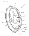
- Figure 8a shows in perspective the extraction device arranged in its cylindrical can and shows the two extreme positions of the straw support arm, the upper wall of the can represented.
- FIG. 8b illustrates in perspective the bobbin and the end of the straw extracted therefrom when the extraction device is in position free.
- FIG. 9a schematically illustrates in cross section the installation of the straw extraction device inside the can.
- Figure 9b shows in a view similar to Figure 9a, the extraction device arranged in its can.
- FIG. 9c represents a detail of FIG. 9b illustrating the sealing means of the extraction device.
- Figure 10 schematically illustrates in cross section the extraction device and its container in the free position, a portion of straw being extracted from the container.
- Figure 11 shows in perspective an alternative embodiment of the extraction device.
- the invention relates to an automatic extraction device bearing the general reference (1) intended to extract automatically when from its opening a straw (2) disposed inside a container (3).
- the extraction device (1) is advantageously described in the case particularly metallic cylindrical cans whose means opening (MO) are constituted in a manner known per se by a ring pusher (6) and a precut tab (7) which can pivot towards the interior of the container (3) under the action of the ring to release the orifice (5) said opening means, as shown in Figures 1 and 2. It goes from the automatic extraction device according to the invention could be modified to suit other types of containers or other types of opening means without leaving the scope of protection of the invention.
- the automatic extraction device (1) of the straw (2) comprises a straw support member (4) movable between a locked position (B) where the straw (2) is inside the container (3) and which corresponds to the closed position of the opening means (MO) and a free position (A) where the support member (4) has the end (2a) of the straw (2) at the orifice (5) and which corresponds to the position open said opening means.
- the device also includes biasing means (MS) of the straw support member (4) which tend to move it from its locked position (B) to its free position (A).
- locking means (MV) intended to block the straw support member (4) in its locked position (B)
- unlocking means (MDV) intended to cause the release of said organ.
- the unlocking means (MDV) are advantageously made so as to be actuated by the means opening (MO) of the container (3) when the consumer performs the opening of the orifice (5).
- the straw support member is constituted by an arm (4) carrying at its end (4a) means for retaining the straw (2) such a portion of tube (10) inside which is disposed the end (2a) of said straw.
- the straw support arm (4) is advantageously articulated on an intermediate piece (9) arranged at inside the container and secured to it by means of fixation which will be described later.
- the locking means (MV) illustrated in Figure 4 are advantageously constituted by a locking such as, for example, a secondary locking arm (8) which has at its end (8a) a set of abutment surfaces (11), namely, two lateral stops (11a, 11b) and a lower stop (11c).
- the lateral (11a, 11b) and lower (11c) abutment surfaces are intended to cooperate with complementary bearing surfaces (12, 12a, 12b, 12c) carried by the straw support arm (4) when the extraction device (1) is in the locked position (B).
- the secondary arm (8) is advantageously articulated at its other end on the intermediate piece (9), however it goes without saying that it could very well be articulated on another part integral with the bobbin (3).
- the intermediate piece (9) is made in a slightly flexible material with a certain elasticity.
- the arm support (4) and the secondary arm (8) being constituted by extensions of the intermediate piece (9), their articulation with this takes place according to a hinge (13, 14) formed in a manner known per se, for example, by a narrowing of the section of the extensions forming the arms.
- the elasticity of the material used allows the articulated arms (4, 8) to be resiliently biased towards their respective initial positions which each correspond to the free position of the extraction device (1) as shown in Figures 5b and 6b.
- the elasticity of the support arm straw (4) constantly tends to recall it to its free position (A) and thus constitutes the biasing means (MS) of the extraction device (1).
- said means could be obtained by any device equivalent elastic return, as for example located on the hinges or articulations of the arms without leaving the field of claimed protection of the invention.
- the stress on the articulated arms (4, 8) due to the elasticity of their materials when bent in the locked position (B) allows to cooperate the respective abutment and bearing surfaces (11, 12) against the forces of recall which are exerted on said arms according to a principle of flying buttresses known per se illustrated schematically in Figure 3a.
- all of said bearing and abutment surfaces allow positioning and holding the arms articulated and essentially the straw support arm (4) in a position locked (B) as shown in Figures 5a and 6a, where the end (2a) of the straw (2) which he carries is set back inside the can (3) and where the straw support arm (4) is biased towards its free position (A) thanks to its elasticity and its flexed position.
- the articulation (13) of the support arm (4) is made so that it goes from its locked position (B) where the end (2a) of the straw (2) is located in a horizontal plane (H1) located below the horizontal plane (H) comprising the orifice (5) and offset with respect to this orifice, like the show Figures 3a and 7a, towards a free position (A) where the end (2a) is arranged in a plane (H2) located slightly above the plane (H) of the orifice, directly above it, as illustrated in Figures 3d, 7b, 8b and 10.
- the displacement of the support arm (4) is thus effected by pivoting in a inclined plane orthogonal to the axis of its articulation (14) so as to allow the end (2a) of the straw (2) to pass through the orifice (5).
- the extraction device (1) also comprises means for unlocking (MDV) which allow upon actuation of the means opening (MO) of the container (3) illustrated schematically in Figure 3b of release the support arm (4) from its locked position (B).
- the unlocking means are constituted by a release tab (15) arranged on the secondary locking arm (8) and intended to be actuated when the container is opened by the pivoting inward of the can (3) of the pre-cut tongue (7) or covers opening means so as to cause the movement by pivoting around its articulation (14) of the arm secondary to an extreme release position (D) illustrated schematically Figure 3b.
- the arm secondary release (8) is also biased towards its position free (A) by additional means of solicitation obtained also by the elasticity of the material used to make it or by elastic return means located on the articulation (14) of the arm on the intermediate piece (9).
- the secondary arm (8) passes above the support arm (4) to free the bearing and abutment surfaces of the two articulated arms which cooperate. Then both arms undergo each a force to recall their respective means of solicitation and come to position in free position.
- the secondary arm of unlocking (8) overlaps the support arm (4) to pass underneath and thus allow by its own restoring force to also solicit towards the high (HA) the support arm (4) so as to bring it towards its free position (AT).
- articulated arms (4, 8), the means for retaining the straw (2), the support arm (4), the bearing and abutment surfaces, the arm secondary (8) and the intermediate part (9) are advantageously made in one piece and form a single piece which is presented under the shape of an annular ring (9) intended to be arranged inside (INT) of the bobbin (3) under the upper wall (16) on which the means for opening said can as shown in Figure 8a.
- the ring annular (9) is made of a plastic material of the type used in the food industry to be able to be placed in contact liquid intended for consumption. It can advantageously be performed by an injection process or by any other equivalent process.
- the straw (2) can consist of two coaxial portions of straw (20a, 20b), one of which (20a) is retained by the retaining means (10) of the straw support arm (4) and of which the other (20b) slides inside the first (20a) as shown in Figure 10 and allows the user to extract part of it for drinking while maintaining the lower end (2b) of the straw portion (20a) at the level of the bottom (17) of the container (3) to allow suction the entire content.
- the upper straw portion (20b) can advantageously include an annular retaining bead (18) designed to prevent it from sliding fully into the portion lower (20a).
- the bead (18) is located on the straw portion (20b) of so that its upper end (2a) is located slightly above of the plane (H) of the orifice (5) when the extraction device (1) is in the free position (A).
- the annular ring (9) can advantageously include sealing means constituted by its peripheral edge (19).
- the rim device (19) can advantageously replace silicone seals used by manufacturers to seal between the wall device (21) of the bobbin and its upper wall (16), said rim being pinched between the two walls when these are assembled assembly by crimping for example as shown in detail in the figure 9c.
- the extraction device consists of an intermediate piece (9) which can be arranged and fixed in the container and in particular in a can without the need for structural modification thereof.
- the annular ring (9) constituting it can advantageously be carried out by an injection process of the bi-material type, so as to obtain a part made from a first plastic material relatively rigid provided with a peripheral rim (19) produced in a second softer plastic material injected simultaneously with in a manner known per se.
- the relatively flexible peripheral rim allows for a perfect seal between the upper wall (16) and the wall device (21) of the bobbin (3) as shown in FIG. 9c, while the relative rigidity of the main central part allows operation optimal of the device and in particular the elastic stress of the arms of their locked position (B) where they are in a slightly flexed to their free position (A).
- the extraction device (1) comprises a straw support arm (4) articulated and biased towards its free position (A) of the type described in the previous embodiment.
- the locking means (MV) are no longer constituted by a secondary arm, but by a stop (22) in the form of a notch secured to the intermediate piece (9) on which the support arm (4) can be arranged in the locked position (B), said arm being biased by its biasing means (MS) towards its free position (AT).
- the unlocking means (MDV) consist of an unlocking tab (23) formed by a wall portion projecting from the straw support arm (4).
- This tab (23) is intended to cooperate with the precut tab (7) of the means opening (MO) of the bobbin when it rotates inward to release the support arm (4) from its stop (22) against the stress solicitation means (MS).
- the biasing means remind the arm towards its free position
- the unlocking of the arm (4) which is effected by the release tab (23) allows give the arm more potential energy than it has in the locked position since the arm (4) is moved against the return force of the biasing means (MS) of a required height to pass the notch
- the stop (22) thus makes it possible to give an energization complementary to the arm (4) in order to facilitate its positioning in position free (A) when it is released from said stop.
- the side rim (22a) of the stop (22) can advantageously be inclined and slightly curved, and can therefore constitute means for guiding the arm support (4), allowing it to be guided from its extreme position release where it comes out of the notch towards its free position.
- the support arm (4) when in the free position, is arranged in the same plane as the stop (22) and is arranged next to it.
- the mold used is a simple mold, and less expensive than in other embodiments slightly more complex and which may require the use of so-called drawer molds.
- the device extraction consists of a piece in the form of an annular ring; however according to other embodiments not shown, the device can be made in several pieces.
- the component (s) of the extraction device could have a different shape from the shape of the annular ring and have a sector or other shape for example.
- the means for fixing the annular part are constituted by the peripheral rim intended to be crimped between the cover and the peripheral wall of the can, said rim also constituting the sealing means of the device, however it goes without saying that the fastening means could have a different configuration.
- the annular part could for example not be provided with a peripheral rim but be fixed by wedging in the upper part of the bobbin which has a slightly shaped tapered.
Abstract
Description
La présente invention concerne un récipient muni d'un dispositif permettant l'absorption d'une boisson de façon hygiénique évitant que le consommateur ne pose les lèvres sur une partie externe dudit récipient et plus particulièrement le dispositif d'extraction d'une paille du récipient.The present invention relates to a container provided with a device allowing the absorption of a drink in a hygienic way avoiding that the consumer does not put the lips on an external part of said container and more particularly the device for extracting a straw from the container.
Il existe sur le marché de nombreux types de récipients : bouteilles plastiques, bouteilles en verre, canettes métalliques, emballages cartonnés pouvant avoir des formes diverses permettant le conditionnement de tout type de produits liquides alimentaires.There are many types of containers on the market: bottles plastics, glass bottles, metal cans, cardboard packaging can have various shapes allowing the packaging of everything type of liquid food products.
Ces différents récipients présentent l'inconvénient pour l'utilisateur d'être soit peu hygiéniques lorsque l'on veut boire à même le récipient, soit peu pratiques selon la forme et la dimension du goulot, voire la forme même du récipient.These different containers have the drawback for the user to be unhygienic when drinking from the container, either impractical depending on the shape and size of the neck, or even the shape of the container.
Dans le cas particulier des canettes métalliques ou des emballages cartonnés utilisés pour des boissons diverses et variées du type bières, boissons gazeuses, jus de fruit ou lait, ceux-ci sont très peu hygiéniques. En effet, depuis leurs lieux de production au moment où la boisson a été conditionnée, ceux-ci sont transportés et déchargés sans aucune mesure d'hygiène spécifique puis vendus au consommateur par un détaillant qui les stocke sans précaution d'hygiène particulière et les manipule manuellement. Au cours de ces différentes manipulations, il peut se déposer sur les parois des récipients divers microbes, virus, bactéries ou poussières que le consommateur absorbera lorsqu'il apposera ses lèvres au récipient.In the particular case of metal cans or packaging cardboard boxes used for various and varied beers of the beer type, soft drinks, fruit juice or milk, these are very unhygienic. Indeed, from their places of production at the time when the drink was conditioned, these are transported and unloaded without any measures specific hygiene products then sold to the consumer by a retailer who stores them without special hygiene precautions and handles them manually. During these various manipulations, it may deposit various microbes, viruses, bacteria or dust that the consumer will absorb when he puts his lips to the container.
Par ailleurs, dans le cas particulier de canettes métalliques et indépendamment des problèmes d'hygiène, le consommateur peut être gêné lors de l'absorption de la boisson par des problèmes d'écoulement intempestif provoquant le plus souvent des tâches sur ses habits. Furthermore, in the particular case of metal cans and regardless of hygiene issues, the consumer can be embarrassed during absorption of the drink by flow problems nuisance most often causing stains on his clothes.
Afin d'éviter lesdits inconvénients, l'invention se propose par des moyens simples et peu coûteux de résoudre ces problèmes pratiques et hygiéniques grâce à un dispositif d'extraction automatique d'une paille située à l'intérieur du récipient.In order to avoid said drawbacks, the invention proposes by simple and inexpensive ways to solve these practical problems and hygienic thanks to an automatic straw extraction device located inside the container.
Ainsi, selon sa caractéristique principale, le dispositif d'extraction automatique d'une paille disposée à l'intérieur d'un récipient muni de moyens d'ouverture du type canette cylindrique, par exemple, est caractérisé en ce qu'il comporte :
- un organe support de paille mobile entre une position libre où la paille qu'il supporte présente son extrémité dans l'orifice des moyens d'ouverture du récipient et une position verrouillée où ladite extrémité est disposée à l'intérieur du récipient, ledit support de paille étant constitué par un bras portant à son extrémité des moyens de retenue de la paille et étant, par ailleurs, articulé sur une pièce, tandis que la pièce intermédiaire comprend un rebord périphérique disposé entre la paroi supérieure de la canette et sa paroi périphérique pour y être pincé par sertissage.
- a straw support member movable between a free position where the straw which it supports has its end in the opening of the container opening means and a locked position where said end is disposed inside the container, said support straw being constituted by an arm carrying at its end means for retaining the straw and being, moreover, articulated on a part, while the intermediate part comprises a peripheral rim disposed between the upper wall of the can and its peripheral wall for be pinched there by crimping.
Selon une caractéristique complémentaire, le dispositif comprend des moyens de sollicitation de l'organe support de paille destinés à solliciter celui-ci de sa position verrouillée vers sa position libre.According to an additional characteristic, the device comprises means for urging the straw support member intended to request it from its locked position to its free position.
Selon d'autres caractéristiques complémentaires, le dispositif comprend des moyens de verrouillage destinés à bloquer l'organe support de paille dans sa position verrouillée, et des moyens de déverrouillage destinés à libérer l'organe support de sa position verrouillée.According to other additional characteristics, the device includes locking means for blocking the support member straw in its locked position, and unlocking means intended to release the support member from its locked position.
Notons que, selon le mode préféré de l'invention, les moyens de déverrouillage sont constitués par un bras secondaire de déverrouillage, tandis que la pièce intermédiaire et le bras support sont réalisés d'un seul tenant, formant une seule et même pièce en matière plastique, possédant une certaine élasticité.Note that, according to the preferred embodiment of the invention, the means of unlocking are constituted by a secondary unlocking arm, while the intermediate piece and the support arm are made in one holding, forming a single piece of plastic material, having some elasticity.
Selon une autre caractéristique, la pièce intermédiaire se présente sous la forme d'une bague annulaire. According to another characteristic, the intermediate piece presents itself in the form of an annular ring.
D'autres caractéristiques et avantages de l'invention se dégageront de la description qui va suivre en regard des dessins annexés qui ne sont donnés qu'à titre d'exemples non limitatifs.Other characteristics and advantages of the invention will emerge of the description which will follow with regard to the appended drawings which are not given only by way of nonlimiting examples.
Les figures 1 à 11 illustrent le mode de réalisation préféré du dispositif d'extraction de la paille ainsi qu'une variante d'exécution dudit dispositif.Figures 1 to 11 illustrate the preferred embodiment of the straw extraction device and an alternative embodiment of said device.
Les figures 1 et 2 illustrent respectivement en perspective l'ouverture d'un récipient de type canette cylindrique métallique.Figures 1 and 2 illustrate respectively in perspective the opening of a metal cylindrical can type container.
Les figures 3a à 3d constituent un schéma de principe du dispositif d'extraction et de son fonctionnement.Figures 3a to 3d are a block diagram of the device extraction and its operation.
La figure 3a illustre le dispositif en position verrouillée.Figure 3a illustrates the device in the locked position.
La figure 3b illustre le dispositif d'extraction en position de libération, lorsqu'il s'apprête à être déverrouillé.FIG. 3b illustrates the extraction device in the position of release, when it is about to be unlocked.
La figure 3c illustre le dispositif lorsque l'organe support passe de sa position verrouillée vers sa position libre.FIG. 3c illustrates the device when the support member passes from its locked position to its free position.
La figure 3d illustre le dispositif d'extraction en position libre.Figure 3d illustrates the extraction device in the free position.
La figure 4 est une vue de dessous en perspective illustrant le mode de réalisation préféré du dispositif d'extraction en position libre.Figure 4 is a perspective bottom view illustrating the preferred embodiment of the extraction device in the free position.
Les figures 5a et 5b représentent en vue de dessous le dispositif d'extraction respectivement en position verrouillée et en position libre, la configuration des surfaces de butée et d'appui des différents bras étant simplifiée de même que la patte de déverrouillage afin de simplifier la compréhension des figures.Figures 5a and 5b show a bottom view of the device extraction respectively in the locked position and in the free position, the configuration of the abutment and support surfaces of the different arms being simplified as well as the release tab to simplify the understanding of the figures.
Les figures 6a et 6b représentent, selon des vues en perspective différentes de celle des figures 5a et 5b, le dispositif d'extraction, respectivement dans sa position verrouillée et dans sa position libre.Figures 6a and 6b show, in perspective views different from that of FIGS. 5a and 5b, the extraction device, respectively in its locked position and in its free position.
La figure 7a représente le dispositif d'extraction en vue de dessous en position verrouillée. Figure 7a shows the extraction device from below in the locked position.
La figure 7b illustre dans une vue similaire à la figure 7a le dispositif d'extraction en position libre.Figure 7b illustrates in a view similar to Figure 7a the extraction device in free position.
La figure 8a représente en perspective le dispositif d'extraction disposé dans sa canette cylindrique et montre les deux positions extrêmes du bras support de paille, la paroi supérieure de la canette n'étant pas représentée.Figure 8a shows in perspective the extraction device arranged in its cylindrical can and shows the two extreme positions of the straw support arm, the upper wall of the can represented.
La figure 8b illustre en perspective la canette et l'extrémité de la paille extraite de celle-ci lorsque le dispositif d'extraction est en position libre.FIG. 8b illustrates in perspective the bobbin and the end of the straw extracted therefrom when the extraction device is in position free.
La figure 9a illustre schématiquement en coupe transversale la mise en place du dispositif d'extraction de paille à l'intérieur de la canette.FIG. 9a schematically illustrates in cross section the installation of the straw extraction device inside the can.
La figure 9b représente selon une vue similaire à la figure 9a, le dispositif d'extraction disposé dans sa canette.Figure 9b shows in a view similar to Figure 9a, the extraction device arranged in its can.
La figure 9c représente un détail de la figure 9b illustrant les moyens d'étanchéité du dispositif d'extraction.FIG. 9c represents a detail of FIG. 9b illustrating the sealing means of the extraction device.
La figure 10 illustre schématiquement en coupe transversale le dispositif d'extraction et son récipient en position libre, une portion de paille étant extraite du récipient.Figure 10 schematically illustrates in cross section the extraction device and its container in the free position, a portion of straw being extracted from the container.
La figure 11 représente en perspective une variante d'exécution du dispositif d'extraction.Figure 11 shows in perspective an alternative embodiment of the extraction device.
Notons que, pour permettre une meilleure compréhension des différentes figures, la paille n'a pas été représentée dans les figures 4, 5b, 6b, 7a, 8 et 10, mais seuls les moyens de retenue de l'organe support de paille ont été illustrés.Note that, to allow a better understanding of different figures, the straw has not been shown in Figures 4, 5b, 6b, 7a, 8 and 10, but only the means for retaining the support member straw were illustrated.
L'invention concerne un dispositif d'extraction automatique portant la référence générale (1) destiné à extraire automatiquement lors de son ouverture une paille (2) disposée à l'intérieur d'un récipient (3). Le dispositif d'extraction (1) est avantageusement décrit dans le cas particulier des canettes cylindriques métalliques dont les moyens d'ouverture (MO) sont constitués de manière connue en soi par un anneau poussoir (6) et une languette prédécoupée (7) qui peut pivoter vers l'intérieur du récipient (3) sous l'action de l'anneau pour libérer l'orifice (5) desdits moyens d'ouverture, comme le montrent les figures 1 et 2. Il va de soi que le dispositif d'extraction automatique selon l'invention pourrait être modifié pour être adapté à d'autres types de récipients ou à d'autres types de moyens d'ouverture sans pour autant sortir du champ de protection de l'invention.The invention relates to an automatic extraction device bearing the general reference (1) intended to extract automatically when from its opening a straw (2) disposed inside a container (3). The extraction device (1) is advantageously described in the case particularly metallic cylindrical cans whose means opening (MO) are constituted in a manner known per se by a ring pusher (6) and a precut tab (7) which can pivot towards the interior of the container (3) under the action of the ring to release the orifice (5) said opening means, as shown in Figures 1 and 2. It goes from the automatic extraction device according to the invention could be modified to suit other types of containers or other types of opening means without leaving the scope of protection of the invention.
Selon l'invention, le dispositif d'extraction automatique (1) de la paille (2) comporte un organe support de paille (4) mobile entre une position verrouillée (B) où la paille (2) se trouve à l'intérieur du récipient (3) et qui correspond à la position fermée des moyens d'ouverture (MO) et une position libre (A) où l'organe support (4) présente l'extrémité (2a) de la paille (2) au niveau de l'orifice (5) et qui correspond à la position ouverte desdits moyens d'ouverture. Le dispositif comporte également des moyens de sollicitation (MS) de l'organe support de paille (4) qui tendent à le faire se déplacer de sa position verrouillée (B) vers sa position libre (A). Par ailleurs, il est prévu des moyens de verrouillage (MV) destinés à bloquer l'organe support de paille (4) dans sa position verrouillée (B) et des moyens de déverrouillage (MDV) destinés à provoquer la libération dudit organe. De plus, les moyens de déverrouillage (MDV) sont avantageusement réalisés de manière à être actionnés par les moyens d'ouverture (MO) du récipient (3) lorsque le consommateur effectue l'ouverture de l'orifice (5).According to the invention, the automatic extraction device (1) of the straw (2) comprises a straw support member (4) movable between a locked position (B) where the straw (2) is inside the container (3) and which corresponds to the closed position of the opening means (MO) and a free position (A) where the support member (4) has the end (2a) of the straw (2) at the orifice (5) and which corresponds to the position open said opening means. The device also includes biasing means (MS) of the straw support member (4) which tend to move it from its locked position (B) to its free position (A). Furthermore, there are provided locking means (MV) intended to block the straw support member (4) in its locked position (B) and unlocking means (MDV) intended to cause the release of said organ. In addition, the unlocking means (MDV) are advantageously made so as to be actuated by the means opening (MO) of the container (3) when the consumer performs the opening of the orifice (5).
Selon le mode de réalisation préféré du dispositif d'extraction selon l'invention, l'organe support de paille est constitué par un bras (4) portant à son extrémité (4a) des moyens de retenue de la paille (2) telle qu'une portion de tube (10) à l'intérieur de laquelle est disposée l'extrémité (2a) de ladite paille. Le bras support de paille (4) est avantageusement articulé sur une pièce intermédiaire (9) disposée à l'intérieur du récipient et solidaire de celui-ci grâce à des moyens de fixation qui seront décrits ultérieurement.According to the preferred embodiment of the extraction device according to the invention, the straw support member is constituted by an arm (4) carrying at its end (4a) means for retaining the straw (2) such a portion of tube (10) inside which is disposed the end (2a) of said straw. The straw support arm (4) is advantageously articulated on an intermediate piece (9) arranged at inside the container and secured to it by means of fixation which will be described later.
Selon ce mode de réalisation préféré, les moyens de verrouillage (MV) illustrés figure 4 sont avantageusement constitués par un organe de verrouillage comme, par exemple, un bras secondaire de verrouillage (8) qui présente à son extrémité (8a) un ensemble de surfaces de butée (11), à savoir, deux butées latérales (11a, 11b) et une butée inférieure (11c). Les surfaces de butée latérales (11a, 11b) et inférieure (11c) sont destinées à coopérer avec des surfaces d'appui (12, 12a, 12b, 12c) complémentaires portées par le bras support de paille (4) lorsque le dispositif d'extraction (1) est en position verrouillée (B). Le bras secondaire (8) est avantageusement articulé à son autre extrémité sur la pièce intermédiaire (9), cependant il va de soi qu'il pourrait fort bien être articulé sur une autre pièce solidaire de la canette (3).According to this preferred embodiment, the locking means (MV) illustrated in Figure 4 are advantageously constituted by a locking such as, for example, a secondary locking arm (8) which has at its end (8a) a set of abutment surfaces (11), namely, two lateral stops (11a, 11b) and a lower stop (11c). The lateral (11a, 11b) and lower (11c) abutment surfaces are intended to cooperate with complementary bearing surfaces (12, 12a, 12b, 12c) carried by the straw support arm (4) when the extraction device (1) is in the locked position (B). The secondary arm (8) is advantageously articulated at its other end on the intermediate piece (9), however it goes without saying that it could very well be articulated on another part integral with the bobbin (3).
Selon le mode de réalisation préféré du dispositif d'extraction automatique de la paille (1), la pièce intermédiaire (9) est réalisée dans un matériau légèrement flexible et possédant une certaine élasticité. Le bras support (4) et le bras secondaire (8) étant constitués par des prolongements de la pièce intermédiaire (9), leur articulation avec celle-ci s'effectue selon une charnière (13, 14) formée de manière connue en soi, par exemple, par un rétrécissement de la section des prolongements formant les bras. L'élasticité du matériau utilisé permet aux bras articulés (4, 8) d'être sollicités élastiquement vers leurs positions initiales respectives qui correspondent chacune à la position libre du dispositif d'extraction (1) comme le montrent les figures 5b et 6b. L'élasticité du bras support de paille (4) tend en permanence à le rappeler vers sa position libre (A) et constitue ainsi les moyens de sollicitation (MS) du dispositif d'extraction (1). Cependant, lesdits moyens pourraient être obtenus par tout dispositif de rappel élastique équivalent, comme par exemple situés sur les charnières ou articulations des bras sans pour autant sortir du champ de protection revendiqué de l'invention.According to the preferred embodiment of the extraction device automatic straw (1), the intermediate piece (9) is made in a slightly flexible material with a certain elasticity. The arm support (4) and the secondary arm (8) being constituted by extensions of the intermediate piece (9), their articulation with this takes place according to a hinge (13, 14) formed in a manner known per se, for example, by a narrowing of the section of the extensions forming the arms. The elasticity of the material used allows the articulated arms (4, 8) to be resiliently biased towards their respective initial positions which each correspond to the free position of the extraction device (1) as shown in Figures 5b and 6b. The elasticity of the support arm straw (4) constantly tends to recall it to its free position (A) and thus constitutes the biasing means (MS) of the extraction device (1). However, said means could be obtained by any device equivalent elastic return, as for example located on the hinges or articulations of the arms without leaving the field of claimed protection of the invention.
Selon le mode de réalisation préféré du dispositif d'extraction (1), la sollicitation des bras articulés (4, 8) due à l'élasticité de leurs matériaux lorsqu'ils sont fléchis en position verrouillée (B) permet de faire coopérer les surfaces de butée et d'appui respectives (11, 12) à l'encontre des forces de rappel qui s'exercent sur lesdits bras selon un principe d'arcs-boutants connu en soi illustré schématiquement figure 3a. Ainsi, l'ensemble desdites surfaces d'appui et de butée permet de positionner et de maintenir les bras articulés et essentiellement le bras support de paille (4) dans une position verrouillée (B) comme le montrent les figures 5a et 6a, où l'extrémité (2a) de la paille (2) qu'il porte se trouve en retrait à l'intérieur de la canette (3) et où le bras support de paille (4) est sollicité vers sa position libre (A) grâce à son élasticité et à sa position fléchie.According to the preferred embodiment of the extraction device (1), the stress on the articulated arms (4, 8) due to the elasticity of their materials when bent in the locked position (B) allows to cooperate the respective abutment and bearing surfaces (11, 12) against the forces of recall which are exerted on said arms according to a principle of flying buttresses known per se illustrated schematically in Figure 3a. Thus, all of said bearing and abutment surfaces allow positioning and holding the arms articulated and essentially the straw support arm (4) in a position locked (B) as shown in Figures 5a and 6a, where the end (2a) of the straw (2) which he carries is set back inside the can (3) and where the straw support arm (4) is biased towards its free position (A) thanks to its elasticity and its flexed position.
Notons que, selon le mode de réalisation préféré du dispositif, l'articulation (13) du bras support (4) est réalisée de manière à ce qu'il passe de sa position verrouillée (B) où l'extrémité (2a) de la paille (2) est située dans un plan horizontal (H1) situé en dessous du plan horizontal (H) comportant l'orifice (5) et décalé par rapport à cet orifice, comme le montrent les figures 3a et 7a, vers une position libre (A) où l'extrémité (2a) est disposée dans un plan (H2) situé légèrement au-dessus du plan (H) de l'orifice, à l'aplomb de celui-ci, tel qu'illustré figures 3d, 7b, 8b et 10. Le déplacement du bras support (4) s'effectue ainsi en pivotement dans un plan incliné orthogonal à l'axe de son articulation (14) de manière à permettre le passage de l'extrémité (2a) de la paille (2) dans l'orifice (5).Note that, according to the preferred embodiment of the device, the articulation (13) of the support arm (4) is made so that it goes from its locked position (B) where the end (2a) of the straw (2) is located in a horizontal plane (H1) located below the horizontal plane (H) comprising the orifice (5) and offset with respect to this orifice, like the show Figures 3a and 7a, towards a free position (A) where the end (2a) is arranged in a plane (H2) located slightly above the plane (H) of the orifice, directly above it, as illustrated in Figures 3d, 7b, 8b and 10. The displacement of the support arm (4) is thus effected by pivoting in a inclined plane orthogonal to the axis of its articulation (14) so as to allow the end (2a) of the straw (2) to pass through the orifice (5).
Le dispositif d'extraction (1) comporte également des moyens de déverrouillage (MDV) qui permettent lors de l'actionnement des moyens d'ouverture (MO) du récipient (3) illustrée schématiquement figure 3b de libérer le bras support (4) de sa position verrouillée (B). Selon le mode de réalisation préféré, les moyens de déverrouillage sont constitués par une patte de déverrouillage (15) disposée sur le bras secondaire de verrouillage (8) et destinée à être actionnée lors de l'ouverture du récipient par le pivotement vers l'intérieur de la canette (3) de la languette prédécoupée (7) ou opercule des moyens d'ouverture de façon à provoquer le déplacement par pivotement autour de son articulation (14) du bras secondaire vers une position extrême de libération (D) illustrée schématiquement figure 3b. Le pivotement du bras secondaire vers sa position de libération (D) permet de libérer l'ensemble des surfaces de butée et d'appui complémentaires (11a, 11b, 11c, 12a, 12b, 12c) qui coopéraient entre elles dans la position verrouillée (B) de manière à ce que le bras support de paille (4) soit rappelé vers sa position libre (A) grâce aux moyens de sollicitation (MS), comme le montre la figure 3c, la patte de déverrouillage cessant ensuite de coopérer avec la languette prédécoupée de manière à libérer également le bras secondaire. The extraction device (1) also comprises means for unlocking (MDV) which allow upon actuation of the means opening (MO) of the container (3) illustrated schematically in Figure 3b of release the support arm (4) from its locked position (B). Depending on the mode of preferred embodiment, the unlocking means are constituted by a release tab (15) arranged on the secondary locking arm (8) and intended to be actuated when the container is opened by the pivoting inward of the can (3) of the pre-cut tongue (7) or covers opening means so as to cause the movement by pivoting around its articulation (14) of the arm secondary to an extreme release position (D) illustrated schematically Figure 3b. The pivoting of the secondary arm towards its release position (D) frees all the surfaces of additional stop and support (11a, 11b, 11c, 12a, 12b, 12c) which cooperated with each other in the locked position (B) so that the straw support arm (4) is returned to its free position (A) thanks to the biasing means (MS), as shown in Figure 3c, the tab of unlocking then ceasing to cooperate with the precut tab so as to also release the secondary arm.
Par ailleurs, selon le mode de réalisation préféré, le bras secondaire de déverrouillage (8) est également sollicité vers sa position libre (A) par des moyens de sollicitation complémentaires obtenus également par l'élasticité du matériau utilisé pour le réaliser ou par des moyens de rappel élastiques situés sur l'articulation (14) du bras sur la pièce intermédiaire (9). Lors du déverrouillage, le bras secondaire (8) passe au-dessus du bras support (4) pour libérer les surfaces d'appui et de butée des deux bras articulés qui coopèrent. Ensuite, les deux bras subissent chacun une force de rappel de leurs moyens de sollicitation respectifs et viennent se positionner en position libre. Notons que le bras secondaire de déverrouillage (8) chevauche le bras support (4) pour passer dessous et permettre ainsi par sa force de rappel propre de solliciter également vers le haut (HA) le bras support (4) de manière à l'amener vers sa position libre (A).Furthermore, according to the preferred embodiment, the arm secondary release (8) is also biased towards its position free (A) by additional means of solicitation obtained also by the elasticity of the material used to make it or by elastic return means located on the articulation (14) of the arm on the intermediate piece (9). When unlocking, the secondary arm (8) passes above the support arm (4) to free the bearing and abutment surfaces of the two articulated arms which cooperate. Then both arms undergo each a force to recall their respective means of solicitation and come to position in free position. Note that the secondary arm of unlocking (8) overlaps the support arm (4) to pass underneath and thus allow by its own restoring force to also solicit towards the high (HA) the support arm (4) so as to bring it towards its free position (AT).
Notons que les bras articulés (4, 8), les moyens de retenue de la paille (2), le bras support (4), les surfaces d'appui et de butée, le bras secondaire (8) et la pièce intermédiaire (9) sont avantageusement réalisés d'un seul tenant et forment une seule et même pièce qui se présente sous la forme d'une bague annulaire (9) destinée à être disposée à l'intérieur (INT) de la canette (3) sous la paroi supérieure (16) sur laquelle sont disposés les moyens d'ouverture de ladite canette comme le montre la figure 8a.Note that the articulated arms (4, 8), the means for retaining the straw (2), the support arm (4), the bearing and abutment surfaces, the arm secondary (8) and the intermediate part (9) are advantageously made in one piece and form a single piece which is presented under the shape of an annular ring (9) intended to be arranged inside (INT) of the bobbin (3) under the upper wall (16) on which the means for opening said can as shown in Figure 8a.
Selon le mode de réalisation préféré de l'invention, la bague annulaire (9) est réalisée dans une matière plastique du type de celles utilisées dans l'industrie alimentaire pour pouvoir être disposée au contact du liquide destiné à être consommé. Elle peut avantageusement être réalisée par un procédé d'injection ou par tout autre procédé équivalent.According to the preferred embodiment of the invention, the ring annular (9) is made of a plastic material of the type used in the food industry to be able to be placed in contact liquid intended for consumption. It can advantageously be performed by an injection process or by any other equivalent process.
Notons également que la paille (2) peut être constituée par deux portions de paille (20a, 20b) coaxiales dont une (20a) est retenue par les moyens de retenue (10) du bras support de paille (4) et dont l'autre (20b) coulisse à l'intérieur de la première (20a) comme le montre la figure 10 et permet ainsi à l'utilisateur d'en extraire une partie pour boire tout en maintenant l'extrémité inférieure (2b) de la portion de paille (20a) au niveau du fond (17) du récipient (3) pour permettre d'en aspirer l'intégralité du contenu. La portion de paille supérieure (20b) peut avantageusement comporter un bourrelet annulaire de retenue (18) destiné à empêcher celle-ci de coulisser intégralement dans la portion inférieure (20a). Le bourrelet (18) est situé sur la portion de paille (20b) de manière à ce que son extrémité supérieure (2a) soit située légèrement au-dessus du plan (H) de l'orifice (5) lorsque le dispositif d'extraction (1) est en position libre (A).Note also that the straw (2) can consist of two coaxial portions of straw (20a, 20b), one of which (20a) is retained by the retaining means (10) of the straw support arm (4) and of which the other (20b) slides inside the first (20a) as shown in Figure 10 and allows the user to extract part of it for drinking while maintaining the lower end (2b) of the straw portion (20a) at the level of the bottom (17) of the container (3) to allow suction the entire content. The upper straw portion (20b) can advantageously include an annular retaining bead (18) designed to prevent it from sliding fully into the portion lower (20a). The bead (18) is located on the straw portion (20b) of so that its upper end (2a) is located slightly above of the plane (H) of the orifice (5) when the extraction device (1) is in the free position (A).
Il est important de noter que la bague annulaire (9) peut avantageusement comporter des moyens d'étanchéité constitués par son rebord périphérique (19). Ainsi, lors du conditionnement de la canette (3) avec son dispositif d'extraction (1) illustrée figure 9a et 9b, le rebord périphérique (19) peut avantageusement remplacer les joints silicones utilisés par les fabricants pour assurer l'étanchéité entre la paroi périphérique (21) de la canette et sa paroi supérieure (16), ledit rebord étant pincé entre les deux parois lorsque celles-ci sont assemblées ensemble par sertissage par exemple tel que le montre en détail la figure 9c. Ainsi selon les différents modes de réalisation, le dispositif d'extraction est constitué par une pièce intermédiaire (9) qui peut être disposée et fixée dans le récipient et en particulier dans une canette sans nécessiter de modification structurelle de celle-ci.It is important to note that the annular ring (9) can advantageously include sealing means constituted by its peripheral edge (19). Thus, during the packaging of the can (3) with its extraction device (1) illustrated in FIGS. 9a and 9b, the rim device (19) can advantageously replace silicone seals used by manufacturers to seal between the wall device (21) of the bobbin and its upper wall (16), said rim being pinched between the two walls when these are assembled assembly by crimping for example as shown in detail in the figure 9c. Thus according to the different embodiments, the extraction device consists of an intermediate piece (9) which can be arranged and fixed in the container and in particular in a can without the need for structural modification thereof.
Par ailleurs, selon les différents modes d'exécution du dispositif d'extraction, la bague annulaire (9) le constituant peut avantageusement être réalisée par un procédé d'injection du type bimatière, de manière à obtenir une pièce réalisée dans une première matière plastique relativement rigide munie d'un rebord périphérique (19) réalisé dans une deuxième matière plastique plus souple injectée simultanément de manière connue en soi. Ainsi, lors de la mise en place du dispositif dans la canette, le rebord périphérique relativement flexible permet de réaliser une étanchéité parfaite entre la paroi supérieure (16) et la paroi périphérique (21) de la canette (3) comme le montre la figure 9c, alors que la rigidité relative de la pièce centrale principale permet le fonctionnement optimal du dispositif et notamment la sollicitation élastique des bras de leur position verrouillée (B) où ils se trouvent en position légèrement fléchie vers leur position libre (A). Furthermore, according to the different modes of execution of the device extraction, the annular ring (9) constituting it can advantageously be carried out by an injection process of the bi-material type, so as to obtain a part made from a first plastic material relatively rigid provided with a peripheral rim (19) produced in a second softer plastic material injected simultaneously with in a manner known per se. Thus, during the installation of the device in the bobbin, the relatively flexible peripheral rim allows for a perfect seal between the upper wall (16) and the wall device (21) of the bobbin (3) as shown in FIG. 9c, while the relative rigidity of the main central part allows operation optimal of the device and in particular the elastic stress of the arms of their locked position (B) where they are in a slightly flexed to their free position (A).
Selon un deuxième mode de réalisation illustré schématiquement figure 11, le dispositif d'extraction (1) comporte un bras support de paille (4) articulé et sollicité vers sa position libre (A) du type de celui décrit dans le mode de réalisation précédent. Toutefois, les moyens de verrouillage (MV) ne sont plus constitués par un bras secondaire, mais par une butée (22) en forme de cran solidaire de la pièce intermédiaire (9) sur laquelle le bras support (4) peut être disposé en position verrouillée (B), ledit bras étant sollicité par ses moyens de sollicitation (MS) vers sa position libre (A).According to a second embodiment illustrated schematically Figure 11, the extraction device (1) comprises a straw support arm (4) articulated and biased towards its free position (A) of the type described in the previous embodiment. However, the locking means (MV) are no longer constituted by a secondary arm, but by a stop (22) in the form of a notch secured to the intermediate piece (9) on which the support arm (4) can be arranged in the locked position (B), said arm being biased by its biasing means (MS) towards its free position (AT).
Selon ce mode de réalisation, les moyens de déverrouillage (MDV) sont constitués par une patte de déverrouillage (23) formée par une portion de paroi en saillie du bras support de paille (4). Cette patte (23) est destinée à coopérer avec la languette prédécoupée (7) des moyens d'ouverture (MO) de la canette lorsque celle-ci pivote vers l'intérieur pour libérer le bras support (4) de sa butée (22) à l'encontre de la sollicitation des moyens de sollicitation (MS). Lorsque ledit bras (4) est sorti de son cran et que la patte de déverrouillage cesse de coopérer avec la languette prédécoupée (7), les moyens de sollicitation rappellent le bras vers sa position libre,According to this embodiment, the unlocking means (MDV) consist of an unlocking tab (23) formed by a wall portion projecting from the straw support arm (4). This tab (23) is intended to cooperate with the precut tab (7) of the means opening (MO) of the bobbin when it rotates inward to release the support arm (4) from its stop (22) against the stress solicitation means (MS). When said arm (4) is out of its notch and that the release tab stops cooperating with the tongue precut (7), the biasing means remind the arm towards its free position,
Notons que, selon ce mode de réalisation, le déverrouillage du bras (4) qui s'effectue grâce à la patte de déverrouillage (23) permet de confier au bras une énergie potentielle supérieure à celle qu'elle possède en position verrouillée puisque le bras (4) est déplacé à l'encontre de la force de rappel des moyens de sollicitation (MS) d'une hauteur nécessaire pour passer le cran, la butée (22) permet ainsi de donner une énergisation complémentaire au bras (4) afin de faciliter son positionnement en position libre (A) lorsqu'il se libère de ladite butée. Notons que le rebord latéral (22a) de la butée (22) peut avantageusement être incliné et légèrement incurvé, et peut de ce fait constituer des moyens de guidage du bras support (4), permettant de le guider depuis sa position extrême de libération où il sort du cran vers sa position libre.Note that, according to this embodiment, the unlocking of the arm (4) which is effected by the release tab (23) allows give the arm more potential energy than it has in the locked position since the arm (4) is moved against the return force of the biasing means (MS) of a required height to pass the notch, the stop (22) thus makes it possible to give an energization complementary to the arm (4) in order to facilitate its positioning in position free (A) when it is released from said stop. Note that the side rim (22a) of the stop (22) can advantageously be inclined and slightly curved, and can therefore constitute means for guiding the arm support (4), allowing it to be guided from its extreme position release where it comes out of the notch towards its free position.
Il est également important de noter que, selon ce mode de réalisation, lorsqu'il est position libre, le bras support (4) est disposé dans le même plan que la butée (22) et est disposé à côté de celle-ci. De cette façon, lors du procédé d'injection destiné à produire en grande série la bague circulaire (9) du dispositif d'extraction (1), le moule utilisé est un moule simple, et moins onéreux que dans d'autres modes de réalisation légèrement plus complexes et qui peuvent nécessiter l'utilisation de moules dits à tiroir.It is also important to note that, according to this mode of embodiment, when in the free position, the support arm (4) is arranged in the same plane as the stop (22) and is arranged next to it. Of this way, during the injection process intended to mass produce the circular ring (9) of the extraction device (1), the mold used is a simple mold, and less expensive than in other embodiments slightly more complex and which may require the use of so-called drawer molds.
Selon les différents modes de réalisation décrits, le dispositif d'extraction est constitué par une pièce en forme de bague annulaire; toutefois selon d'autres modes de réalisation non représentés, le dispositif peut être réalisé en plusieurs pièces. De plus, la ou les pièces constitutives du dispositif d'extraction pourraient avoir une forme différente de la forme de la bague annulaire et posséder une forme de secteur ou autre par exemple. Par ailleurs, selon le mode de réalisation préféré, les moyens de fixation de la pièce annulaire sont constitués par le rebord périphérique destiné à être serti entre le couvercle et la paroi périphérique de la canette, ledit rebord constituant également les moyens d'étanchéité du dispositif, cependant il va de soi que les moyens de fixation pourraient présenter une configuration différente. Ainsi, la pièce annulaire pourrait par exemple ne pas être munie d'un rebord périphérique mais être fixée par coincement dans la partie supérieure de la canette qui présente une forme légèrement tronconique.According to the various embodiments described, the device extraction consists of a piece in the form of an annular ring; however according to other embodiments not shown, the device can be made in several pieces. In addition, the component (s) of the extraction device could have a different shape from the shape of the annular ring and have a sector or other shape for example. Furthermore, according to the preferred embodiment, the means for fixing the annular part are constituted by the peripheral rim intended to be crimped between the cover and the peripheral wall of the can, said rim also constituting the sealing means of the device, however it goes without saying that the fastening means could have a different configuration. Thus, the annular part could for example not not be provided with a peripheral rim but be fixed by wedging in the upper part of the bobbin which has a slightly shaped tapered.
Bien entendu, l'invention n'est pas limitée aux modes de réalisation décrits et représentés à titre d'exemples, mais elle comprend aussi tous les équivalents techniques ainsi que leurs combinaisons.Of course, the invention is not limited to the modes of realization described and represented as examples, but it includes also all technical equivalents and their combinations.
Claims (7)
Applications Claiming Priority (3)
| Application Number | Priority Date | Filing Date | Title |
|---|---|---|---|
| FR9716421 | 1997-12-18 | ||
| FR9716421A FR2772731B1 (en) | 1997-12-18 | 1997-12-18 | CONTAINER PROVIDED WITH AN AUTOMATIC STRAW EXTRACTION DEVICE |
| EP98403169A EP0926080B1 (en) | 1997-12-18 | 1998-12-16 | Container with automatic straw delivery device |
Related Parent Applications (1)
| Application Number | Title | Priority Date | Filing Date |
|---|---|---|---|
| EP98403169A Division EP0926080B1 (en) | 1997-12-16 | 1998-12-16 | Container with automatic straw delivery device |
Publications (3)
| Publication Number | Publication Date |
|---|---|
| EP1114782A2 true EP1114782A2 (en) | 2001-07-11 |
| EP1114782A3 EP1114782A3 (en) | 2001-08-08 |
| EP1114782B1 EP1114782B1 (en) | 2003-08-13 |
Family
ID=9515058
Family Applications (2)
| Application Number | Title | Priority Date | Filing Date |
|---|---|---|---|
| EP98403169A Expired - Lifetime EP0926080B1 (en) | 1997-12-16 | 1998-12-16 | Container with automatic straw delivery device |
| EP01105977A Expired - Lifetime EP1114782B1 (en) | 1997-12-16 | 1998-12-16 | Container with automatic straw delivery device |
Family Applications Before (1)
| Application Number | Title | Priority Date | Filing Date |
|---|---|---|---|
| EP98403169A Expired - Lifetime EP0926080B1 (en) | 1997-12-16 | 1998-12-16 | Container with automatic straw delivery device |
Country Status (11)
| Country | Link |
|---|---|
| US (2) | US6296140B1 (en) |
| EP (2) | EP0926080B1 (en) |
| JP (1) | JP2001526157A (en) |
| KR (1) | KR100553004B1 (en) |
| AT (2) | ATE205451T1 (en) |
| AU (1) | AU1764399A (en) |
| DE (2) | DE69801641T2 (en) |
| ES (2) | ES2164407T3 (en) |
| FR (1) | FR2772731B1 (en) |
| PT (2) | PT1114782E (en) |
| WO (1) | WO1999032370A1 (en) |
Cited By (2)
| Publication number | Priority date | Publication date | Assignee | Title |
|---|---|---|---|---|
| DE20307925U1 (en) * | 2003-05-21 | 2004-09-23 | Lopez-Ratouis, Jésus Michel | Mechanical device for the outlet of a drinking straw for cans, bottles, metal and paper packaging is fixed to a drinking straw in a packaging |
| WO2005035389A1 (en) * | 2003-10-08 | 2005-04-21 | Dany Prieto | Device for the automatic extraction of a straw from a container, such as a metal beverage can |
Families Citing this family (9)
| Publication number | Priority date | Publication date | Assignee | Title |
|---|---|---|---|---|
| JP2003508311A (en) * | 1999-08-31 | 2003-03-04 | プリエト,ダニー | Method of installing automatic straw drawer in metal can type container and related equipment |
| EP1228981A1 (en) * | 2001-01-31 | 2002-08-07 | Dany Prieto | Container with a device for automatic withdrawal of a drinking straw |
| KR100525964B1 (en) * | 2003-11-17 | 2005-11-04 | 우한석 | Can having a straw |
| US20060049196A1 (en) * | 2004-09-08 | 2006-03-09 | The Comconnection Dba | Straw-Delivery-Mechanism to provide automatic straw delivery from within a metal can |
| US7516869B1 (en) * | 2005-12-21 | 2009-04-14 | Zoya, Inc, | Beverage container with an opening tab and a self-deploying straw |
| US20080203104A1 (en) * | 2007-02-26 | 2008-08-28 | Jorg Pawlik | Drinking Straw Holder |
| US8376173B2 (en) * | 2007-04-23 | 2013-02-19 | Learning Curve Brands, Inc. | Drinking container with straw |
| ES2710538T3 (en) * | 2013-12-30 | 2019-04-25 | GUTIERREZ LEMA Patricio | Container that includes a complementary system to provide tools or utensils for the use or consumption of its contents |
| CN113525863A (en) * | 2021-07-21 | 2021-10-22 | 王凯旭 | Novel pop-top can |
Citations (3)
| Publication number | Priority date | Publication date | Assignee | Title |
|---|---|---|---|---|
| GB814236A (en) * | 1956-08-20 | 1959-06-03 | William Austin Pugh Sr | Containers with pressure closed self-opening sipper straw |
| WO1989001750A1 (en) * | 1987-09-02 | 1989-03-09 | Raymond Forbes | Beverage container with automatic straw delivery mechanism and straw therefor |
| US5482158A (en) * | 1994-11-23 | 1996-01-09 | The Coca-Cola Company | Promotional device for delivering a prize from a beverage can |
Family Cites Families (12)
| Publication number | Priority date | Publication date | Assignee | Title |
|---|---|---|---|---|
| US2450244A (en) * | 1945-09-28 | 1948-09-28 | Clarence S Lynch | Beverage container and dispensing device |
| US3295715A (en) * | 1964-11-17 | 1967-01-03 | William A Pugh | Metal container with central plastic straw |
| US3717476A (en) * | 1970-09-09 | 1973-02-20 | Mirlin Corp | Can-straw construction |
| US3946895A (en) * | 1974-05-30 | 1976-03-30 | Pugh William A | Container lid with tear-out closure and straw |
| US4537324A (en) * | 1984-11-06 | 1985-08-27 | Wang Ming Sheng | Automatic straw-emerging device for easy-to-open beverage can of press-down type sealing tap |
| US4582213A (en) * | 1984-11-13 | 1986-04-15 | Park Sea C | Beverage container with enclosed straw |
| US4690294A (en) * | 1985-09-03 | 1987-09-01 | Jones Robert D | Beverage container |
| US4792083A (en) * | 1987-11-30 | 1988-12-20 | Zion Yassur | Drinking tubes and covers for beverage containers and beverage containers incorporating the same |
| US4948008A (en) * | 1989-08-28 | 1990-08-14 | Wu Jaw Shyong | Can end having a pull tab connected to a pull-up member which can be used as a plug |
| US5054639A (en) * | 1990-08-27 | 1991-10-08 | Si Y. Ahn | Floating straw for beverage cans |
| US5172827A (en) * | 1992-05-20 | 1992-12-22 | Chang In Y | Beverage container |
| US5848721A (en) * | 1997-12-17 | 1998-12-15 | The Popstraw Company, Llc | Dual straw/prize dispensing device for beverage container |
-
1997
- 1997-12-18 FR FR9716421A patent/FR2772731B1/en not_active Expired - Fee Related
-
1998
- 1998-12-16 AT AT98403169T patent/ATE205451T1/en not_active IP Right Cessation
- 1998-12-16 AT AT01105977T patent/ATE247043T1/en not_active IP Right Cessation
- 1998-12-16 JP JP2000525315A patent/JP2001526157A/en active Pending
- 1998-12-16 AU AU17643/99A patent/AU1764399A/en not_active Abandoned
- 1998-12-16 ES ES98403169T patent/ES2164407T3/en not_active Expired - Lifetime
- 1998-12-16 EP EP98403169A patent/EP0926080B1/en not_active Expired - Lifetime
- 1998-12-16 DE DE69801641T patent/DE69801641T2/en not_active Expired - Fee Related
- 1998-12-16 EP EP01105977A patent/EP1114782B1/en not_active Expired - Lifetime
- 1998-12-16 WO PCT/FR1998/002748 patent/WO1999032370A1/en active IP Right Grant
- 1998-12-16 KR KR1020007006813A patent/KR100553004B1/en not_active IP Right Cessation
- 1998-12-16 ES ES01105977T patent/ES2204772T3/en not_active Expired - Lifetime
- 1998-12-16 PT PT01105977T patent/PT1114782E/en unknown
- 1998-12-16 PT PT98403169T patent/PT926080E/en unknown
- 1998-12-16 DE DE69817228T patent/DE69817228T2/en not_active Expired - Fee Related
- 1998-12-16 US US09/581,503 patent/US6296140B1/en not_active Expired - Fee Related
-
2001
- 2001-06-22 US US09/886,290 patent/US6491184B2/en not_active Expired - Fee Related
Patent Citations (3)
| Publication number | Priority date | Publication date | Assignee | Title |
|---|---|---|---|---|
| GB814236A (en) * | 1956-08-20 | 1959-06-03 | William Austin Pugh Sr | Containers with pressure closed self-opening sipper straw |
| WO1989001750A1 (en) * | 1987-09-02 | 1989-03-09 | Raymond Forbes | Beverage container with automatic straw delivery mechanism and straw therefor |
| US5482158A (en) * | 1994-11-23 | 1996-01-09 | The Coca-Cola Company | Promotional device for delivering a prize from a beverage can |
Cited By (2)
| Publication number | Priority date | Publication date | Assignee | Title |
|---|---|---|---|---|
| DE20307925U1 (en) * | 2003-05-21 | 2004-09-23 | Lopez-Ratouis, Jésus Michel | Mechanical device for the outlet of a drinking straw for cans, bottles, metal and paper packaging is fixed to a drinking straw in a packaging |
| WO2005035389A1 (en) * | 2003-10-08 | 2005-04-21 | Dany Prieto | Device for the automatic extraction of a straw from a container, such as a metal beverage can |
Also Published As
| Publication number | Publication date |
|---|---|
| US6491184B2 (en) | 2002-12-10 |
| ATE247043T1 (en) | 2003-08-15 |
| EP1114782A3 (en) | 2001-08-08 |
| US20010035419A1 (en) | 2001-11-01 |
| WO1999032370A1 (en) | 1999-07-01 |
| PT926080E (en) | 2002-03-28 |
| FR2772731A1 (en) | 1999-06-25 |
| ES2164407T3 (en) | 2002-02-16 |
| PT1114782E (en) | 2003-12-31 |
| EP1114782B1 (en) | 2003-08-13 |
| US6296140B1 (en) | 2001-10-02 |
| KR20010033349A (en) | 2001-04-25 |
| ATE205451T1 (en) | 2001-09-15 |
| DE69817228T2 (en) | 2004-06-17 |
| DE69801641D1 (en) | 2001-10-18 |
| EP0926080A1 (en) | 1999-06-30 |
| AU1764399A (en) | 1999-07-12 |
| ES2204772T3 (en) | 2004-05-01 |
| FR2772731B1 (en) | 2000-03-24 |
| EP0926080B1 (en) | 2001-09-12 |
| JP2001526157A (en) | 2001-12-18 |
| DE69801641T2 (en) | 2002-09-05 |
| DE69817228D1 (en) | 2003-09-18 |
| KR100553004B1 (en) | 2006-02-15 |
Similar Documents
| Publication | Publication Date | Title |
|---|---|---|
| EP2125549B1 (en) | Cap for spray device | |
| EP1124734B1 (en) | Screw top with tearaway strip | |
| EP0547925B1 (en) | Control device for the dispensing of a product, especially a foaming mousse product | |
| EP0750865B1 (en) | Transparent casing for cosmetics | |
| CH663771A5 (en) | ELASTIC HINGE. | |
| EP1114782B1 (en) | Container with automatic straw delivery device | |
| FR2639032A1 (en) | CONTAINER HAVING A PRESSURE RELEASED COVER | |
| FR2658165A1 (en) | DISTRIBUTOR CAP STRUCTURE OF THE RIBBON TYPE. | |
| FR2750396A1 (en) | FILLING CASE FOR A CONTAINER PROVIDED WITH A FRANGIBLE SHUTTER FOR USE AS A COMMUNICATION VECTOR | |
| EP0404688A1 (en) | Removable water tank for domestic appliance and domestic appliance provided with such tank | |
| CA2277041C (en) | Drink or other liquid container with unfolding spout | |
| FR2750954A1 (en) | PLUG OF SYNTHETIC MATERIAL FOR DISPENSING A LIQUID CONTAINED IN A CONTAINER, IN PARTICULAR A BEVERAGE | |
| FR2924995A1 (en) | Container e.g. beaker, holder device for e.g. body element of motor vehicle, has blocking unit moved with respect to sidewall of receptacle between casting and blocking positions, where blocking unit is in contact with receptacle | |
| EP1228981A1 (en) | Container with a device for automatic withdrawal of a drinking straw | |
| EP1208048B1 (en) | Method for fixing in a container such as a metal can a device automatically extracting the straw, and its associated device | |
| FR2707958A1 (en) | Dispensing cap made of plastic material for bottle, tube or similar, provided with a tamper evident device | |
| EP0648683A1 (en) | Closure device for a jar or bottle type container provided with a neck | |
| FR2509262A1 (en) | SCREW CLOSURE, SECURITY FOR BOTTLES, AVOIDING THE RISK OF OPENING BY CHILDREN | |
| WO1999010240A2 (en) | Packaging for food product, in particular for pastry and dairy product | |
| BE892347A (en) | Dispensing closure for plastics container - has live hinge to automatically move towards open and closed positions | |
| FR2769005A1 (en) | Dispensing cap for container, especially cosmetic container | |
| FR2762827A1 (en) | MOBILE ROTATION SHUTTER FOR LIQUID PACKAGING BOX | |
| FR2684075A3 (en) | CONTAINER. | |
| FR2632611A1 (en) | SHEET-COVER DEVICE, IN PARTICULAR FOR A CONTAINER CONTAINING A PRODUCT IN POWDER, GRAIN OR SIMILAR CONSISTENCY | |
| FR2875481A1 (en) | Metallic can protection device, has movable protection unit associated to main ring constituted by horizontal wall disposed in orifice edge such that user`s upper lip does not contact with outer side of lid of can |
Legal Events
| Date | Code | Title | Description |
|---|---|---|---|
| PUAI | Public reference made under article 153(3) epc to a published international application that has entered the european phase |
Free format text: ORIGINAL CODE: 0009012 |
|
| PUAL | Search report despatched |
Free format text: ORIGINAL CODE: 0009013 |
|
| 17P | Request for examination filed |
Effective date: 20010320 |
|
| AC | Divisional application: reference to earlier application |
Ref document number: 926080 Country of ref document: EP |
|
| AK | Designated contracting states |
Kind code of ref document: A2 Designated state(s): AT BE CH CY DE DK ES FI FR GB GR IE IT LI LU MC NL PT SE |
|
| AK | Designated contracting states |
Kind code of ref document: A3 Designated state(s): AT BE CH CY DE DK ES FI FR GB GR IE IT LI LU MC NL PT SE |
|
| RAP1 | Party data changed (applicant data changed or rights of an application transferred) |
Owner name: PRIETO, DANY |
|
| RIN1 | Information on inventor provided before grant (corrected) |
Inventor name: PRIETO, DANY |
|
| AKX | Designation fees paid |
Free format text: AT BE CH CY DE DK ES FI FR GB GR IE IT LI LU MC NL PT SE |
|
| GRAG | Despatch of communication of intention to grant |
Free format text: ORIGINAL CODE: EPIDOS AGRA |
|
| GRAG | Despatch of communication of intention to grant |
Free format text: ORIGINAL CODE: EPIDOS AGRA |
|
| GRAH | Despatch of communication of intention to grant a patent |
Free format text: ORIGINAL CODE: EPIDOS IGRA |
|
| 17Q | First examination report despatched |
Effective date: 20020619 |
|
| GRAH | Despatch of communication of intention to grant a patent |
Free format text: ORIGINAL CODE: EPIDOS IGRA |
|
| GRAA | (expected) grant |
Free format text: ORIGINAL CODE: 0009210 |
|
| AC | Divisional application: reference to earlier application |
Ref document number: 0926080 Country of ref document: EP Kind code of ref document: P |
|
| AK | Designated contracting states |
Designated state(s): AT BE CH CY DE DK ES FI FR GB GR IE IT LI LU MC NL PT SE |
|
| PG25 | Lapsed in a contracting state [announced via postgrant information from national office to epo] |
Ref country code: FI Free format text: LAPSE BECAUSE OF FAILURE TO SUBMIT A TRANSLATION OF THE DESCRIPTION OR TO PAY THE FEE WITHIN THE PRESCRIBED TIME-LIMIT Effective date: 20030813 |
|
| REG | Reference to a national code |
Ref country code: GB Ref legal event code: FG4D Free format text: NOT ENGLISH |
|
| REG | Reference to a national code |
Ref country code: CH Ref legal event code: EP |
|
| REG | Reference to a national code |
Ref country code: IE Ref legal event code: FG4D Free format text: FRENCH |
|
| REF | Corresponds to: |
Ref document number: 69817228 Country of ref document: DE Date of ref document: 20030918 Kind code of ref document: P |
|
| PG25 | Lapsed in a contracting state [announced via postgrant information from national office to epo] |
Ref country code: DK Free format text: LAPSE BECAUSE OF FAILURE TO SUBMIT A TRANSLATION OF THE DESCRIPTION OR TO PAY THE FEE WITHIN THE PRESCRIBED TIME-LIMIT Effective date: 20031113 |
|
| REG | Reference to a national code |
Ref country code: SE Ref legal event code: TRGR |
|
| REG | Reference to a national code |
Ref country code: CH Ref legal event code: NV Representative=s name: AMMANN PATENTANWAELTE AG BERN |
|
| PG25 | Lapsed in a contracting state [announced via postgrant information from national office to epo] |
Ref country code: CY Free format text: LAPSE BECAUSE OF FAILURE TO SUBMIT A TRANSLATION OF THE DESCRIPTION OR TO PAY THE FEE WITHIN THE PRESCRIBED TIME-LIMIT Effective date: 20031216 |
|
| REG | Reference to a national code |
Ref country code: GR Ref legal event code: EP Ref document number: 20030404590 Country of ref document: GR |
|
| GBT | Gb: translation of ep patent filed (gb section 77(6)(a)/1977) |
Effective date: 20031210 |
|
| REG | Reference to a national code |
Ref country code: ES Ref legal event code: FG2A Ref document number: 2204772 Country of ref document: ES Kind code of ref document: T3 |
|
| PLBE | No opposition filed within time limit |
Free format text: ORIGINAL CODE: 0009261 |
|
| STAA | Information on the status of an ep patent application or granted ep patent |
Free format text: STATUS: NO OPPOSITION FILED WITHIN TIME LIMIT |
|
| 26N | No opposition filed |
Effective date: 20040514 |
|
| PGFP | Annual fee paid to national office [announced via postgrant information from national office to epo] |
Ref country code: CH Payment date: 20050614 Year of fee payment: 7 Ref country code: IE Payment date: 20050614 Year of fee payment: 7 |
|
| PGFP | Annual fee paid to national office [announced via postgrant information from national office to epo] |
Ref country code: PT Payment date: 20050615 Year of fee payment: 7 |
|
| PGFP | Annual fee paid to national office [announced via postgrant information from national office to epo] |
Ref country code: MC Payment date: 20050616 Year of fee payment: 7 |
|
| PGFP | Annual fee paid to national office [announced via postgrant information from national office to epo] |
Ref country code: FR Payment date: 20050617 Year of fee payment: 7 |
|
| PGFP | Annual fee paid to national office [announced via postgrant information from national office to epo] |
Ref country code: NL Payment date: 20050622 Year of fee payment: 7 |
|
| PGFP | Annual fee paid to national office [announced via postgrant information from national office to epo] |
Ref country code: AT Payment date: 20050623 Year of fee payment: 7 Ref country code: SE Payment date: 20050623 Year of fee payment: 7 |
|
| PGFP | Annual fee paid to national office [announced via postgrant information from national office to epo] |
Ref country code: LU Payment date: 20050629 Year of fee payment: 7 |
|
| PGFP | Annual fee paid to national office [announced via postgrant information from national office to epo] |
Ref country code: GR Payment date: 20050630 Year of fee payment: 7 |
|
| PG25 | Lapsed in a contracting state [announced via postgrant information from national office to epo] |
Ref country code: AT Free format text: LAPSE BECAUSE OF NON-PAYMENT OF DUE FEES Effective date: 20051216 Ref country code: IE Free format text: LAPSE BECAUSE OF NON-PAYMENT OF DUE FEES Effective date: 20051216 |
|
| PG25 | Lapsed in a contracting state [announced via postgrant information from national office to epo] |
Ref country code: SE Free format text: LAPSE BECAUSE OF NON-PAYMENT OF DUE FEES Effective date: 20051217 |
|
| PG25 | Lapsed in a contracting state [announced via postgrant information from national office to epo] |
Ref country code: LI Free format text: LAPSE BECAUSE OF NON-PAYMENT OF DUE FEES Effective date: 20051231 Ref country code: LU Free format text: LAPSE BECAUSE OF NON-PAYMENT OF DUE FEES Effective date: 20051231 Ref country code: CH Free format text: LAPSE BECAUSE OF NON-PAYMENT OF DUE FEES Effective date: 20051231 Ref country code: MC Free format text: LAPSE BECAUSE OF NON-PAYMENT OF DUE FEES Effective date: 20051231 |
|
| PGFP | Annual fee paid to national office [announced via postgrant information from national office to epo] |
Ref country code: GB Payment date: 20060523 Year of fee payment: 8 |
|
| PGFP | Annual fee paid to national office [announced via postgrant information from national office to epo] |
Ref country code: ES Payment date: 20060525 Year of fee payment: 8 |
|
| PGFP | Annual fee paid to national office [announced via postgrant information from national office to epo] |
Ref country code: DE Payment date: 20060526 Year of fee payment: 8 |
|
| PGFP | Annual fee paid to national office [announced via postgrant information from national office to epo] |
Ref country code: BE Payment date: 20060613 Year of fee payment: 8 |
|
| PG25 | Lapsed in a contracting state [announced via postgrant information from national office to epo] |
Ref country code: PT Free format text: LAPSE BECAUSE OF NON-PAYMENT OF DUE FEES Effective date: 20060616 |
|
| PG25 | Lapsed in a contracting state [announced via postgrant information from national office to epo] |
Ref country code: NL Free format text: LAPSE BECAUSE OF NON-PAYMENT OF DUE FEES Effective date: 20060701 |
|
| REG | Reference to a national code |
Ref country code: CH Ref legal event code: PL |
|
| EUG | Se: european patent has lapsed | ||
| PG25 | Lapsed in a contracting state [announced via postgrant information from national office to epo] |
Ref country code: FR Free format text: LAPSE BECAUSE OF NON-PAYMENT OF DUE FEES Effective date: 20060831 |
|
| REG | Reference to a national code |
Ref country code: PT Ref legal event code: MM4A Effective date: 20060616 |
|
| NLV4 | Nl: lapsed or anulled due to non-payment of the annual fee |
Effective date: 20060701 |
|
| REG | Reference to a national code |
Ref country code: IE Ref legal event code: MM4A |
|
| REG | Reference to a national code |
Ref country code: FR Ref legal event code: ST Effective date: 20060831 |
|
| PG25 | Lapsed in a contracting state [announced via postgrant information from national office to epo] |
Ref country code: BE Free format text: LAPSE BECAUSE OF NON-PAYMENT OF DUE FEES Effective date: 20061231 |
|
| PGFP | Annual fee paid to national office [announced via postgrant information from national office to epo] |
Ref country code: IT Payment date: 20061231 Year of fee payment: 9 |
|
| PG25 | Lapsed in a contracting state [announced via postgrant information from national office to epo] |
Ref country code: DE Free format text: LAPSE BECAUSE OF NON-PAYMENT OF DUE FEES Effective date: 20070703 |
|
| GBPC | Gb: european patent ceased through non-payment of renewal fee |
Effective date: 20061216 |
|
| PG25 | Lapsed in a contracting state [announced via postgrant information from national office to epo] |
Ref country code: GB Free format text: LAPSE BECAUSE OF NON-PAYMENT OF DUE FEES Effective date: 20061216 |
|
| BERE | Be: lapsed |
Owner name: *PIETO DANY Effective date: 20061231 |
|
| REG | Reference to a national code |
Ref country code: ES Ref legal event code: FD2A Effective date: 20061218 |
|
| PG25 | Lapsed in a contracting state [announced via postgrant information from national office to epo] |
Ref country code: GR Free format text: LAPSE BECAUSE OF NON-PAYMENT OF DUE FEES Effective date: 20030813 Ref country code: ES Free format text: LAPSE BECAUSE OF NON-PAYMENT OF DUE FEES Effective date: 20061218 |
|
| PG25 | Lapsed in a contracting state [announced via postgrant information from national office to epo] |
Ref country code: IT Free format text: LAPSE BECAUSE OF NON-PAYMENT OF DUE FEES Effective date: 20071216 |