EP1112418B1 - Dichtelement - Google Patents
Dichtelement Download PDFInfo
- Publication number
- EP1112418B1 EP1112418B1 EP99941801A EP99941801A EP1112418B1 EP 1112418 B1 EP1112418 B1 EP 1112418B1 EP 99941801 A EP99941801 A EP 99941801A EP 99941801 A EP99941801 A EP 99941801A EP 1112418 B1 EP1112418 B1 EP 1112418B1
- Authority
- EP
- European Patent Office
- Prior art keywords
- limb
- sealing
- sealing member
- boundary
- face
- Prior art date
- Legal status (The legal status is an assumption and is not a legal conclusion. Google has not performed a legal analysis and makes no representation as to the accuracy of the status listed.)
- Expired - Lifetime
Links
Images

Classifications
-
- A—HUMAN NECESSITIES
- A47—FURNITURE; DOMESTIC ARTICLES OR APPLIANCES; COFFEE MILLS; SPICE MILLS; SUCTION CLEANERS IN GENERAL
- A47K—SANITARY EQUIPMENT; ACCESSORIES THEREFOR, e.g. TOILET ACCESSORIES
- A47K3/00—Baths; Showers; Appurtenances therefor
- A47K3/008—Sealing between wall and bathtub or shower tray
Definitions
- the present invention relates to a seal for sealing the joint between two contiguous surfaces disposed at an angle to each other, such as, but not limited to the horizontal joint between a tiled wall and a shower tray or bath.
- METHOD A Semi-rigid (typically uPVC) quadrant or scotia type profile sealing strips, with or without additional components, that have soft butyl rubber sealing lips attached to the upper most and/or outer most boundaries, are surface mounted onto, or partially recessed into the wall surface, to form a seal with horizontal surfaces.
- uPVC uPVC
- scotia type profile sealing strips with or without additional components, that have soft butyl rubber sealing lips attached to the upper most and/or outer most boundaries, are surface mounted onto, or partially recessed into the wall surface, to form a seal with horizontal surfaces.
- METHOD B A sealant material (typically silicone, acrylic, or latex based) is extruded into or over the horizontal or vertical joint
- the receptacle may have an upstanding flange attached to the outermost boundary that is partially recessed into the wall and tiled over.
- METHOD E A flexible silicone/Upvc based tape has a peel off paper back adhesive strip (typically butyl rubber) attached to the inner face.
- the tape has a score line indicating the bending location. The peel off paper is removed and laid onto each surface defining the joint.
- METHOD F Two interlocatable strips are profiled for installation onto two adjacent surfaces respectively. A third strip may be introduced to aid installation.
- WO-A-98 40284 discloses a sealing assembly which is adapted to maintain a sealed joint between vertical and horizontal surfaces.
- the assembly comprises a wall trim, side trim and side trim mitre pieces.
- An elastic sealing material is located between the wall trim and the horizontal surface and can compensate for differential horizontal surface movement.
- a sealing member adapted to be installed independently or as a component of a sealing assembly, to maintain a sealed joint between relatively vertical and horizontal surfaces, being either straight linear or corner joints
- the sealing member comprising a first substantially rigid limb having an upper boundary and a lower boundary between which there extends on each side of the limb an inner face and an outer face, the outer face of which is adapted wholly or in part to be fixed and/or sealed to the relatively vertical surface, and from which inner face upper boundary or lower boundary there extends at least one second substantially rigid limb having an inner boundary and an outer boundary, the inner boundary of which is attached to the inner face upper boundary and/or lower boundary of the first limb, and between which inner and outer boundaries there extends on each side of the second limb an upper face and a lower face, the lower face of which is adapted wholly or to part to be sealed to the relatively horizontal surface, and/or accommodate and retain a sealing material between the said second limb lower face and the horizontal surface, characterized in that the first limb inner face and/
- the anti-adherent material is typically though not exclusively a polythene tape, and/or an anti-stick film spray, and/or a co-extruded material and/or a complementary extrusion.
- the sealing material is typically though not exclusively, independently or in combination, a silicone and/or a complementary extrusion and/or a butyl tape and/or a sealant material.
- the anti-adherent material is a polythene tape coated on one side with pressure sensitive adhesive that bonds the tape onto surfaces of seal member desired not to form a bond with the sealing material or parts there of.
- the anti-adherent material may be an extrusion adapted to be layered against the seal member to form a shuttering between the sealing material and those surfaces of seal member desired not to form a bond with the sealant material.
- an extrusion may be adapted to be employed simultaneously as a part sealing material and an anti-adherent material.
- a substantially three sided extrusion employed both as a part sealing material and an anti-adherent material may be adapted through the provision of an longitudinal channel along it's lowermost side to conserve and/or restrict the volume of sealing material used.
- an extrusion employed both as a part sealing material and an anti-adherent material is adapted through the provision of at least one tare away strip attached to the lowermost face to be adjustably positioned on a surface, as the seal member may require.
- an extrusion adapted to be employed both as a part sealing material and an anti-adherent material may be adapted to form a key or bond between the lower face and the sealing material through the provision of ribs and/or recesses along the outer lowermost face
- first and/or second limbs of the seal member are adapted to drain off water that may fall there on and/or engage complementary seal members.
- the outside face of the first limb has a plurality of ridges and/or recesses and/or contact points and/or holes to accommodate fixing and/or sealing adhesive materials.
- the height of the first limb may be reduced through the provision of at least one weakening score line, defining a longitudinal area along the lower boundary that may be easily removed, to determine the gap between outer boundary of the second limb and a second surface.
- the second limb profile is wholly and/or in any series combination, convex and/or concave and/or planer.
- the sectional thickness of second limb is suitable reduced as it extends to it's outer boundary to allow flexible movement against the sealing materials.
- a third limb extends out from the first limb and below the second limb, to conserve and/or restrict the volume of sealing material used.
- connection between the first limb and the second limb is flexibly adapted to accommodate the retro-application of a sealing material under and/or behind the second limb and/or accommodate lateral movement of the sealing material away from the first limb.
- the second limb is partially adapted to extend back onto or above the first limb to encompass a sealant reservoir against the first limb or vertical surface, and overlap the sealant reservoir encompassed between the first limb and/or the second limb and the horizontal surface.
- the upper seal member boundary is adapted to be engaged between the vertical surface and an applied covering, and/or adapted to support said applied covering.
- the said adapted supporting upper seal member boundary may be optionally removed through the provision of at least one weakening score line below the said adaptation, defining a longitudinal area that may be easily removed.
- a third limb extends from the outer face of the first limb with the lower face of the third limb being coated with an anti-adherent material.
- two seal members may be inter connected and/or complementarily profiled to seal the joint between two adjacent surfaces.
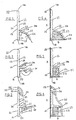
- Figures 1 and 2 detail a section of the sealing member 10 which has a first upper limb 11 for contacting a generally vertical surface A, and a second outer limb 12 for containment of a sealing material 27 on the generally horizontal surface B.
- the outer face 14 of the upper limb 11 has a series of recesses 21 to accommodate the gripping and storage of an adhesive sealant material 23.
- limb 12 Extending outward from the inner face 15 of upper limb 11 is limb 12.
- the upper face 16 of outer limb 12 is directed downward to accommodate the flow of water, while the gap 25 between the outermost boundary line 24 of limb 12 and the horizontal surface B may be reduced through the removal of the lowermost part of limb 11, below the score line 19.
- the sectional thickness of limb 12 is suitably reduced as it extends to the outer boundary 24 to allow movement in the event of surface A moving away from surface B.
- Limb 12 may be flexibly attached to limb 11 at the joint, to accommodate the retro-application of sealing material 27 into the cavity 26.
- a continuous sealing material 27 may be fully or partially applied into the enclosed cavity 26.
- the boundary sides of this cavity 26 provide a form-work/shuttering or enclosure for the sealing material 27, the height and width of which may be dictated by the lower face profile 17 of limb 12, as desired.
- the lower face 17 of limb 12, and/or the inner face part 20 of upper limb 11 are wholly or partially layered with an anti-adherent material 13.
- an anti-adherent material 13 is 100 micron polythene tape (Figure 1) coated on one side with pressure sensitive adhesive that is applied against surfaces as required.
- Another such material is a complementary extrusion 61 and 62 in Figures 22 and 25 respectively.
- the functions of the anti-adherent material 13 or 61 or 62 is to act as a layer or separator or shuttering between all or parts of the seal member 10 and the sealing materials.
- the anti-adherent interface layer between the main seal member 10 and the sealing material 27 is polythene tape 13 which provides a low energy surface to which the sealant material, typically silicone 27, will not strongly adhere when cured.
- the tape may be applied wholly or partially onto the inner surfaces 20 and 17 defining the seal cavity 26.
- Figures 1 and 2 and their respective counterparts Figures 4 and 5 contain basically similar features.
- Figure 3 and it's counterpart Figure 6, detail a third embodiment according to the invention, whereby the sealing member is adapted to engage other seal members as desired.
- the upper part 33 of limb 11 is adapted to retain in angle 32, the upper boundary 36 of a complementary seal member 35 and provide an overhanging sealant reservoir 31, while the outer part 34 of limb 12 is adapted to complementarily engage the clip-on leg detail 37 of said member 35.
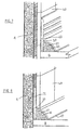
- Figures 7 and 8 represent perspective views of the sealing profile detailed in Figures 1 and 4 whereby in Figure 7 the sealing member 10 is installed over the tiles 40 with a adhesive/sealing material which may be typically though not exclusively silicone or a butyl rubber compound 23.
- a adhesive/sealing material which may be typically though not exclusively silicone or a butyl rubber compound 23.
- Figure 8 details the sealing member 10 with the upper region of the upper limb 11 sandwiched between the vertical surface A and the tiles 40.
- Figures 9 and 12 detail an embodiment whereby the upper most boundary 12a of the second limb 12 (part of which is limb 50), is attached to the first limb 11 to form a cavity 54 which may be filled with a sealant 56 when seal members are joined together.
- the walls forming this cavity 54 may be wholly or partially layered with an anti-adherent material.
- Figures 10 and 13 detail an embodiment whereby upper most boundary 12b of the second limb 12 (part of which is limb 50), is unattached to the first limb 11, but adapted to be engaged between a vertical surface A and wall covering 40 through limb 51, which in itself is adapted through limb 52, to support the said wall covering.
- the upper and lower faces of limb 52 are ribbed to encourage the strong adherence of sealant 57.
- the joint between limb 50 and the attached limbs 51 and 52 is weakened at 58 to enable the easy detachment when the seal member is being installed over the wall covering.
- Figures 11 and 14 detail respectively the seal member described in Figures 10 and 13, but in a surface mounted application, without limbs 51 and 52 attached.
- Figure 15 details a sectional profile of a seal member 10 wherein a second outer limb 63 is introduced to conserve the volume of sealing material 27 used.
- the anti-adherent material in this detail is a polythene tape 13.
- the uppermost surface of the seal cavity 81 is not layered with the polythene tape 13 allowing the sealing material 27 form a bond with this section.
- Figure 18 is a sectional detail of Figure 15 when installed between two surfaces A and B. This is a behind tile installation wherein the tiles 40 are fixed over the upper limb 11.
- Figures 16 details a sectional profile of a seal member 10.
- the anti-adherent material is a polythene tape 13.
- the uppermost surface of the seal cavity 83 is not layered with the polythene tape 13 allowing the sealing material 27 form a bond with this section.
- Figure 19 is a sectional detail of Figure 16 when installed between two surfaces A and B. This is a behind tile installation wherein the tiles 40 are fixed over the upper limb 11.
- Figures 17 details a sectional profile of a seal member 10.
- the anti-adherent material is a polythene tape 13.
- the uppermost surface of the seal cavity 84 is not layered with the polythene tape 13 allowing the sealing material 27 form a bond with this section.
- Figure 20 is a sectional detail of Figure 17 when installed between two surfaces A and B. This is a surface installation wherein the upper limb 11 is fixed over the tiles 40.
- Figures 21 and 22 are sectional details of the main seal member 10 and a complementary anti-adherent extrusion material 61 respectively.
- the outer limb 12 is connected to the lower boundary of the upper limb 11.
- the detached anti-adherent extrusion is the layer and shuttering separating a sealing material 27 from the main seal member 10.
- Figure 23 is a sectional detail of Figures 21 and 22 when assembled and installed between two surfaces A and B.
- the complementary anti-adherent extrusion material 61 is installed prior to the main seal member 10.
- This detail and installation method has the advantages of executing the installation in step by step phases to suit the DIY installer.
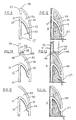
- Figures 24 and 25 are sectional details of the main seal member 10 and a complementary extrusion 62 respectively.
- the extrusion 62 is used; (a) as an anti-adherent and shuttering material for the sealant (b) as a complementary sealing material use with a sealant (c) as a profile adapted to conserve sealant.
- the curved limb 86 of the extrusion 62 is in effect performing as a sealing limb preventing the penetration of liquid into the cavity 85.
- the extrusion 62 is adapted to conserve an un-necessitated volume of sealant material through the provision of lower face limbs 66 and 67 defining a longitudinal channel 64 along its lowermost face, restricting the ingress of sealant into the cavity 85.
- channel 64 also permits the continuous unbroken passage of sealing material 27 from surface B into the cavity 85 of extrusion 62. This is critical when joining two extrusions together or capping an end. Channel 64 also aids the bond between the extrusion 62 and the surface B.
- the lower boundary section 65 may be torn off extrusion 62 along the weakening recess 68.
- the lowermost limbs 66 and 67 defining the channel may be splayed upward to accommodate the passage of excess sealing material 27 into the cavity 85 during installation.
- These lowermost faces 66 and 67 may be fluted or otherwise adapted (not shown) to encourage a good key or bond with the sealing material 27
- main seal members 10 and the complementary anti-adherent/shuttering extrusions (like 61 and 62) are possible.
- Figures 27 and 28 are profile variation similar to those described for Figures 17 and 20.
- Figure 29 details a sectional view of a sealing assembly wherein a first complete seal 70 similar to Figure 16, is combined with a complementary second complete seal 80, and installed over an expansion joint between surfaces C and D.
- the surfaces C and D are in line and parallel, and could reflect either two meeting tiled wall structures or two meeting tiled floor slabs.
- the sealing material 27 is applied into the combined cavity through channel 74 and may later be capped (not shown).
- Figure 30 details a sectional view of a sealing assembly wherein a first complete seal 90 is combined with a second complete seal 91 over an expansion joint between surfaces E and F.
- the surfaces E and F are at right angles, and could reflect either two meeting tiled wall structures or a tiled wall meeting tiled floor slabs.
- the sealing material 27 is applied into the combined cavity through corner channel now capped by extrusion 88.
- the seal members are interconnected by a flexible material 87.
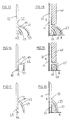
- the first outer limb 115 and a second outer limb 116 are adapted to be easily removed from the main upper 110 through the weakening recesses 117 and 118 respectively.
- the height of the main limb 110 may be reduced through the easy removal of longitudinal sections typically defined by weakening recesses 119 and 120 in the main limb.
- the first 113 and second 114 main limb faces are adapted to retain a sealing/adhesive material through ribs 121 and recesses 122.
- the profile of the upper faces 123 and 124 of the outer limbs 115 and 116 respectively are adapted to throw off liquid.
- the profile of the lower faces 125 and 126 of the outer limbs 115 and 116 respectively are adapted to accommodate and retain a sealing material.
- the lower faces of the outer limbs 115 and 116 are partially layered with anti-adherent membranes 129 and 130 respectively.
- the main upper limb 110 is partially layered with anti-adherent membranes 131 and 132 on the first 113 and second 114 faces respectively.
- the purpose of layering the surfaces 129, 130, 131 and 132 with an anti-adherent material is to form a releasable shuttering for sealing material that may be applied into the cavities 135 and 136 formed between the outer limbs 115 and 116, their respective main upper limb 110 first 113 and second 114 faces and their respective adjacent horizontal surface B, thereby providing continuous up-standing containment cavities 135 and 136 respectively for the applied sealant that will form a boundary wall, bonded to the horizontal surface B, yet wholly or partially independent and/or releasable from the seal member to which initially attached.
- Typical locations for this seal in are in shower bath enclosures, kitchen worktops, wherein the seal is installed longitudinally onto wall over the joint created by the respective ledges and their adjacent walls.
- seal members Measure and cut seal members to the lengths as required (usually three lengths per shower pan or bath), allowing mitre cuts butt joints in corners.
- Taking the first seal member to be installed fix it upside down (mechanically) and slightly overfill the seal cavity with sealant.
- Step 1 Measure and cut anti-adherent extrusions to the lengths as required (usually three lengths per shower pan or bath), allowing mitre cuts in butt joints in corners. Taking the first anti-adherent extrusion to be installed, hold it upside down, slightly overfill the lower face with sealant. Take the sealant filled anti-adherent extrusion and offer it onto it's proposed location, press it down onto the ledge, squeezing out the sealant. Fill the ends solid with sealant. Remove surplus sealant. Continue installing anti-adherent extrusion accordingly, insuring sealant runs solid throughout corners and open ends are capped with sealant.
- Step 2 Measure and cut complementary seal members to the lengths as allowing mitre cuts for butt joints in corners. Lay a bead of sealant above anti-adherent extrusion on the respective wall midway behind the proposed location of the seal member. Take the seal member and offer it against it's proposed location, press it simultaneously against the wall, squeezing out the sealant. Remove surplus sealant. Continue installation accordingly. Apply a bead of sealant over but jointed seal members and rub smooth.
Landscapes
- Health & Medical Sciences (AREA)
- Public Health (AREA)
- Epidemiology (AREA)
- General Health & Medical Sciences (AREA)
- Building Environments (AREA)
- Closures For Containers (AREA)
- Glass Compositions (AREA)
- Burglar Alarm Systems (AREA)
- Moulds, Cores, Or Mandrels (AREA)
- Orthopedics, Nursing, And Contraception (AREA)
Claims (21)
- Dichtungsteil (10) zum unabhängigen Installieren oder als eine Komponente einer Dichtungs-Baueinheit, um eine abgedichtete Verbindung zwischen relativ vertikalen und horizontalen Oberflächen (A,B), die entweder gerade lineare oder Eck-Verbindungen sind, aufrechtzuerhalten, wobei das Dichtungsteil (10) ein erstes im Wesentlichen starres Glied (11) mit einer oberen Begrenzung (14a) und einer unteren Begrenzung (14b) umfasst, zwischen denen sich auf jeder Seite des ersten Gliedes (11) eine innere Fläche (15) und eine äußere Fläche (14) erstreckt, von denen die äußere Fläche (14) zum vollständigen oder teilweisen Fixieren und/oder Abdichten mit der relativ vertikalen Oberfläche (A) eingerichtet ist, und von deren innerer Fläche (15), oberer Begrenzung (14a) oder unterer Begrenzung (14b) sich mindestens ein zweites im Wesentlichen starres Glied (12) erstreckt, das eine innere Begrenzung (24a) und eine äußere Begrenzung (24) aufweist, von denen die innere Begrenzung (24a) an der inneren Fläche (15) und/oder unteren Begrenzung (14b) des ersten Gliedes (11) befestigt ist, und zwischen dessen innerer und äußerer Begrenzung (24a,24) sich auf jeder Seite des zweiten Gliedes (12) eine obere Fläche (16) und eine untere Fläche (17) erstreckt, wobei die untere Fläche (17) vollständig oder teilweise zum Abdichten mit der relativ horizontalen Oberfläche (B) und/oder Anpassen und Halten eines Dichtungsmaterials (27) zwischen der unteren Fläche (17) des zweiten Gliedes und der horizontalen Oberfläche (B) eingerichtet ist, dadurch gekennzeichnet, dass die innere Fläche (15) des ersten Gliedes und/oder die untere Fläche (17) des zweiten Gliedes vollständig oder teilweise mit einem Antihaft-Material (13) beschichtet ist, um eine trennbare Abstützung Für das Dichtungsmaterial (27) in dem Hohlraum (26) zu bilden, der zwischen der inneren Fläche (15) des ersten Gliedes und/oder der unteren Fläche (17) des zweiten Gliedes und der benachbarten horizontalen Oberfläche (B) gebildet ist, wodurch ein kontinuierlicher aufrecht stehender Aufnahmehohlraum für das aufgebrachte Dichtungsmaterial geschaffen ist, das eine Begrenzungswand bildet, die mit der horizontalen Oberfläche verbunden, doch vollständig oder teilweise unabhängig und/oder trennbar von dem Dichtungsteil ist, an dem sie anfänglich befestigt ist.
- Dichtungsteil nach Anspruch 1, worin das Antihaft-Material typischerweise, wenn auch nicht ausschließlich, ein Polythene-Band und/oder ein Antiklebfilm-Spray und/oder ein koextrudiertes Material und/oder ein komplementäres Strangpressprofil ist.
- Dichtungsteil nach einem der vorhergehenden Ansprüche, worin das Dichtungsmaterial typischerweise, aber nicht ausschließlich, unabhängig oder in Kombination, ein Silicon und/oder ein komplementäres Strangpressprofil und/oder ein Butylband und/oder ein Dichtungsmaterial ist.
- Dichtungsteil nach einem der vorhergehenden Ansprüche, worin das Antihaft-Material ein Polythene-Band ist, das auf einer Seite mit Haftkleber überzogen ist, der das Band auf Oberflächen des Dichtungsteiles bindet, auf denen nicht erwünscht ist, dass sich eine Bindung mit dem Dichtungsmaterial oder Teilen davon bildet.
- Dichtungsteil nach einem der vorhergehenden Ansprüche, worin das Antihaft-Material ein Strangpressprofil ist, das zum Schichten gegen das Dichtungsteil eingerichtet ist, um eine Abstützung zwischen dem Dichtungsmaterial und solchen Oberflächen des Dichtungsteiles zu bilden, von denen nicht erwünscht ist, dass sie eine Bindung mit dem Dichtungsmaterial bilden.
- Dichtungsteil nach einem der vorhergehenden Ansprüche, worin ein Strangpressprofil zur gleichzeitigen Anwendung sowohl als ein Teildichtungsmaterial als auch ein Antihaft-Material eingerichtet ist.
- Dichtungsteil nach einem der vorhergehenden Ansprüche, worin ein im Wesentlichen dreiseitiges Strangpressprofil, das sowohl als ein Teildichtungamaterial als auch als ein Antihaft-Material benutzt wird, durch Schaffung eines Längskanales entlang seiner untersten Seite zum Konservieren und/oder Beschränken des Volumens des eingesetzten Dichtungsmaterials eingerichtet ist.
- Dichtungsteil nach einem der vorhergehenden Ansprüche, worin ein Strangpressprofil, das sowohl als ein Teildichtungsmaterial als auch ein Antihaft-Material benutzt wird, durch die Schaffung mindestens eines Abziehstreifens, der an der untersten Fläche befestigt ist, zum einstellbaren Anordnen auf einer Oberfläche eingerichtet ist, wie das Dichtungsteil es erfordern mag.
- Dichtungsteil nach einem der vorhergehenden Ansprüche, worin ein Strangpressprofil, das zur Anwendung sowohl als ein Teildichtungsmaterial als auch als ein Antihaft-Material eingerichtet ist, zur Bildung eines Schlüssels oder einer Bindung zwischen der unteren Fläche und dem Dichtungsmaterial durch die Schaffung von Rippen und/oder Ausnehmungen entlang der äußeren untersten Fläche eingerichtet ist.
- Dichtungsteil nach einem der vorhergehenden Ansprüche, worin das erste und/oder zweite Glied des Dichtungsteiles zum Ablauferlassen von Wasser, das darauf fallen mag, und/oder zum Eingriff mit komplementären Dichtungsteilen eingerichtet ist.
- Dichtungsteil nach einem der vorhergehenden Ansprüche, worin die Außenfläche des ersten Gliedes mehrere Grate und/oder Ausnehmungen und/oder Kontaktpunkte und/oder Löcher aufweist, um an Befestigungsund/oder dichtende Klebstoff-Materialien anzupassen.
- Dichtungsteil nach einem der vorhergehenden Ansprüche, worin die Höhe des ersten Gliedes durch die Schaffung mindestens einer schwächenden Kerblinie, die eine Längsfläche entlang der unteren Begrenzung bildet, die leicht entfernt werden kann, reduziert werden kann, um den Spalt zwischen der äußeren Begrenzung des zweiten Gliedes und einer zweiten Oberfläche zu bestimmen.
- Dichtungsteil nach einem der vorhergehenden Ansprüche, worin das Profil des zweiten Gliedes vollständig und/oder in irgendeiner Reihenkombination konvex und/oder konkav und/oder planar ist.
- Dichtungsteil nach einem der vorhergehenden Ansprüche, worin von dem Übergang, wo das erste Glied das zweite Glied trifft, die Schnittdicke des zweiten Gliedes verringert ist, wie es sich zu seiner äußeren Begrenzung erstreckt, um eine flexible Bewegung gegen die Dichtungsmaterialien zu gestatten.
- Dichtungsteil nach einem der vorhergehenden Ansprüche, worin ein drittes Glied sich vom ersten Glied aus und unterhalb des zweiten Gliedes erstreckt, um das Volumen des eingesetzten Dichtungsmaterials zu konservieren und/oder zu beschränken.
- Dichtungsteil nach einem der vorhergehenden Ansprüche, worin die Verbindung zwischen dem ersten Glied und dem zweiten Glied flexibel zur Anpassung an das Rückaufbringen eines Dichtungsmaterials unter und/oder hinter dem zweiten Gied und/oder an die seitliche Bewegung des Dichtungsmaterials weg vom ersten Glied angepasst ist.
- Dichtungsteil nach einem der vorhergehenden Ansprüche, worin das zweite Glied teilweise eingerichtet ist, sich zurück auf das oder oberhalb des ersten Gliedes zu erstrecken, um ein Dichtungsmittel-Reservoir gegen das erste Glied oder die vertikale Oberfläche zu umfassen und das Dichtungsmittel-Reservoir, das zwischen dem ersten Glied undloder dem zweiten Glied und der horizontalen Oberfläche umfasst ist, zu überlappen.
- Dichtungsteil nach einem der vorhergehenden Ansprüche, worin die obere Dichtungsteil-Begrenzung zum Eingriff mit der vertikalen Oberfläche und einer aufgebrachten Abdeckung und/oder zum Abstützen der aufgebrachten Abdeckung eingerichtet ist.
- Dichtungsteil nach dem vorherigen Anspruch, worin die eingerichtete abstützende obere Begrenzung des Dichtungsteiles wahlweise durch die Schaffung mindestens einer schwächenden Kerblinie unterhalb der Anpassung, die eine Längsfläche bildet, die leicht entfernt werden kann, entfernt werden kann.
- Dichtungsteil nach einem der vorhergehenden Ansprüche, bei dem sich ein drittes Glied von der äußeren Fläche des ersten Gliedes aus erstreckt, wobei die untere Fläche des dritten Gliedes mit einem Antihaft-Material überzogen ist.
- Baueinheit aus zwei Dichtungsteilen, von denen jedes in den vorherigen Ansprüchen beansprucht ist, wobei die beiden Teile miteinander verbunden und/oder komplementär mit Profilen versehen sind, um die Verbindung zwischen den beiden benachbarten Oberflächen abzudichten.
Applications Claiming Priority (9)
| Application Number | Priority Date | Filing Date | Title |
|---|---|---|---|
| GB9819460 | 1998-09-08 | ||
| GB9819460A GB2341427A (en) | 1998-09-08 | 1998-09-08 | Sealing member |
| IES980935 IES980935A2 (en) | 1998-09-08 | 1998-11-12 | Sealing member |
| IE980935 | 1998-11-12 | ||
| GB9824812A GB2343719A (en) | 1998-11-13 | 1998-11-13 | Multi-sized sealing member |
| GB9824812 | 1998-11-13 | ||
| GB9908494 | 1999-04-15 | ||
| GB9908494A GB2348805B (en) | 1999-04-15 | 1999-04-15 | Sealing strip profile |
| PCT/IE1999/000092 WO2000014350A1 (en) | 1998-09-08 | 1999-09-08 | Sealing member |
Publications (2)
| Publication Number | Publication Date |
|---|---|
| EP1112418A1 EP1112418A1 (de) | 2001-07-04 |
| EP1112418B1 true EP1112418B1 (de) | 2003-03-12 |
Family
ID=27451829
Family Applications (1)
| Application Number | Title | Priority Date | Filing Date |
|---|---|---|---|
| EP99941801A Expired - Lifetime EP1112418B1 (de) | 1998-09-08 | 1999-09-08 | Dichtelement |
Country Status (8)
| Country | Link |
|---|---|
| US (1) | US6802161B1 (de) |
| EP (1) | EP1112418B1 (de) |
| AT (1) | ATE234397T1 (de) |
| AU (1) | AU760022B2 (de) |
| CA (1) | CA2343244A1 (de) |
| DE (1) | DE69905914D1 (de) |
| TR (1) | TR200100703T2 (de) |
| WO (1) | WO2000014350A1 (de) |
Families Citing this family (25)
| Publication number | Priority date | Publication date | Assignee | Title |
|---|---|---|---|---|
| GB2364555B (en) * | 2000-07-07 | 2004-02-04 | Anthony Brian Mallows | Method of using a flexible seal |
| US20040181869A1 (en) * | 2001-07-10 | 2004-09-23 | Cowling Russell B | Shower recess and method of construction |
| CA2499827A1 (en) | 2002-10-04 | 2004-04-15 | Gerard Francis Robinson | Sealing system |
| CA2507679A1 (en) * | 2004-05-17 | 2005-11-17 | Tecton Products | Window and door trim system |
| GB2442467B (en) * | 2006-10-02 | 2011-04-27 | Michael Francis Harper | Wall and floor tile panel support system |
| EP2191755A1 (de) * | 2008-11-28 | 2010-06-02 | Supertape B.V. | Dichtungsband und Verfahren zur Herstellung des Dichtungsbands |
| NL2003559C2 (nl) * | 2009-09-28 | 2011-03-29 | Easy Sanitairy Solutions Bv | Afdichting. |
| DE202010000626U1 (de) * | 2010-01-05 | 2010-04-15 | Wedi, Stephan | Kantenabschlussprofil |
| GB2517514B (en) * | 2013-08-21 | 2016-03-16 | Gerard Francis Robinson | Watertight sealing member for use between shower tray or bath and wall |
| USD767168S1 (en) | 2014-06-24 | 2016-09-20 | William Michael Hatch | Panel edge finishing trim |
| USD767169S1 (en) | 2014-06-24 | 2016-09-20 | William Michael Hatch | Outside corner trim |
| US9441381B2 (en) | 2014-06-24 | 2016-09-13 | Stainless Architectural Supply, Llc | Construction element |
| USD754881S1 (en) | 2014-06-24 | 2016-04-26 | William Michael Hatch | Panel divider trim |
| USD762878S1 (en) | 2014-06-24 | 2016-08-02 | William Michael Hatch | Inside corner trim |
| USD754882S1 (en) | 2014-06-24 | 2016-04-26 | William Michael Hatch | Combined panel trim and flashing |
| GB2537810B (en) * | 2015-03-18 | 2020-07-15 | Brian Mallows Anthony | Flexible seal |
| US9980614B2 (en) * | 2016-08-17 | 2018-05-29 | Liberty Hardware Mfg. Corp. | Base member for a shower door assembly |
| CA2998243A1 (en) | 2018-03-16 | 2019-09-16 | Donald J. Fletcher | Corner moulding with break-off base stem portion |
| EP3797197A4 (de) | 2018-05-23 | 2022-06-01 | Sas Ip, Llc | Kronenelemente, sockelleistenelemente, kerbverzahnungen und verwandte verfahren |
| US11072931B2 (en) * | 2018-11-09 | 2021-07-27 | Larry Jones | Cove base with channel for sealant |
| US10655344B1 (en) * | 2018-11-09 | 2020-05-19 | Larry Jones | Cove base with channel for sealant |
| US11746542B2 (en) | 2018-11-09 | 2023-09-05 | Larry Jones | Cove base with channel for sealant |
| IT201900023565A1 (it) * | 2019-12-11 | 2021-06-11 | Progress Profiles Spa | Battiscopa perfezionato |
| US20230061031A1 (en) * | 2021-08-27 | 2023-03-02 | William Michael Hatch | Systems and methods for modular construction elements and interchangeable inserts |
| EP4350100A1 (de) * | 2022-10-07 | 2024-04-10 | Walfred Prossegger | Wandhochzug für bodenbeläge und verfahren zur herstellung eines wandhochzugs |
Family Cites Families (6)
| Publication number | Priority date | Publication date | Assignee | Title |
|---|---|---|---|---|
| GB1236577A (en) * | 1967-11-06 | 1971-06-23 | Patrick William O Brien | Corrugated flexible tubing |
| DE3201083C2 (de) | 1982-01-15 | 1995-09-07 | Gruenzweig & Hartmann Montage | Abdeckvorrichtung, insbesondere für eine Sockelfuge |
| GB8307163D0 (en) | 1983-03-15 | 1983-04-20 | Display Tiling Services Ltd | Sealing strip |
| GB9411173D0 (en) * | 1994-06-03 | 1994-07-27 | Mccomb Barry H | Sanitary ware seal |
| GB2322644A (en) | 1997-02-28 | 1998-09-02 | Gerard Francis Robinson | Seal between a vertical and a horizontal surface, e.g. wall and shower tray |
| WO1998040234A2 (en) | 1997-02-28 | 1998-09-17 | Gerard Francis Robinson | Receptacle seal |
-
1999
- 1999-09-08 TR TR2001/00703T patent/TR200100703T2/xx unknown
- 1999-09-08 DE DE69905914T patent/DE69905914D1/de not_active Expired - Lifetime
- 1999-09-08 EP EP99941801A patent/EP1112418B1/de not_active Expired - Lifetime
- 1999-09-08 WO PCT/IE1999/000092 patent/WO2000014350A1/en not_active Ceased
- 1999-09-08 CA CA002343244A patent/CA2343244A1/en not_active Abandoned
- 1999-09-08 US US09/786,255 patent/US6802161B1/en not_active Expired - Fee Related
- 1999-09-08 AU AU55289/99A patent/AU760022B2/en not_active Ceased
- 1999-09-08 AT AT99941801T patent/ATE234397T1/de not_active IP Right Cessation
Also Published As
| Publication number | Publication date |
|---|---|
| TR200100703T2 (tr) | 2001-06-21 |
| AU760022B2 (en) | 2003-05-08 |
| WO2000014350A1 (en) | 2000-03-16 |
| AU5528999A (en) | 2000-03-27 |
| US6802161B1 (en) | 2004-10-12 |
| CA2343244A1 (en) | 2000-03-16 |
| DE69905914D1 (de) | 2003-04-17 |
| EP1112418A1 (de) | 2001-07-04 |
| ATE234397T1 (de) | 2003-03-15 |
Similar Documents
| Publication | Publication Date | Title |
|---|---|---|
| EP1112418B1 (de) | Dichtelement | |
| CN104641050B (zh) | 用于潮湿区域的防水系统 | |
| EP0122720B1 (de) | Abdichtungselement | |
| GB2289924A (en) | Seal | |
| GB2322644A (en) | Seal between a vertical and a horizontal surface, e.g. wall and shower tray | |
| AU2014310576B2 (en) | Flexible sealing member | |
| GB2341427A (en) | Sealing member | |
| JP2880931B2 (ja) | 断熱サッシ | |
| WO2007149753A2 (en) | Conformable sill membrane | |
| EP1920690A2 (de) | Dichtungssystem | |
| WO1998040234A2 (en) | Receptacle seal | |
| GB2427820A (en) | Non-flexible floor covering adaptor for a shower tray | |
| GB2357963A (en) | Seal for a joint between a tiled wall and a bath or shower tray | |
| WO2023283678A1 (en) | Shower base system | |
| AU2003299188B8 (en) | System for sealing the joint between two contiguous surfaces disposed at an angle to each other | |
| GB2337565A (en) | Sealing member | |
| WO2009050476A2 (en) | Wall panel | |
| GB2348805A (en) | Sealing strip | |
| GB2343719A (en) | Multi-sized sealing member | |
| GB2375708A (en) | Sealing assembly | |
| US20080010917A1 (en) | Flexible Wicking Membrane | |
| JP2531783Y2 (ja) | 床パネル | |
| JP2001348930A (ja) | 防水床パン | |
| AU729845B2 (en) | Waterproofing of wet areas | |
| JP2004156370A (ja) | 目地シール構造及び目地シール方法 |
Legal Events
| Date | Code | Title | Description |
|---|---|---|---|
| PUAI | Public reference made under article 153(3) epc to a published international application that has entered the european phase |
Free format text: ORIGINAL CODE: 0009012 |
|
| 17P | Request for examination filed |
Effective date: 20010406 |
|
| AK | Designated contracting states |
Kind code of ref document: A1 Designated state(s): AT BE CH CY DE DK ES FI FR GB GR IE IT LI LU MC NL PT SE |
|
| AX | Request for extension of the european patent |
Free format text: AL;LT;LV;MK;RO;SI |
|
| GRAG | Despatch of communication of intention to grant |
Free format text: ORIGINAL CODE: EPIDOS AGRA |
|
| 17Q | First examination report despatched |
Effective date: 20020204 |
|
| GRAG | Despatch of communication of intention to grant |
Free format text: ORIGINAL CODE: EPIDOS AGRA |
|
| GRAH | Despatch of communication of intention to grant a patent |
Free format text: ORIGINAL CODE: EPIDOS IGRA |
|
| GRAH | Despatch of communication of intention to grant a patent |
Free format text: ORIGINAL CODE: EPIDOS IGRA |
|
| GRAA | (expected) grant |
Free format text: ORIGINAL CODE: 0009210 |
|
| AK | Designated contracting states |
Designated state(s): AT BE CH CY DE DK ES FI FR GB GR IE IT LI LU MC NL PT SE |
|
| PG25 | Lapsed in a contracting state [announced via postgrant information from national office to epo] |
Ref country code: LI Free format text: LAPSE BECAUSE OF FAILURE TO SUBMIT A TRANSLATION OF THE DESCRIPTION OR TO PAY THE FEE WITHIN THE PRESCRIBED TIME-LIMIT Effective date: 20030312 Ref country code: IT Free format text: LAPSE BECAUSE OF FAILURE TO SUBMIT A TRANSLATION OF THE DESCRIPTION OR TO PAY THE FEE WITHIN THE PRESCRIBED TIME-LIMIT;WARNING: LAPSES OF ITALIAN PATENTS WITH EFFECTIVE DATE BEFORE 2007 MAY HAVE OCCURRED AT ANY TIME BEFORE 2007. THE CORRECT EFFECTIVE DATE MAY BE DIFFERENT FROM THE ONE RECORDED. Effective date: 20030312 Ref country code: GR Free format text: LAPSE BECAUSE OF FAILURE TO SUBMIT A TRANSLATION OF THE DESCRIPTION OR TO PAY THE FEE WITHIN THE PRESCRIBED TIME-LIMIT Effective date: 20030312 Ref country code: FI Free format text: LAPSE BECAUSE OF FAILURE TO SUBMIT A TRANSLATION OF THE DESCRIPTION OR TO PAY THE FEE WITHIN THE PRESCRIBED TIME-LIMIT Effective date: 20030312 Ref country code: CH Free format text: LAPSE BECAUSE OF FAILURE TO SUBMIT A TRANSLATION OF THE DESCRIPTION OR TO PAY THE FEE WITHIN THE PRESCRIBED TIME-LIMIT Effective date: 20030312 Ref country code: AT Free format text: LAPSE BECAUSE OF FAILURE TO SUBMIT A TRANSLATION OF THE DESCRIPTION OR TO PAY THE FEE WITHIN THE PRESCRIBED TIME-LIMIT Effective date: 20030312 |
|
| REG | Reference to a national code |
Ref country code: GB Ref legal event code: FG4D |
|
| REG | Reference to a national code |
Ref country code: CH Ref legal event code: EP |
|
| REG | Reference to a national code |
Ref country code: IE Ref legal event code: FG4D |
|
| REF | Corresponds to: |
Ref document number: 69905914 Country of ref document: DE Date of ref document: 20030417 Kind code of ref document: P |
|
| PG25 | Lapsed in a contracting state [announced via postgrant information from national office to epo] |
Ref country code: SE Free format text: LAPSE BECAUSE OF FAILURE TO SUBMIT A TRANSLATION OF THE DESCRIPTION OR TO PAY THE FEE WITHIN THE PRESCRIBED TIME-LIMIT Effective date: 20030612 Ref country code: DK Free format text: LAPSE BECAUSE OF FAILURE TO SUBMIT A TRANSLATION OF THE DESCRIPTION OR TO PAY THE FEE WITHIN THE PRESCRIBED TIME-LIMIT Effective date: 20030612 |
|
| PG25 | Lapsed in a contracting state [announced via postgrant information from national office to epo] |
Ref country code: DE Free format text: LAPSE BECAUSE OF FAILURE TO SUBMIT A TRANSLATION OF THE DESCRIPTION OR TO PAY THE FEE WITHIN THE PRESCRIBED TIME-LIMIT Effective date: 20030613 |
|
| PG25 | Lapsed in a contracting state [announced via postgrant information from national office to epo] |
Ref country code: PT Free format text: LAPSE BECAUSE OF FAILURE TO SUBMIT A TRANSLATION OF THE DESCRIPTION OR TO PAY THE FEE WITHIN THE PRESCRIBED TIME-LIMIT Effective date: 20030616 |
|
| LTIE | Lt: invalidation of european patent or patent extension |
Effective date: 20030312 |
|
| PG25 | Lapsed in a contracting state [announced via postgrant information from national office to epo] |
Ref country code: LU Free format text: LAPSE BECAUSE OF NON-PAYMENT OF DUE FEES Effective date: 20030908 Ref country code: CY Free format text: LAPSE BECAUSE OF FAILURE TO SUBMIT A TRANSLATION OF THE DESCRIPTION OR TO PAY THE FEE WITHIN THE PRESCRIBED TIME-LIMIT Effective date: 20030908 |
|
| REG | Reference to a national code |
Ref country code: CH Ref legal event code: PL |
|
| PG25 | Lapsed in a contracting state [announced via postgrant information from national office to epo] |
Ref country code: MC Free format text: LAPSE BECAUSE OF NON-PAYMENT OF DUE FEES Effective date: 20030930 Ref country code: ES Free format text: LAPSE BECAUSE OF FAILURE TO SUBMIT A TRANSLATION OF THE DESCRIPTION OR TO PAY THE FEE WITHIN THE PRESCRIBED TIME-LIMIT Effective date: 20030930 |
|
| ET | Fr: translation filed | ||
| PLBE | No opposition filed within time limit |
Free format text: ORIGINAL CODE: 0009261 |
|
| STAA | Information on the status of an ep patent application or granted ep patent |
Free format text: STATUS: NO OPPOSITION FILED WITHIN TIME LIMIT |
|
| 26N | No opposition filed |
Effective date: 20031215 |
|
| PGFP | Annual fee paid to national office [announced via postgrant information from national office to epo] |
Ref country code: NL Payment date: 20070824 Year of fee payment: 9 |
|
| PGFP | Annual fee paid to national office [announced via postgrant information from national office to epo] |
Ref country code: BE Payment date: 20080926 Year of fee payment: 10 |
|
| PGFP | Annual fee paid to national office [announced via postgrant information from national office to epo] |
Ref country code: FR Payment date: 20080926 Year of fee payment: 10 |
|
| PG25 | Lapsed in a contracting state [announced via postgrant information from national office to epo] |
Ref country code: NL Free format text: LAPSE BECAUSE OF NON-PAYMENT OF DUE FEES Effective date: 20090401 |
|
| NLV4 | Nl: lapsed or anulled due to non-payment of the annual fee |
Effective date: 20090401 |
|
| BERE | Be: lapsed |
Owner name: *ROBINSON GERARD FRANCIS Effective date: 20090930 |
|
| REG | Reference to a national code |
Ref country code: FR Ref legal event code: ST Effective date: 20100531 |
|
| PG25 | Lapsed in a contracting state [announced via postgrant information from national office to epo] |
Ref country code: FR Free format text: LAPSE BECAUSE OF NON-PAYMENT OF DUE FEES Effective date: 20090930 |
|
| PG25 | Lapsed in a contracting state [announced via postgrant information from national office to epo] |
Ref country code: BE Free format text: LAPSE BECAUSE OF NON-PAYMENT OF DUE FEES Effective date: 20090930 |
|
| PGFP | Annual fee paid to national office [announced via postgrant information from national office to epo] |
Ref country code: IE Payment date: 20150829 Year of fee payment: 17 |
|
| REG | Reference to a national code |
Ref country code: IE Ref legal event code: MM4A |
|
| PG25 | Lapsed in a contracting state [announced via postgrant information from national office to epo] |
Ref country code: IE Free format text: LAPSE BECAUSE OF NON-PAYMENT OF DUE FEES Effective date: 20160908 |
|
| PGFP | Annual fee paid to national office [announced via postgrant information from national office to epo] |
Ref country code: GB Payment date: 20170811 Year of fee payment: 19 |
|
| GBPC | Gb: european patent ceased through non-payment of renewal fee |
Effective date: 20180908 |
|
| PG25 | Lapsed in a contracting state [announced via postgrant information from national office to epo] |
Ref country code: GB Free format text: LAPSE BECAUSE OF NON-PAYMENT OF DUE FEES Effective date: 20180908 |