EP1111592B1 - Magnetiches Aufnahmegerät - Google Patents
Magnetiches Aufnahmegerät Download PDFInfo
- Publication number
- EP1111592B1 EP1111592B1 EP99125561A EP99125561A EP1111592B1 EP 1111592 B1 EP1111592 B1 EP 1111592B1 EP 99125561 A EP99125561 A EP 99125561A EP 99125561 A EP99125561 A EP 99125561A EP 1111592 B1 EP1111592 B1 EP 1111592B1
- Authority
- EP
- European Patent Office
- Prior art keywords
- head
- gimbal
- magnetic
- drive coil
- recording
- Prior art date
- Legal status (The legal status is an assumption and is not a legal conclusion. Google has not performed a legal analysis and makes no representation as to the accuracy of the status listed.)
- Expired - Lifetime
Links
- 230000005484 gravity Effects 0.000 claims description 8
- 230000002093 peripheral effect Effects 0.000 claims description 2
- 238000013459 approach Methods 0.000 description 1
- 230000000712 assembly Effects 0.000 description 1
- 238000000429 assembly Methods 0.000 description 1
- 239000000919 ceramic Substances 0.000 description 1
- 230000007547 defect Effects 0.000 description 1
- 230000000694 effects Effects 0.000 description 1
- 238000005187 foaming Methods 0.000 description 1
- 239000000463 material Substances 0.000 description 1
- 238000000034 method Methods 0.000 description 1
Images

Classifications
-
- G—PHYSICS
- G11—INFORMATION STORAGE
- G11B—INFORMATION STORAGE BASED ON RELATIVE MOVEMENT BETWEEN RECORD CARRIER AND TRANSDUCER
- G11B5/00—Recording by magnetisation or demagnetisation of a record carrier; Reproducing by magnetic means; Record carriers therefor
- G11B5/48—Disposition or mounting of heads or head supports relative to record carriers ; arrangements of heads, e.g. for scanning the record carrier to increase the relative speed
- G11B5/58—Disposition or mounting of heads or head supports relative to record carriers ; arrangements of heads, e.g. for scanning the record carrier to increase the relative speed with provision for moving the head for the purpose of maintaining alignment of the head relative to the record carrier during transducing operation, e.g. to compensate for surface irregularities of the latter or for track following
- G11B5/60—Fluid-dynamic spacing of heads from record-carriers
- G11B5/6005—Specially adapted for spacing from a rotating disc using a fluid cushion
-
- G—PHYSICS
- G11—INFORMATION STORAGE
- G11B—INFORMATION STORAGE BASED ON RELATIVE MOVEMENT BETWEEN RECORD CARRIER AND TRANSDUCER
- G11B5/00—Recording by magnetisation or demagnetisation of a record carrier; Reproducing by magnetic means; Record carriers therefor
- G11B5/48—Disposition or mounting of heads or head supports relative to record carriers ; arrangements of heads, e.g. for scanning the record carrier to increase the relative speed
- G11B5/488—Disposition of heads
- G11B5/4886—Disposition of heads relative to rotating disc
-
- G—PHYSICS
- G11—INFORMATION STORAGE
- G11B—INFORMATION STORAGE BASED ON RELATIVE MOVEMENT BETWEEN RECORD CARRIER AND TRANSDUCER
- G11B5/00—Recording by magnetisation or demagnetisation of a record carrier; Reproducing by magnetic means; Record carriers therefor
- G11B5/012—Recording on, or reproducing or erasing from, magnetic disks
Definitions
- the present invention relates to a magnetic recording device for a magnetic disk wherein the structure of a magnetic head assembly mounted on a gimbal is improved and the follow-up performance of a head is improved.
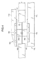
- Fig. 4 is a partial side view showing an example of upper and lower magnetic heads 10U and 10L used in a double sides recorded type floppy disk drive (FDD).
- One magnetic head 10 is a part of a carriage 11 which is a carrier and supports the periphery of a gimbal 12.
- the center of the gimbal 12 is elastically coupled to the periphery.
- a magnetic head assembly 20 is elastically supported by the above center of the gimbal 12.
- the end of a pivot 13 is in contact with a reverse surface to the surface on which the magnetic head assembly 20 is mounted of the center of the gimbal 12.
- the pivot 13 is used for preventing regression in the direction of the carriage 11 without preventing the three-dimensional movement of the center of the gimbal 12.
- a reference number 40 denotes a floppy disk (FD) on the double sides of which data is recorded and 41 denotes a jacket with the thickness of T for housing FD 40.
- FD floppy disk
- the magnetic head assembly 20 is composed of a slider 21 having a surface slid on FD 40, a head core 22 fixed to the slider 21 and a driving coil 23 into which the leg portion of the head core 22 is inserted.
- a coil for recording and reproducing and a coil for erasing are included in the driving coil 23 .
- a reference number 22 denotes a head core for low density recording
- 23 denotes its driving coil
- 24 denotes a head core for high density recording
- 27 denotes a driving coil wound on the head core for high density recording 24.
- the driving coil 27 is embedded in a concave portion 21A formed in the slider 21.
- the material of the slider 21 is generally ceramic.
- a gap for recording/reproduction and a gap for erasing are formed on each surface of the head cores 22 and 24.
- a back bar 28 is attached to the open end of the head core 22 for low density recording, both are fixed by a back bar clip 29 and forms a closed magnetic circuit.
- the driving coil 23 is mounted on the side of the upper surface of the gimbal 12 together with the slider 21. Therefore, the slider 21 is mounted on a head base 60 and is supported in a position of height H apart from the surface of the gimbal 12.
- a wire 25 pulled out from the driving coil 27 and a wire 26 pulled out from the driving coil 23 are connected to a flexible printed circuit (FPC) (not shown) mounted on the carriage 11 through an opening formed in the gimbal 12.
- FPC flexible printed circuit
- the purpose of supporting the magnetic head assembly 20 by the gimbal 12 is to make the flat sliding surface of the slider 21 to follow the recorded face of FD because the recorded face of FD is not completely flat but has waviness.
- the center of gravity is located apart from the end of the pivot 13.
- the head touch becomes worse when the runout of FD 40 or the like occurs.
- the variation of output is increased and a problem that a servo characteristic is deteriorated occurs.
- the present invention is provided to solve the above problems. It is therefore an object of the present invention is to provide a magnetic recording device wherein the follow-up performance of a magnetic head for a magnetic disk is improved by improving the structure of a magnetic head assembly mounted on a gimbal.
- the magnetic recording head may further comprises:
- a back bar for forming a closed magnetic circuit is provided on the end portion of the first core on which the first drive coil is provided so as to face a side of that the second head core is provided.
- the gimbal includes a hole through which an electric wire drawn from the second drive coil is passed.
- the abutting point of the pivot member situates in the vicinity of a center of gravity of the recording head assembly.
- a magnetic recording device used for a magnetic disk, wherein the above recording head is provided on each side of the magnetic disk.
- the magnetic recording device wherein the follow-up performance of the magnetic head for the magnetic disk is improved can be realized.
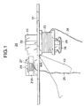
- Fig. 1 is a side view showing the main part of an embodiment of a magnetic recording device according to the present invention.
- a reference number 12 denotes a gimbal for elastically supporting a magnetic head assembly 20.
- a slider 20 of the magnetic head assembly 20 is mounted on one surface of the gimbal 12, while a driving coil 23 wound on a head core 22 fixed to the slider 21 is mounted on the other side of the gimbal 12.
- the head base (60 in Fig. 5) that supports the slider 21 is not required by the above change of the structure and the magnetic head assembly 20 is lightened by the quantity.
- the above lightening is convenient to improve the follow-up performance of a head.
- the center of gravity of the magnetic head assembly 20 approaches the end of a pivot 13. According to suitable design, the above center of gravity can be approximately equalized to a position in which the end of the pivot 13 is touched.
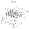
- Fig. 2 is a perspective view showing the whole magnetic recording device shown in Fig. 1.
- the magnetic head assembly 20 is supported by the center 12C of the gimbal 12.
- the periphery 12A of the gimbal 12 is fixed to the head of a pair of walls 11A stood from the side of the carriage 11.
- a shield ring 30 for magnetically shielding the periphery of the driving coil 23 of the magnetic head assembly 20 is fixed to a flat part 11 B of the carriage 11 in a state in which the shield ring is structurally separated from the magnetic head assembly 20 and the gimbal 12.
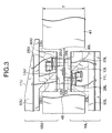
- Fig. 3 is a side view in a case where the magnetic recording device shown in Fig. 1 is applied to a recording device for recording on double sides.
- a magnetic head on the upper side 10U and a magnetic head on the lower side 10L are opposed in a state in which they are respectively touched to both sides of FD 40 of a type for recording on double sides.
- a reference number 41 denotes a jacket of thickness T housing FD 40.
- U or L is added to each part composing the upper and lower magnetic heads 10U and 10L after each reference number for distinction.
- Upper and lower carriages 11U and 11L house each flexible printed circuit (FPC) 50U, 50L and wires 25U and 25L respectively from the driving coils for low density recording 23U and 23L and wires 26U and 26L respectively from the coils for high density recording not shown are respectively connected to the flexible printed circuits.
- the magnetic head assemblies 20U and 20L are respectively mounted on the gimbals 12U and 12L.
- the gimbals 12U and 12L are respectively fixed to the carriages 11U and 11L or are respectively fixed to the shield rings 30U and 30L.
- the respective backs of the gimbals 12U and 12L are supported by pivots 13U and 13L respectively protruded from the carriages 11U and 11L.
- each pivot 13 of the upper and lower heads is located in the thickness T of the jacket 41 and the center of gravity of the head can be coincident with the end of the pivot 13, the weight of the head can be reduced and the moment of inertia around the pivot 13 can be greatly reduced. Therefore, even if large waviness is caused on FD 40, the head can momentarily follow FD and a servo characteristic can be stabilized.
- the wire of the coil for high density recording passes the opening of the gimbal 12, there is an advantage that manhour is reduced.
- the height of the head can be reduced and the head has structure smaller than a window of the FD jacket, a risk that the wire is touched to the jacket is removed.
- the magnetic recording device can be manufactured at a low price.
Landscapes
- Adjustment Of The Magnetic Head Position Track Following On Tapes (AREA)
Claims (6)
- Magnetaufzeichnungskopf, der für eine Magnetplatte eingesetzt wird und umfasst:eine Aufzeichnungskopfbaugruppe (20), die enthält:ein Gleiterelement (20) mit einer Fläche, die gleitend auf einer Fläche der Aufzeichnungsplatte (40) zu bewegen ist;ein Kopfkemelement (22, 24), das an dem Gleiterelement (20) so befestigt ist, dass ein Endabschnitt desselben zusammen mit der Gleitfläche des Gleiters (20) eine Aufzeichnungsfläche bildet; undein Antriebsspulenelement (23, 27), das an dem anderen Endabschnitt des Kopfkernelementes (22, 24) vorhanden ist;einen plattenartiger Kardanbügel (12), der die Aufzeichnungskopfbaugruppe (20) in einem Mittelabschnitt derselben so trägt, dass das Gleiterelement (20) auf der Seite einer ersten Außenfläche desselben angeordnet ist und das Antriebsspulenelement (23, 27) an der Seite einer zweiten Außenfläche desselben angeordnet ist; undein Schwenkelement (13), das an dem Mittelabschnitt der zweiten Außenfläche des Kardanbügels (12) anliegt, wobei das Kopfkernelement (22, 24) einen ersten Kopfkern (22) enthält, der für ein Aufzeichnen mit niedriger Dichte eingesetzt wird, und wobei das Spulenelement (23, 27) eine erste Antriebsspule (23) enthält, die an einem Endabschnitt des ersten Kopfkerns (22) vorhanden ist, dadurch gekennzeichnet, dass das Kopfkernelement (23, 24) des Weiteren einen zweiten Kopfkern (24) enthält, der für ein Aufzeichnen mit hoher Dichte eingesetzt wird, und das Spulenelement (23, 27) eine zweite Antriebsspule (27) enthält, die an einem Endabschnitt des zweiten Kopfkerns (24) vorhanden ist, unddie erste Antriebspule (23) sowie die zweite Antriebsspule (27) an einander gegenüberliegenden Seiten des plattenartigen Kardanbügels (12) vorhanden sind.
- Magnetaufzeichnungskopf nach Anspruch 1, der des Weiteren umfasst:einen Schlitten, der einen Umfangsabschnitt (12A) des Kardanbügels (12) trägt;und einen Abschirmring (30), der das Antriebsspulenelement (23, 27) umgibt, um es magnetisch abzuschirmen.
- Magnetaufzeichnungskopf nach Anspruch 1, wobei ein Gegenstab (28) zum Ausbilden eines geschlossenen Magnetkreises an dem Endabschnitt des ersten Kerns (22), an dem die erste Antriebsspule (23) vorhanden ist, so vorhanden ist, dass er einer Seite zugewandt ist, an der der zweite Kopfkern (24) vorhanden ist.
- Magnetaufzeichnungskopf nach Anspruch 1, wobei der Kardanbügel (12) ein Loch enthält, durch das ein elektrischer Draht (25), der aus der zweiten Antriebsspule (27) gezogen wird, hindurchgeführt wird.
- Magnetaufzeichnungskopf nach einem der Ansprüche 1 bis 4, wobei sich der Anschlagpunkt (WP) des Schwenkelementes (13) in der Nähe eines Schwerpunktes der Aufzeichnungskopfbaugruppe befindet.
- Magnetaufzeichnungsvorrichtung, die für eine Magnetplatte eingesetzt wird, wobei der Aufzeichnungskopf nach einem der Ansprüche 1 bis 5 an jeder Seite der Magnetplatte (40) vorhanden ist.
Priority Applications (3)
| Application Number | Priority Date | Filing Date | Title |
|---|---|---|---|
| JP10178248A JP2000011516A (ja) | 1998-06-25 | 1998-06-25 | 磁気記録装置 |
| EP99125561A EP1111592B1 (de) | 1998-06-25 | 1999-12-21 | Magnetiches Aufnahmegerät |
| DE69909491T DE69909491D1 (de) | 1999-12-21 | 1999-12-21 | Magnetiches Aufnahmegerät |
Applications Claiming Priority (2)
| Application Number | Priority Date | Filing Date | Title |
|---|---|---|---|
| JP10178248A JP2000011516A (ja) | 1998-06-25 | 1998-06-25 | 磁気記録装置 |
| EP99125561A EP1111592B1 (de) | 1998-06-25 | 1999-12-21 | Magnetiches Aufnahmegerät |
Publications (2)
| Publication Number | Publication Date |
|---|---|
| EP1111592A1 EP1111592A1 (de) | 2001-06-27 |
| EP1111592B1 true EP1111592B1 (de) | 2003-07-09 |
Family
ID=26153207
Family Applications (1)
| Application Number | Title | Priority Date | Filing Date |
|---|---|---|---|
| EP99125561A Expired - Lifetime EP1111592B1 (de) | 1998-06-25 | 1999-12-21 | Magnetiches Aufnahmegerät |
Country Status (2)
| Country | Link |
|---|---|
| EP (1) | EP1111592B1 (de) |
| JP (1) | JP2000011516A (de) |
Family Cites Families (5)
| Publication number | Priority date | Publication date | Assignee | Title |
|---|---|---|---|---|
| JPS61287087A (ja) * | 1985-06-14 | 1986-12-17 | Hitachi Ltd | フレキシブルデイスクドライブの磁気ヘツド支持機構 |
| JPH02306418A (ja) * | 1989-05-19 | 1990-12-19 | Tdk Corp | 磁気ヘッドのジンバル板およびフロッピィディスク用磁気ヘッド装置 |
| JPH0467372A (ja) * | 1990-07-03 | 1992-03-03 | Nec Corp | 磁気ヘッドスライダ支持機構 |
| JPH04149816A (ja) * | 1990-10-15 | 1992-05-22 | Teac Corp | 磁気ヘッド |
| JPH09231537A (ja) * | 1996-02-28 | 1997-09-05 | Mitsumi Electric Co Ltd | フロッピーディスク用磁気ヘッド |
-
1998
- 1998-06-25 JP JP10178248A patent/JP2000011516A/ja active Pending
-
1999
- 1999-12-21 EP EP99125561A patent/EP1111592B1/de not_active Expired - Lifetime
Also Published As
| Publication number | Publication date |
|---|---|
| JP2000011516A (ja) | 2000-01-14 |
| EP1111592A1 (de) | 2001-06-27 |
Similar Documents
| Publication | Publication Date | Title |
|---|---|---|
| EP0921525B1 (de) | Plattenlaufwerk | |
| US5666239A (en) | Laminated base deck for a disc drive | |
| US7525758B2 (en) | Disk drive with non-magnetic cover and base plated with conductively connected magnetic shielding layers | |
| US4811140A (en) | Magnetic data transfer apparatus having improved transducer coil arrangement | |
| EP0439943A2 (de) | Aufzeichnungskopfkernjoch mit ganzer-Länge-Kern-Träger | |
| JP3375259B2 (ja) | 磁気ディスク装置 | |
| US6847507B2 (en) | Construction method and design for a magnetic head actuator mechanism | |
| EP1111592B1 (de) | Magnetiches Aufnahmegerät | |
| US5260846A (en) | Compact hard disk assembly having a head carriage positioning arts located within the outer circumference of a hard disk | |
| US5841606A (en) | Magnetic recording/reproducing device with magnetic shield between voice coil motor and flexible cable | |
| US6286759B1 (en) | Multi-magnetic head for a card-shaped recording medium | |
| US7663836B2 (en) | Disk drive base/cover plate with push pin hole having enlarged portion | |
| EP1113424A1 (de) | Magnetische Aufzeichnungsvorrichtung | |
| US20030214758A1 (en) | Flex clamp in a disc drive for retaining a voice coil motor magnetic pole on a base | |
| JPS6139984A (ja) | フロツピ−デイスク駆動装置 | |
| US20060221494A1 (en) | Disk device | |
| JP2610288B2 (ja) | 磁気ヘッド | |
| CN100367358C (zh) | 盘装置 | |
| KR20000020323A (ko) | 하부 요크를 갖는 하드디스크 드라이브의 베이스 | |
| JP2885106B2 (ja) | 磁気ヘッド | |
| KR0120920Y1 (ko) | 하드디스크 드라이브의 액츄에이터 장치 | |
| JP2575962Y2 (ja) | 磁気ヘッド構造 | |
| JPH0636215A (ja) | 磁気ヘッド | |
| JPH11288545A (ja) | 両面記録用磁気ヘッド | |
| JPH11288546A (ja) | 両面記録用磁気ヘッド |
Legal Events
| Date | Code | Title | Description |
|---|---|---|---|
| PUAI | Public reference made under article 153(3) epc to a published international application that has entered the european phase |
Free format text: ORIGINAL CODE: 0009012 |
|
| 17P | Request for examination filed |
Effective date: 20000613 |
|
| AK | Designated contracting states |
Kind code of ref document: A1 Designated state(s): DE FR GB IT NL |
|
| AX | Request for extension of the european patent |
Free format text: AL;LT;LV;MK;RO;SI |
|
| AKX | Designation fees paid |
Free format text: DE FR GB IT NL |
|
| GRAH | Despatch of communication of intention to grant a patent |
Free format text: ORIGINAL CODE: EPIDOS IGRA |
|
| GRAH | Despatch of communication of intention to grant a patent |
Free format text: ORIGINAL CODE: EPIDOS IGRA |
|
| GRAA | (expected) grant |
Free format text: ORIGINAL CODE: 0009210 |
|
| AK | Designated contracting states |
Designated state(s): DE FR GB IT NL |
|
| PG25 | Lapsed in a contracting state [announced via postgrant information from national office to epo] |
Ref country code: NL Free format text: LAPSE BECAUSE OF FAILURE TO SUBMIT A TRANSLATION OF THE DESCRIPTION OR TO PAY THE FEE WITHIN THE PRESCRIBED TIME-LIMIT Effective date: 20030709 Ref country code: IT Free format text: LAPSE BECAUSE OF FAILURE TO SUBMIT A TRANSLATION OF THE DESCRIPTION OR TO PAY THE FEE WITHIN THE PRESCRIBED TIME-LIMIT;WARNING: LAPSES OF ITALIAN PATENTS WITH EFFECTIVE DATE BEFORE 2007 MAY HAVE OCCURRED AT ANY TIME BEFORE 2007. THE CORRECT EFFECTIVE DATE MAY BE DIFFERENT FROM THE ONE RECORDED. Effective date: 20030709 |
|
| REG | Reference to a national code |
Ref country code: GB Ref legal event code: FG4D |
|
| REF | Corresponds to: |
Ref document number: 69909491 Country of ref document: DE Date of ref document: 20030814 Kind code of ref document: P |
|
| PG25 | Lapsed in a contracting state [announced via postgrant information from national office to epo] |
Ref country code: DE Free format text: LAPSE BECAUSE OF FAILURE TO SUBMIT A TRANSLATION OF THE DESCRIPTION OR TO PAY THE FEE WITHIN THE PRESCRIBED TIME-LIMIT Effective date: 20031010 |
|
| NLV1 | Nl: lapsed or annulled due to failure to fulfill the requirements of art. 29p and 29m of the patents act | ||
| PG25 | Lapsed in a contracting state [announced via postgrant information from national office to epo] |
Ref country code: GB Free format text: LAPSE BECAUSE OF NON-PAYMENT OF DUE FEES Effective date: 20031221 |
|
| PGFP | Annual fee paid to national office [announced via postgrant information from national office to epo] |
Ref country code: FR Payment date: 20031223 Year of fee payment: 5 |
|
| ET | Fr: translation filed | ||
| PLBE | No opposition filed within time limit |
Free format text: ORIGINAL CODE: 0009261 |
|
| STAA | Information on the status of an ep patent application or granted ep patent |
Free format text: STATUS: NO OPPOSITION FILED WITHIN TIME LIMIT |
|
| 26N | No opposition filed |
Effective date: 20040414 |
|
| GBPC | Gb: european patent ceased through non-payment of renewal fee |
Effective date: 20031221 |
|
| PG25 | Lapsed in a contracting state [announced via postgrant information from national office to epo] |
Ref country code: FR Free format text: LAPSE BECAUSE OF NON-PAYMENT OF DUE FEES Effective date: 20050831 |
|
| REG | Reference to a national code |
Ref country code: FR Ref legal event code: ST |