EP1111240B1 - Electric compressor - Google Patents
Electric compressor Download PDFInfo
- Publication number
- EP1111240B1 EP1111240B1 EP00942404A EP00942404A EP1111240B1 EP 1111240 B1 EP1111240 B1 EP 1111240B1 EP 00942404 A EP00942404 A EP 00942404A EP 00942404 A EP00942404 A EP 00942404A EP 1111240 B1 EP1111240 B1 EP 1111240B1
- Authority
- EP
- European Patent Office
- Prior art keywords
- section
- rotor
- bearing
- motor
- compressor
- Prior art date
- Legal status (The legal status is an assumption and is not a legal conclusion. Google has not performed a legal analysis and makes no representation as to the accuracy of the status listed.)
- Expired - Lifetime
Links
- XEEYBQQBJWHFJM-UHFFFAOYSA-N Iron Chemical group [Fe] XEEYBQQBJWHFJM-UHFFFAOYSA-N 0.000 claims description 12
- 239000000696 magnetic material Substances 0.000 claims description 11
- 239000000463 material Substances 0.000 claims description 7
- 230000004907 flux Effects 0.000 description 11
- XAGFODPZIPBFFR-UHFFFAOYSA-N aluminium Chemical compound [Al] XAGFODPZIPBFFR-UHFFFAOYSA-N 0.000 description 7
- 229910052782 aluminium Inorganic materials 0.000 description 7
- 238000004512 die casting Methods 0.000 description 7
- 239000004020 conductor Substances 0.000 description 6
- 229910000831 Steel Inorganic materials 0.000 description 4
- 230000004888 barrier function Effects 0.000 description 4
- 230000006698 induction Effects 0.000 description 4
- 229910052742 iron Inorganic materials 0.000 description 4
- 239000007858 starting material Substances 0.000 description 4
- 239000010959 steel Substances 0.000 description 4
- 230000001360 synchronised effect Effects 0.000 description 4
- 238000005266 casting Methods 0.000 description 3
- 239000000314 lubricant Substances 0.000 description 3
- 238000005461 lubrication Methods 0.000 description 3
- 239000000126 substance Substances 0.000 description 3
- 230000008901 benefit Effects 0.000 description 2
- 238000007599 discharging Methods 0.000 description 2
- 230000006872 improvement Effects 0.000 description 2
- QJVKUMXDEUEQLH-UHFFFAOYSA-N [B].[Fe].[Nd] Chemical compound [B].[Fe].[Nd] QJVKUMXDEUEQLH-UHFFFAOYSA-N 0.000 description 1
- 239000000919 ceramic Substances 0.000 description 1
- 239000002826 coolant Substances 0.000 description 1
- -1 copper-system Substances 0.000 description 1
- 230000008878 coupling Effects 0.000 description 1
- 238000010168 coupling process Methods 0.000 description 1
- 238000005859 coupling reaction Methods 0.000 description 1
- 230000008014 freezing Effects 0.000 description 1
- 238000007710 freezing Methods 0.000 description 1
- 230000037431 insertion Effects 0.000 description 1
- 238000003780 insertion Methods 0.000 description 1
- 229910001172 neodymium magnet Inorganic materials 0.000 description 1
- 230000001681 protective effect Effects 0.000 description 1
- 229910052761 rare earth metal Inorganic materials 0.000 description 1
- 150000002910 rare earth metals Chemical class 0.000 description 1
- 230000001105 regulatory effect Effects 0.000 description 1
- 229920006395 saturated elastomer Polymers 0.000 description 1
- 238000004804 winding Methods 0.000 description 1
Images



Classifications
-
- F—MECHANICAL ENGINEERING; LIGHTING; HEATING; WEAPONS; BLASTING
- F04—POSITIVE - DISPLACEMENT MACHINES FOR LIQUIDS; PUMPS FOR LIQUIDS OR ELASTIC FLUIDS
- F04B—POSITIVE-DISPLACEMENT MACHINES FOR LIQUIDS; PUMPS
- F04B39/00—Component parts, details, or accessories, of pumps or pumping systems specially adapted for elastic fluids, not otherwise provided for in, or of interest apart from, groups F04B25/00 - F04B37/00
-
- F—MECHANICAL ENGINEERING; LIGHTING; HEATING; WEAPONS; BLASTING
- F04—POSITIVE - DISPLACEMENT MACHINES FOR LIQUIDS; PUMPS FOR LIQUIDS OR ELASTIC FLUIDS
- F04B—POSITIVE-DISPLACEMENT MACHINES FOR LIQUIDS; PUMPS
- F04B35/00—Piston pumps specially adapted for elastic fluids and characterised by the driving means to their working members, or by combination with, or adaptation to, specific driving engines or motors, not otherwise provided for
- F04B35/04—Piston pumps specially adapted for elastic fluids and characterised by the driving means to their working members, or by combination with, or adaptation to, specific driving engines or motors, not otherwise provided for the means being electric
-
- F—MECHANICAL ENGINEERING; LIGHTING; HEATING; WEAPONS; BLASTING
- F04—POSITIVE - DISPLACEMENT MACHINES FOR LIQUIDS; PUMPS FOR LIQUIDS OR ELASTIC FLUIDS
- F04B—POSITIVE-DISPLACEMENT MACHINES FOR LIQUIDS; PUMPS
- F04B39/00—Component parts, details, or accessories, of pumps or pumping systems specially adapted for elastic fluids, not otherwise provided for in, or of interest apart from, groups F04B25/00 - F04B37/00
- F04B39/0094—Component parts, details, or accessories, of pumps or pumping systems specially adapted for elastic fluids, not otherwise provided for in, or of interest apart from, groups F04B25/00 - F04B37/00 crankshaft
-
- F—MECHANICAL ENGINEERING; LIGHTING; HEATING; WEAPONS; BLASTING
- F04—POSITIVE - DISPLACEMENT MACHINES FOR LIQUIDS; PUMPS FOR LIQUIDS OR ELASTIC FLUIDS
- F04B—POSITIVE-DISPLACEMENT MACHINES FOR LIQUIDS; PUMPS
- F04B39/00—Component parts, details, or accessories, of pumps or pumping systems specially adapted for elastic fluids, not otherwise provided for in, or of interest apart from, groups F04B25/00 - F04B37/00
- F04B39/12—Casings; Cylinders; Cylinder heads; Fluid connections
- F04B39/122—Cylinder block
-
- H—ELECTRICITY
- H02—GENERATION; CONVERSION OR DISTRIBUTION OF ELECTRIC POWER
- H02K—DYNAMO-ELECTRIC MACHINES
- H02K7/00—Arrangements for handling mechanical energy structurally associated with dynamo-electric machines, e.g. structural association with mechanical driving motors or auxiliary dynamo-electric machines
- H02K7/08—Structural association with bearings
- H02K7/085—Structural association with bearings radially supporting the rotary shaft at only one end of the rotor
-
- Y—GENERAL TAGGING OF NEW TECHNOLOGICAL DEVELOPMENTS; GENERAL TAGGING OF CROSS-SECTIONAL TECHNOLOGIES SPANNING OVER SEVERAL SECTIONS OF THE IPC; TECHNICAL SUBJECTS COVERED BY FORMER USPC CROSS-REFERENCE ART COLLECTIONS [XRACs] AND DIGESTS
- Y10—TECHNICAL SUBJECTS COVERED BY FORMER USPC
- Y10S—TECHNICAL SUBJECTS COVERED BY FORMER USPC CROSS-REFERENCE ART COLLECTIONS [XRACs] AND DIGESTS
- Y10S417/00—Pumps
- Y10S417/902—Hermetically sealed motor pump unit
Definitions
- the present invention relates to an electric compressor used in a freezer, refrigerator, or air-conditioner. More particularly it relates to a highly efficient electric compressor in which loss torque and iron loss due to magnetic attraction are reduced. The magnetic attraction is produced at a bearing in a compressing section jointed to a motor section of the compressor.
- the compressor comprises hermetic container 1, compressing section 2 disposed at lower part of the container, and motor section 3 disposed above the compressing section.
- Shaft 4 mounted to rotor 14 of motor section 3 has crank 4a on its tip.
- Cylinder block 5 formed of a casting made of iron system material comprises bearing 6, in which shaft 4 is inserted, and cylinder 7 formed at right angles with bearing 6.
- Piston 9 is linked to crank 4a via connecting rod 8.
- motor section 3 When motor section 3 is driven, rotating movement of shaft 4 is converted to reciprocal movement by crank 4a, and delivered to piston 9 via rod 8, so that piston 9 slides with respect to inner wall of cylinder 7.
- Compressing chamber 10 is formed by cylinder 7 and piston 9.
- Oil pipe 11 is mounted to a tip of crank 4a, and lubricant 12 pooled at the bottom of hermetic container 1 is lubricated to compressing section 2 and shaft 4 through oil pipe 11, so that respective sliding sections move smoothly.
- Motor 3 is a two-pole induction motor comprising the following elements: (a) stator 13 formed of winding-wound-iron-core made of laminated magnetic sheets, and (b) rotor 14 formed of rotor iron core 15 with a secondary conductor, the rotor iron core being made of laminated magnetic sheets.
- Bored section 16 is provided at the end of rotor-iron-core 15 on the side of compressing section 2, and bearing 6 extends inside bored section 16.
- piston 9 When rotor 14 spins, piston 9 performs reciprocal movement via connecting rod 8 linked to crank 4a of shaft 4, so that piston 9 compresses coolant gas in compressing chamber 10.
- the compressed gas is discharged through a discharging pipe (not shown) to a system such as a freezer, refrigerator, or air-conditioner.
- oil pipe 11 mounted to lower end of shaft 4 rotates and pumps up lubricant 12 for lubrication.
- a self-starting-synchronous-type two-pole motor using permanent magnets draws attention as another measures for increasing the efficiency of the motor. Because the permanent magnets are buried in the rotor, thereby eliminating the exciting power.
- Rotor 17 of the synchronous motor comprises iron core 18 made of laminated magnetic steel sheets and shaft hole 19 for receiving shaft 4 to fit into core 18.
- Bored section 20 is provided at the end of core 18 in an axial direction. It is not shown in the drawings, but a part of bearing 6 of a cylinder block 5 extends inside bored section 20.
- Two pieces of plate-type permanent magnet 21 butt each other and form angle alpha to shape in a hill. Two pairs of these magnets 21 are inserted into rotor 17. A first pair of two magnets are placed such that S pole faces outside the rotor and N pole faces inside the rotor. A second pair of two magnets are placed such that N pole faces outside the rotor and S pole faces inside the rotor. Thus the first pair forms a rotor pole and the second pair forms another pole, so that entire rotor 17 has two poles.
- the width of magnet 21 is referred to as "P".
- a starter cage-shaped conductor is unitarily formed by aluminum diecasting comprising numbers of conductive bars 22 provided to core 18 and shorting grommets 23 covering both ends of core 18 in an axial direction.
- Both end-faces of core 18 in the axial direction have protective terminal plates 24 made of non-magnetic material for securing magnets 21 from coming off.
- Barriers 25, for preventing magnetic flux between the permanent magnets from shorting, are provided to core 18. Barriers 25 are unitarily formed with the starter cage-shaped conductor by the aluminum diecasting.
- the flow of magnetic flux from magnet 21 is schematically described with reference to Fig. 7 using the arrow marked lines.
- the magnetic flux from N poles of two magnets 21 placed at upper side of Fig. 7 travels mainly through the center section of core 18 and is attracted to S poles of two magnets 21 placed at lower side of Fig. 7 .
- the magnetic density through core section 18a around the outer rim 20a of bored section becomes substantially high.
- self-starting-synchronous type motor using permanent magnets can be used instead of the conventional induction motor.
- bearing 6 made of iron-system material exists inside bored section 20
- magnetic attraction works between the inner wall of bored section excited and the outer wall of bearing 6.
- the magnetic attraction produces loss torque which lowers the torque produced by the motor, and yet, magnetic flux of magnet 21 travels to bearing 6 and produces eddy-current-loss.
- the motor needs another power to compensate the loss torque and eddy-current-loss in order to continue operating, and this prevents the efficiency from increasing.
- JP 2000-134882 A discloses a compressor coupled to a rotor of permanent magnet motor, with magnets buried inside and a bored section at the end side facing the compressor. Coupling is accomplished by a bearing of the rotor shaft reaching into the bored section, whereby the bearing is fixed to the cylinder casing of the compressor.
- the focus of the disclosure is to correct imbalance of the rotor by weights arranged at the rotor.
- EP 0 622 885 A2 discloses a rotor of an electric motor for a compressor, which reduces the generation of eddy current and the flux leakage between adjacent poles.
- the rotor comprises at both ends of the rotor core concentric end surface members formed from non-magnetic material.
- the rotary shaft and part of the bearing, which is fixed to the casing of the cylinder of the compressor, is passed through a concentric hole of the end surface facing the compressor.
- the present invention addresses the problem discussed above, and aims to provide a highly efficient electric compressor in which loss torque due to magnetic attraction and iron loss (particularly eddy-current-loss) in the bearing are reduced by the features of claim 1 and claim 2. Preferred embodiments are addressed in the subclaims.
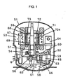
- Fig. 1 is a vertical cross section of a compressor in accordance with the first exemplary embodiment of the present invention
- Fig. 2 is a lateral cross section of a rotor shown in Fig. 1 .
- the compressor comprises the following elements:
- Compressing section 52 comprises the elements below:
- Bearing 57 is mounted to cylinder block 60 with bolt B.
- valve chamber 63 including a discharging valve and a sucking valve (both are not shown) is attached.
- Suction muffler 64 is mounted on the sucking valve side in valve chamber 63.
- oil pipe 65 is attached on the tip of crank 56 for guiding lubricant 66 pooled in the bottom of container 51 to the sliding parts of compressing section 52, so that smooth lubrication is expected.
- Motor 53 comprises the following elements:
- Rotor 55 is detailed with reference to Fig. 2 .
- two pairs of permanent magnets 70a and 70b are buried as follows: Magnets 70a and 70b are plate-shaped rare earth magnet made of neodymium-iron-boron system ferro-magnet. Two pieces of the magnets are butted each other to form a hill with angle alpha ', and they are buried axially in rotor core 68.
- First pair 70a is buried such that S pole faces outward of the rotor, and N pole faces inward of the rotor.
- Second pair 70b is buried such that N pole faces outward of the rotor, and S pole faces inward of the rotor.
- the first pair forms one rotor pole and the second pair forms another rotor pole.
- the entire rotor 55 has two poles. Width of each magnet is referred to as P'.
- Magnets 70a and 70b can be magnetized before they are inserted into rotor core 68 or after the insertion. It is preferable to magnetize the magnetic substance to be a permanent magnet after the substance is inserted and fixed because better operation is expected.
- One pair of magnets are placed to shape in a hill, thereby forming one rotor pole; however, an arc-shaped one piece of magnet can be used because it can also form one rotor pole.
- magnets of one pair are disposed in a hill shape to form one rotor pole; however, one piece of an arc-shaped permanent magnet may form one rotor pole.
- Numbers of conductive bars 71 are provided to rotor core 68, and shorting grommets 72 cover both ends in an axial direction of rotor core 68.
- Bars 71 and grommets 72 are unitarily formed by aluminum diecasting, so that a starter cage-shaped conductor is formed.
- Terminal plates 73 made of non-magnetic material are disposed at both the ends of buried magnets 70a and 70b in the axial direction in order to secure the magnets from coming off.
- barriers 74 for preventing the magnetic fluxes from shorting between the magnets are provided in slot-shaped holes formed in the axial direction of rotor core 68.
- bearing 57 extending inside bored section 69 is made of aluminum diecasting, i.e. non-magnetic material, magnetic attraction does not work between an inner wall of bored section 69 and an outer wall of bearing 57, so that no loss torque is produced. Further, bearing 57 does not attract the magnetic fluxes, therefore, eddy-current-loss within bearing 57 - due to flowing of magnetic fluxes into bearing 57 - does not occur.
- Fig. 3 is a vertical cross section of a compressor in accordance with the second exemplary embodiment of the present invention. This second embodiment differs from the first one in the following points:
- Fig. 4 is a vertical cross section of a compressor in accordance with the third exemplary embodiment of the present invention.
- First bearing 75 is made of non-magnetic material such as aluminum diecasting and shaft 54 is inserted therein.
- Cylinder block 76 is made of iron-system casting, and includes cylinder 59 and second bearing 77 in which shaft 54 is inserted.
- Cylinder 59 forms compressing chamber 62 by sliding piston 58 which is mounted to crank 56 of shaft 54 via connecting rod 61.
- First bearing 75 extends inside bored section 69 of rotor core 68, and fits in second bearing 77 of cylinder block 76 outside bored section 69.
- This structure allows magnetic attraction not to work between an inner wall of bored section 69 and an outer wall of bearing 75, so that neither loss torque nor eddy-current-loss within bearing 75 occurs, and thus a highly efficient compressor is obtainable.
- bearing 75 is made of aluminum-system material; however, the material may be other non-magnetic materials such as copper-system, ceramic substances. Only first bearing 75 can be made of non-magnetic material, and second bearing 77 and cylinder block 76 are unitarily formed-both the elements can be made of inexpensive iron-system material. As a result, a highly efficient and inexpensive compressor is obtainable.
- the self-starting synchronous motor using the permanent magnets is used as an example.
- a dc brush-less motor having two poles can produce the same advantage provided that the permanent magnets are used in the same way, and positional relations between the bored section and the bearing are set in the same manner as those embodiments.
- the dc brush-less motor only does not have conductive bars or shorting grommet, i.e., cage-shaped conductor for starting, on the other hand, it has permanent magnets buried in a rotor, and this structure is common to the self-starting synchronous motor.
- the permanent magnets made of rare-earth-magnet are used. Since the rare-earth-magnet can produce strong magnetic force, the motor and the compressor can be downsized and light weighted.
- This compressor comprises a compressing section accommodated in a hermetic container and a motor section-coupled to the compressing section for driving the compressing section.
- the motor section has a bored section on an end of the compressing section side and a motor having two rotor poles and also including a rotor core in which permanent magnets are buried.
- the compressing section includes a bearing made of non-magnetic material and extending inside the bored section. This structure reduces both of loss torque due to magnetic attraction between an inner wall of the bored section and the bearing, and eddy-current-loss in the bearing, so that a highly efficient compressor is obtainable.
Landscapes
- Engineering & Computer Science (AREA)
- Mechanical Engineering (AREA)
- General Engineering & Computer Science (AREA)
- Power Engineering (AREA)
- Compressor (AREA)
- Permanent Field Magnets Of Synchronous Machinery (AREA)
- Applications Or Details Of Rotary Compressors (AREA)
- Connection Of Motors, Electrical Generators, Mechanical Devices, And The Like (AREA)
Description
- The present invention relates to an electric compressor used in a freezer, refrigerator, or air-conditioner. More particularly it relates to a highly efficient electric compressor in which loss torque and iron loss due to magnetic attraction are reduced. The magnetic attraction is produced at a bearing in a compressing section jointed to a motor section of the compressor.
- A prior art is described with reference to
Fig. 5 where a reciprocal electric compressor is shown. - In
Fig. 5 , the compressor comprises hermetic container 1, compressingsection 2 disposed at lower part of the container, andmotor section 3 disposed above the compressing section.Shaft 4 mounted torotor 14 ofmotor section 3 has crank 4a on its tip. -
Cylinder block 5 formed of a casting made of iron system material comprises bearing 6, in whichshaft 4 is inserted, andcylinder 7 formed at right angles withbearing 6. - Piston 9 is linked to crank 4a via connecting
rod 8. Whenmotor section 3 is driven, rotating movement ofshaft 4 is converted to reciprocal movement by crank 4a, and delivered topiston 9 viarod 8, so thatpiston 9 slides with respect to inner wall ofcylinder 7.Compressing chamber 10 is formed bycylinder 7 andpiston 9.Oil pipe 11 is mounted to a tip of crank 4a, andlubricant 12 pooled at the bottom of hermetic container 1 is lubricated to compressingsection 2 andshaft 4 throughoil pipe 11, so that respective sliding sections move smoothly. -
Motor 3 is a two-pole induction motor comprising the following elements: (a)stator 13 formed of winding-wound-iron-core made of laminated magnetic sheets, and (b)rotor 14 formed ofrotor iron core 15 with a secondary conductor, the rotor iron core being made of laminated magnetic sheets. -
Bored section 16 is provided at the end of rotor-iron-core 15 on the side of compressingsection 2, and bearing 6 extends insidebored section 16. - An operation of the conventional reciprocal compressor of which structure is discussed above is described hereinafter.
- When
rotor 14 spins,piston 9 performs reciprocal movement via connectingrod 8 linked to crank 4a ofshaft 4, so thatpiston 9 compresses coolant gas incompressing chamber 10. The compressed gas is discharged through a discharging pipe (not shown) to a system such as a freezer, refrigerator, or air-conditioner. - Regarding the lubrication to respective sliding sections such as bearing 6,
cylinder 7, connectingrod 8 andpiston 9 of compressingsection 2,oil pipe 11 mounted to lower end ofshaft 4 rotates and pumps uplubricant 12 for lubrication. - Recently, reducing the power consumption of freezers, refrigerators, and air-conditioners has drawn attention because of energy saving tendency, and lower profiles of those apparatuses have been studied because of downsizing requirement. The rotor is disposed as close as possible to the compressing section, and a part of bearing extends inside the bored section, thereby regulating undesirable rotating deflection of the rotor and lowering the total height of the compressor. Thus the downsizing requirement is satisfied. However, power saving of the motor, which consumes the largest power in the freezing system, has not yet arrived at a satisfactory level.
- In the conventional two-pole induction motor used in compressors, magnetic steel sheets of lower iron loss has been employed, a shape of the core has been optimized, or volume of materials used has been increased, in order to raise the efficiency of the motor. The induction motor, however, needs the exciting power for forming a magnetic circuit in addition to the power for producing torque as well as rotating load. Accordingly, efficiency improvement of the motor tends to be saturated, and it is difficult to expect a further substantial improvement of the efficiency.
- A self-starting-synchronous-type two-pole motor using permanent magnets draws attention as another measures for increasing the efficiency of the motor. Because the permanent magnets are buried in the rotor, thereby eliminating the exciting power.
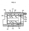
- An example of this self-starting-synchronous-motor is described with reference to
Figs. 6 and7 . Regarding the entire compressor, only the motor is changed, and the changed points are detailed hereinafter. -
Rotor 17 of the synchronous motor comprisesiron core 18 made of laminated magnetic steel sheets andshaft hole 19 for receivingshaft 4 to fit intocore 18.Bored section 20 is provided at the end ofcore 18 in an axial direction. It is not shown in the drawings, but a part of bearing 6 of acylinder block 5 extends insidebored section 20. - Two pieces of plate-type
permanent magnet 21 butt each other and form angle alpha to shape in a hill. Two pairs of thesemagnets 21 are inserted intorotor 17. A first pair of two magnets are placed such that S pole faces outside the rotor and N pole faces inside the rotor. A second pair of two magnets are placed such that N pole faces outside the rotor and S pole faces inside the rotor. Thus the first pair forms a rotor pole and the second pair forms another pole, so thatentire rotor 17 has two poles. The width ofmagnet 21 is referred to as "P". - A starter cage-shaped conductor is unitarily formed by aluminum diecasting comprising numbers of
conductive bars 22 provided tocore 18 and shortinggrommets 23 covering both ends ofcore 18 in an axial direction. - Both end-faces of
core 18 in the axial direction haveprotective terminal plates 24 made of non-magnetic material for securingmagnets 21 from coming off.Barriers 25, for preventing magnetic flux between the permanent magnets from shorting, are provided tocore 18.Barriers 25 are unitarily formed with the starter cage-shaped conductor by the aluminum diecasting. - The flow of magnetic flux from
magnet 21 is schematically described with reference toFig. 7 using the arrow marked lines. The magnetic flux from N poles of twomagnets 21 placed at upper side ofFig. 7 travels mainly through the center section ofcore 18 and is attracted to S poles of twomagnets 21 placed at lower side ofFig. 7 . Thus the magnetic density through core section 18a around theouter rim 20a of bored section becomes substantially high. - As such, self-starting-synchronous type motor using permanent magnets can be used instead of the conventional induction motor. However, since bearing 6 made of iron-system material exists inside
bored section 20, magnetic attraction works between the inner wall of bored section excited and the outer wall ofbearing 6. The magnetic attraction produces loss torque which lowers the torque produced by the motor, and yet, magnetic flux ofmagnet 21 travels to bearing 6 and produces eddy-current-loss. The motor needs another power to compensate the loss torque and eddy-current-loss in order to continue operating, and this prevents the efficiency from increasing. -
JP 2000-134882 A -
EP 0 622 885 A2 discloses a rotor of an electric motor for a compressor, which reduces the generation of eddy current and the flux leakage between adjacent poles. For this purpose the rotor comprises at both ends of the rotor core concentric end surface members formed from non-magnetic material. The rotary shaft and part of the bearing, which is fixed to the casing of the cylinder of the compressor, is passed through a concentric hole of the end surface facing the compressor. - The present invention addresses the problem discussed above, and aims to provide a highly efficient electric compressor in which loss torque due to magnetic attraction and iron loss (particularly eddy-current-loss) in the bearing are reduced by the features of claim 1 and
claim 2. Preferred embodiments are addressed in the subclaims. -
-
Fig. 1 is a vertical cross section of a compressor in accordance with a first exemplary embodiment of the present invention. -
Fig. 2 is a lateral cross section of a rotor shown inFig. 1 . -
Fig. 3 is a vertical cross section of a compressor in accordance with a second exemplary embodiment of the present invention. -
Fig. 4 is a vertical cross section of a compressor in accordance with a third exemplary embodiment of the present invention. -
Fig. 5 is a vertical cross section of a conventional compressor. -
Fig. 6 is a cross section of a rotor taken along an axial direction in a conventional two-pole self-starting-synchronous motor having permanent magnets. -
Fig. 7 is a lateral cross section of a conventional rotor. - The exemplary embodiments of the present invention are demonstrated with reference to the accompanying drawings.
-
Fig. 1 is a vertical cross section of a compressor in accordance with the first exemplary embodiment of the present invention, andFig. 2 is a lateral cross section of a rotor shown inFig. 1 . - In
Fig. 1 , the compressor comprises the following elements: - a
compressing section 52 disposed at the lower section ofhermetic container 51; and a self-starting-synchronous motor 53 having permanent magnets, themotor 53 being disposed above the compressingsection 52.
Shaft 54 mounted torotor 55 ofmotor 53 has crank 56. - Compressing
section 52 comprises the elements below: - bearing 57, made of aluminum diecasting and non-magnetic material, in which
shaft 54 is inserted; and -
cylinder block 60, made of iron-system casting, havingcylinder 59 in whichpiston 58 slides. -
Bearing 57 is mounted tocylinder block 60 with bolt B. On the tip ofcylinder 59,valve chamber 63 including a discharging valve and a sucking valve (both are not shown) is attached.Suction muffler 64 is mounted on the sucking valve side invalve chamber 63. On the tip ofcrank 56,oil pipe 65 is attached for guidinglubricant 66 pooled in the bottom ofcontainer 51 to the sliding parts of compressingsection 52, so that smooth lubrication is expected. -
Motor 53 comprises the following elements: -
stator 67 including stator core made of laminated magnetic steel sheets having thickness L1, where a winding is wound on the core ; and -
rotor 55 includingrotor core 68 made of laminated magnetic steel sheets. -
Rotor 55 is detailed with reference toFig. 2 . Inrotor core 68, two pairs ofpermanent magnets Magnets rotor core 68.First pair 70a is buried such that S pole faces outward of the rotor, and N pole faces inward of the rotor.Second pair 70b is buried such that N pole faces outward of the rotor, and S pole faces inward of the rotor. As such, the first pair forms one rotor pole and the second pair forms another rotor pole. Eventually, theentire rotor 55 has two poles. Width of each magnet is referred to as P'. -
Magnets rotor core 68 or after the insertion. It is preferable to magnetize the magnetic substance to be a permanent magnet after the substance is inserted and fixed because better operation is expected. - One pair of magnets are placed to shape in a hill, thereby forming one rotor pole; however, an arc-shaped one piece of magnet can be used because it can also form one rotor pole.
- In this embodiment, magnets of one pair are disposed in a hill shape to form one rotor pole; however, one piece of an arc-shaped permanent magnet may form one rotor pole.
- Numbers of
conductive bars 71 are provided torotor core 68, and shortinggrommets 72 cover both ends in an axial direction ofrotor core 68.Bars 71 andgrommets 72 are unitarily formed by aluminum diecasting, so that a starter cage-shaped conductor is formed.Terminal plates 73 made of non-magnetic material are disposed at both the ends of buriedmagnets Fig. 2 ,barriers 74 for preventing the magnetic fluxes from shorting between the magnets are provided in slot-shaped holes formed in the axial direction ofrotor core 68. When the starter cage-shaped conductor is formed, the aluminum diecasting is filled into these holes to formbarriers 74. - The flows of magnetic fluxes of
magnets Fig. 2 . - The magnetic fluxes from N pole of two
magnets 70a shown in the upper section ofFig. 2 travel throughrotor core 68 around the rim ofbored section 69 in a concentrated manner, and are attracted to S pole of twomagnets 70b shown in lower section ofFig. 2 . - At this time, narrow magnetic paths are partially formed in
rotor core 68, thus magnetic flux density becomes excessively high. However, since bearing 57 extending insidebored section 69 is made of aluminum diecasting, i.e. non-magnetic material, magnetic attraction does not work between an inner wall ofbored section 69 and an outer wall of bearing 57, so that no loss torque is produced. Further, bearing 57 does not attract the magnetic fluxes, therefore, eddy-current-loss within bearing 57 - due to flowing of magnetic fluxes into bearing 57 - does not occur. - High efficiency of
synchronous motor 53 using the permanent magnets is thus reflected to the compressor. As a result, a highly efficient compressor is obtainable. -
Fig. 3 is a vertical cross section of a compressor in accordance with the second exemplary embodiment of the present invention. This second embodiment differs from the first one in the following points: - In the first embodiment, as shown in
Fig. 1 , bearing 57 is fixed tocylinder block 60 with bolt B; however, in the second embodiment shown inFig. 3 , bearing 57 can be press-fit or shrinkage-fit incylinder block 60. Other elements working in the same way as those in the first embodiment bear the same reference marks as the first embodiment, and the descriptions thereof are thus omitted. They produce the same advantage as they did in the first embodiment. -
Fig. 4 is a vertical cross section of a compressor in accordance with the third exemplary embodiment of the present invention. - In
Fig. 4 , the elements working in the same way as those in the first embodiment shown inFig. 1 bear the same reference marks as in the first embodiment, and the descriptions thereof are thus omitted. - First bearing 75 is made of non-magnetic material such as aluminum diecasting and
shaft 54 is inserted therein. Cylinder block 76 is made of iron-system casting, and includescylinder 59 andsecond bearing 77 in whichshaft 54 is inserted.Cylinder 59forms compressing chamber 62 by slidingpiston 58 which is mounted to crank 56 ofshaft 54 via connectingrod 61. First bearing 75 extends insidebored section 69 ofrotor core 68, and fits insecond bearing 77 of cylinder block 76 outsidebored section 69. - This structure allows magnetic attraction not to work between an inner wall of
bored section 69 and an outer wall of bearing 75, so that neither loss torque nor eddy-current-loss within bearing 75 occurs, and thus a highly efficient compressor is obtainable. - The above description tells that bearing 75 is made of aluminum-system material; however, the material may be other non-magnetic materials such as copper-system, ceramic substances. Only first bearing 75 can be made of non-magnetic material, and
second bearing 77 and cylinder block 76 are unitarily formed-both the elements can be made of inexpensive iron-system material. As a result, a highly efficient and inexpensive compressor is obtainable. - In the previous embodiments, i.e., from the first embodiment to the fourth one, the self-starting synchronous motor using the permanent magnets is used as an example. However, a dc brush-less motor having two poles can produce the same advantage provided that the permanent magnets are used in the same way, and positional relations between the bored section and the bearing are set in the same manner as those embodiments. Because the dc brush-less motor only does not have conductive bars or shorting grommet, i.e., cage-shaped conductor for starting, on the other hand, it has permanent magnets buried in a rotor, and this structure is common to the self-starting synchronous motor.
- Also in the previous embodiments, the permanent magnets made of rare-earth-magnet are used. Since the rare-earth-magnet can produce strong magnetic force, the motor and the compressor can be downsized and light weighted.
- This compressor comprises a compressing section accommodated in a hermetic container and a motor section-coupled to the compressing section for driving the compressing section. The motor section has a bored section on an end of the compressing section side and a motor having two rotor poles and also including a rotor core in which permanent magnets are buried. The compressing section includes a bearing made of non-magnetic material and extending inside the bored section. This structure reduces both of loss torque due to magnetic attraction between an inner wall of the bored section and the bearing, and eddy-current-loss in the bearing, so that a highly efficient compressor is obtainable.
Claims (5)
- A compressor comprising:a compressing section (52) accommodated in a hermetic container (51); anda motor section, coupled to said compressing section (52), for driving said compressing section (52), said motor section including:characterized in that said compressing section (52) includes a bearing (57) made of non-magnetic material and extending inside the bored section (69).a bored section (69) on an end of the compressing section (52)side;a motor (53) having two poles of a rotor (55)and a rotor core (68) in which a permanent magnet (70a, 70b) is buried,
- A compressor comprising:a compressing section (52) accommodated in a hermetic container (51) wherein said compressing section (52) includes a cylinder block (76) ; anda motor section, coupled to said compressing section (52), for driving said compressing section (52), said motor section including:characterized in that said compressing section (52) includes a first bearing (75) and a second bearing (77) of which the first bearing (75) extends inside the bored section (69), and at least the first bearing (75) is made of non-magnetic material, and the second bearing (77) and the cylinder block (76) are unitarily formed with each other by using iron-system material.a bored section (69) on an end of the compressing section (52) side;a motor (53) having two poles of a rotor (55) and a rotor core (68) in which a permanent magnet (70a, 70b) is buried,
- The compressor as defined in Claims 1 or 2, further comprising a plurality of cage-shaped starting conductive bars (71) around an outer rim of the iron core (68), wherein the rotor (55) has a plurality of permanent magnets (70a, 70b) buried inside of the conductive bars (71).
- The compressor as defined in Claims 1 or 2, wherein the permanent magnets (70a, 70b) are made of rare-earth-magnet.
- The compressor as defined in Claim 3, wherein the permanent magnets (70a, 70b) are made of rare-earth-magnet.
Applications Claiming Priority (3)
| Application Number | Priority Date | Filing Date | Title |
|---|---|---|---|
| JP18876299 | 1999-07-02 | ||
| JP18876299 | 1999-07-02 | ||
| PCT/JP2000/004322 WO2001002728A1 (en) | 1999-07-02 | 2000-06-30 | Electric compressor |
Publications (3)
| Publication Number | Publication Date |
|---|---|
| EP1111240A1 EP1111240A1 (en) | 2001-06-27 |
| EP1111240A4 EP1111240A4 (en) | 2004-08-04 |
| EP1111240B1 true EP1111240B1 (en) | 2009-06-03 |
Family
ID=16229339
Family Applications (1)
| Application Number | Title | Priority Date | Filing Date |
|---|---|---|---|
| EP00942404A Expired - Lifetime EP1111240B1 (en) | 1999-07-02 | 2000-06-30 | Electric compressor |
Country Status (10)
| Country | Link |
|---|---|
| US (1) | US6547538B1 (en) |
| EP (1) | EP1111240B1 (en) |
| KR (1) | KR100507786B1 (en) |
| CN (1) | CN1179126C (en) |
| AU (1) | AU756428B2 (en) |
| BR (1) | BR0006886A (en) |
| DE (1) | DE60042310D1 (en) |
| SG (1) | SG131758A1 (en) |
| TW (1) | TW486543B (en) |
| WO (1) | WO2001002728A1 (en) |
Families Citing this family (21)
| Publication number | Priority date | Publication date | Assignee | Title |
|---|---|---|---|---|
| JP2004245073A (en) * | 2003-02-12 | 2004-09-02 | Matsushita Electric Ind Co Ltd | Electric compressor |
| JP2004332648A (en) * | 2003-05-09 | 2004-11-25 | Matsushita Electric Ind Co Ltd | Hermetic electric compressor |
| JP2004332688A (en) * | 2003-05-12 | 2004-11-25 | Matsushita Electric Ind Co Ltd | Electric compressor |
| KR100531818B1 (en) * | 2003-06-18 | 2005-11-30 | 엘지전자 주식회사 | Rotor structure of line start pm motor |
| JP2008501080A (en) * | 2004-05-28 | 2008-01-17 | 松下電器産業株式会社 | Hermetic compressor |
| WO2006057418A1 (en) * | 2004-11-24 | 2006-06-01 | Matsushita Electric Industrial Co., Ltd. | Hermetic compressor |
| CN100427757C (en) * | 2004-11-24 | 2008-10-22 | 松下电器产业株式会社 | hermetic compressor |
| KR100748538B1 (en) * | 2005-11-30 | 2007-08-13 | 엘지전자 주식회사 | Synchronous reluctance motor and compressor with same |
| US20070132330A1 (en) * | 2005-12-12 | 2007-06-14 | Fei Renyan W | Fan assemblies employing LSPM motors and LSPM motors having improved synchronization |
| JP2008138526A (en) * | 2006-11-30 | 2008-06-19 | Daikin Ind Ltd | Compressor |
| GB2467966B (en) * | 2009-02-24 | 2013-04-03 | Dyson Technology Ltd | Rotor assembly |
| GB2467965B (en) * | 2009-02-24 | 2015-04-22 | Dyson Technology Ltd | Rotor assembly |
| CN102444580B (en) * | 2010-09-30 | 2016-03-23 | 艾默生电气公司 | With the digital compressor of across-the-line starting brushless permanent magnet electromotor |
| GB2493974B (en) | 2011-08-26 | 2014-01-15 | Dyson Technology Ltd | Bearing assembly |
| CN103790799A (en) * | 2012-11-02 | 2014-05-14 | 海尔集团公司 | Linear compressor |
| JP6119962B2 (en) * | 2012-11-15 | 2017-04-26 | 株式会社豊田自動織機 | Electric compressor |
| US9518572B2 (en) * | 2014-02-10 | 2016-12-13 | Haier Us Appliance Solutions, Inc. | Linear compressor |
| US10954944B2 (en) * | 2015-04-27 | 2021-03-23 | Emerson Climate Technologies, Inc. | Compressor having counterweight assembly |
| RU2745598C2 (en) * | 2016-10-07 | 2021-03-29 | Битцер Кюльмашиненбау Гмбх | Semihermetic refrigerant compressor |
| KR102016250B1 (en) | 2018-02-08 | 2019-08-29 | 엘지전자 주식회사 | Dual rotor type motor improved stator structure |
| RU2771541C1 (en) * | 2021-03-17 | 2022-05-05 | Битцер Кюльмашиненбау Гмбх | Semihermetic refrigerant compressor (variants) |
Family Cites Families (11)
| Publication number | Priority date | Publication date | Assignee | Title |
|---|---|---|---|---|
| JPH0638474A (en) * | 1992-07-10 | 1994-02-10 | Toshiba Corp | Magnetizing method for rotor of brushless motor and magnetizing jig |
| JPH08247030A (en) * | 1995-03-14 | 1996-09-24 | Matsushita Refrig Co Ltd | Electric compressor |
| US6047460A (en) * | 1996-01-23 | 2000-04-11 | Seiko Epson Corporation | Method of producing a permanent magnet rotor |
| JPH1075542A (en) * | 1996-08-29 | 1998-03-17 | Aichi Emerson Electric Co Ltd | Motor for driving compressor |
| KR100190141B1 (en) * | 1996-10-17 | 1999-06-01 | 윤종용 | Closed-loop reciprocating compressor with oil guide ball |
| IT1292289B1 (en) * | 1997-04-28 | 1999-01-29 | Embraco Europ Srl | HERMETIC MOTOR-COMPRESSOR FOR REFRIGERATING MACHINES. |
| JPH10318132A (en) * | 1997-05-22 | 1998-12-02 | Matsushita Refrig Co Ltd | Electric compressor |
| JPH11303746A (en) * | 1998-04-20 | 1999-11-02 | Matsushita Refrig Co Ltd | Motor-driven compressor |
| KR100295178B1 (en) * | 1998-04-28 | 2001-09-07 | 구보다 다다시 | Linear motor and linear compressor |
| JP2000134882A (en) * | 1998-10-21 | 2000-05-12 | Matsushita Electric Ind Co Ltd | Permanent magnet motor rotor and compressor equipped with same |
| KR100318598B1 (en) * | 2000-03-07 | 2001-12-28 | 이충전 | Noise Falling Apparatus Of a Compressor |
-
2000
- 2000-06-30 DE DE60042310T patent/DE60042310D1/en not_active Expired - Lifetime
- 2000-06-30 BR BR0006886-1A patent/BR0006886A/en not_active IP Right Cessation
- 2000-06-30 US US09/786,594 patent/US6547538B1/en not_active Expired - Lifetime
- 2000-06-30 KR KR10-2001-7002783A patent/KR100507786B1/en not_active Expired - Fee Related
- 2000-06-30 AU AU57063/00A patent/AU756428B2/en not_active Ceased
- 2000-06-30 SG SG200301507-0A patent/SG131758A1/en unknown
- 2000-06-30 EP EP00942404A patent/EP1111240B1/en not_active Expired - Lifetime
- 2000-06-30 CN CNB008012946A patent/CN1179126C/en not_active Expired - Fee Related
- 2000-06-30 WO PCT/JP2000/004322 patent/WO2001002728A1/en not_active Ceased
- 2000-07-01 TW TW089113102A patent/TW486543B/en not_active IP Right Cessation
Also Published As
| Publication number | Publication date |
|---|---|
| DE60042310D1 (en) | 2009-07-16 |
| AU756428B2 (en) | 2003-01-16 |
| EP1111240A4 (en) | 2004-08-04 |
| SG131758A1 (en) | 2007-05-28 |
| WO2001002728A1 (en) | 2001-01-11 |
| US6547538B1 (en) | 2003-04-15 |
| AU5706300A (en) | 2001-01-22 |
| CN1316037A (en) | 2001-10-03 |
| KR20010082186A (en) | 2001-08-29 |
| EP1111240A1 (en) | 2001-06-27 |
| BR0006886A (en) | 2001-06-12 |
| TW486543B (en) | 2002-05-11 |
| CN1179126C (en) | 2004-12-08 |
| KR100507786B1 (en) | 2005-08-17 |
Similar Documents
| Publication | Publication Date | Title |
|---|---|---|
| US6547538B1 (en) | Electric compressor | |
| US20040191094A1 (en) | Electric compressor | |
| JP4005169B2 (en) | Compressor | |
| JP4529241B2 (en) | Electric compressor | |
| US20070284961A1 (en) | Permanent Magnet Synchronous Motor, Rotor of the Same, and Compressor Using the Same | |
| JP2007327497A (en) | Compressor | |
| US20060147326A1 (en) | Hermetically sealed compressor | |
| JPWO2008062789A1 (en) | Rotary compressor and refrigeration cycle apparatus | |
| US7866957B2 (en) | Hermetic compressor | |
| CN101354026B (en) | hermetic compressor | |
| JP2005168097A (en) | Electric motor and rotary compressor | |
| JP4031454B2 (en) | Compressor | |
| JP2006144731A (en) | Compressor | |
| JP2010246229A (en) | Compressor mounted with synchronous motor and method for manufacturing synchronous motor | |
| JP2001339929A (en) | Electric compressor | |
| KR100556248B1 (en) | Synchronous Motor | |
| KR200165731Y1 (en) | Stator structure of a compressor | |
| KR100556251B1 (en) | Synchronous Motor | |
| KR20070021020A (en) | Hermetic compressor | |
| JP2007040139A (en) | Compressor | |
| JP2005180312A (en) | Electric compressor |
Legal Events
| Date | Code | Title | Description |
|---|---|---|---|
| PUAI | Public reference made under article 153(3) epc to a published international application that has entered the european phase |
Free format text: ORIGINAL CODE: 0009012 |
|
| 17P | Request for examination filed |
Effective date: 20010301 |
|
| AK | Designated contracting states |
Kind code of ref document: A1 Designated state(s): AT BE CH CY DE DK ES FI FR GB GR IE IT LI LU MC NL PT |
|
| AX | Request for extension of the european patent |
Free format text: AL;LT;LV;MK;RO;SI |
|
| RAP1 | Party data changed (applicant data changed or rights of an application transferred) |
Owner name: MATSUSHITA ELECTRIC INDUSTRIAL CO., LTD. Owner name: MATSUSHITA REFRIGERATION COMPANY |
|
| RBV | Designated contracting states (corrected) |
Designated state(s): DE ES GB IT |
|
| A4 | Supplementary search report drawn up and despatched |
Effective date: 20040617 |
|
| RIC1 | Information provided on ipc code assigned before grant |
Ipc: 7H 02K 21/04 B Ipc: 7F 04B 39/00 A Ipc: 7F 04B 39/12 B Ipc: 7F 04B 35/04 B Ipc: 7H 02K 7/08 B |
|
| RAP1 | Party data changed (applicant data changed or rights of an application transferred) |
Owner name: MATSUSHITA REFRIGERATION COMPANY Owner name: PANASONIC CORPORATION |
|
| RAP1 | Party data changed (applicant data changed or rights of an application transferred) |
Owner name: PANASONIC CORPORATION |
|
| GRAP | Despatch of communication of intention to grant a patent |
Free format text: ORIGINAL CODE: EPIDOSNIGR1 |
|
| GRAS | Grant fee paid |
Free format text: ORIGINAL CODE: EPIDOSNIGR3 |
|
| GRAA | (expected) grant |
Free format text: ORIGINAL CODE: 0009210 |
|
| AK | Designated contracting states |
Kind code of ref document: B1 Designated state(s): DE ES GB IT |
|
| REG | Reference to a national code |
Ref country code: GB Ref legal event code: FG4D |
|
| REF | Corresponds to: |
Ref document number: 60042310 Country of ref document: DE Date of ref document: 20090716 Kind code of ref document: P |
|
| PG25 | Lapsed in a contracting state [announced via postgrant information from national office to epo] |
Ref country code: ES Free format text: LAPSE BECAUSE OF FAILURE TO SUBMIT A TRANSLATION OF THE DESCRIPTION OR TO PAY THE FEE WITHIN THE PRESCRIBED TIME-LIMIT Effective date: 20090914 |
|
| PLBE | No opposition filed within time limit |
Free format text: ORIGINAL CODE: 0009261 |
|
| STAA | Information on the status of an ep patent application or granted ep patent |
Free format text: STATUS: NO OPPOSITION FILED WITHIN TIME LIMIT |
|
| 26N | No opposition filed |
Effective date: 20100304 |
|
| GBPC | Gb: european patent ceased through non-payment of renewal fee |
Effective date: 20090903 |
|
| PG25 | Lapsed in a contracting state [announced via postgrant information from national office to epo] |
Ref country code: GB Free format text: LAPSE BECAUSE OF NON-PAYMENT OF DUE FEES Effective date: 20090903 |
|
| PGFP | Annual fee paid to national office [announced via postgrant information from national office to epo] |
Ref country code: IT Payment date: 20130618 Year of fee payment: 14 |
|
| PG25 | Lapsed in a contracting state [announced via postgrant information from national office to epo] |
Ref country code: IT Free format text: LAPSE BECAUSE OF NON-PAYMENT OF DUE FEES Effective date: 20140630 |
|
| PGFP | Annual fee paid to national office [announced via postgrant information from national office to epo] |
Ref country code: DE Payment date: 20160622 Year of fee payment: 17 |
|
| REG | Reference to a national code |
Ref country code: DE Ref legal event code: R119 Ref document number: 60042310 Country of ref document: DE |
|
| PG25 | Lapsed in a contracting state [announced via postgrant information from national office to epo] |
Ref country code: DE Free format text: LAPSE BECAUSE OF NON-PAYMENT OF DUE FEES Effective date: 20180103 |