EP0622885A2 - Rotor of electric motor for compressor - Google Patents
Rotor of electric motor for compressor Download PDFInfo
- Publication number
- EP0622885A2 EP0622885A2 EP94302956A EP94302956A EP0622885A2 EP 0622885 A2 EP0622885 A2 EP 0622885A2 EP 94302956 A EP94302956 A EP 94302956A EP 94302956 A EP94302956 A EP 94302956A EP 0622885 A2 EP0622885 A2 EP 0622885A2
- Authority
- EP
- European Patent Office
- Prior art keywords
- rotor
- rotor core
- end surface
- electric motor
- surface member
- Prior art date
- Legal status (The legal status is an assumption and is not a legal conclusion. Google has not performed a legal analysis and makes no representation as to the accuracy of the status listed.)
- Granted
Links
Images









Classifications
-
- H—ELECTRICITY
- H02—GENERATION; CONVERSION OR DISTRIBUTION OF ELECTRIC POWER
- H02K—DYNAMO-ELECTRIC MACHINES
- H02K1/00—Details of the magnetic circuit
- H02K1/06—Details of the magnetic circuit characterised by the shape, form or construction
- H02K1/22—Rotating parts of the magnetic circuit
- H02K1/27—Rotor cores with permanent magnets
- H02K1/2706—Inner rotors
- H02K1/272—Inner rotors the magnetisation axis of the magnets being perpendicular to the rotor axis
- H02K1/274—Inner rotors the magnetisation axis of the magnets being perpendicular to the rotor axis the rotor consisting of two or more circumferentially positioned magnets
- H02K1/2753—Inner rotors the magnetisation axis of the magnets being perpendicular to the rotor axis the rotor consisting of two or more circumferentially positioned magnets the rotor consisting of magnets or groups of magnets arranged with alternating polarity
- H02K1/276—Magnets embedded in the magnetic core, e.g. interior permanent magnets [IPM]
-
- H—ELECTRICITY
- H02—GENERATION; CONVERSION OR DISTRIBUTION OF ELECTRIC POWER
- H02K—DYNAMO-ELECTRIC MACHINES
- H02K7/00—Arrangements for handling mechanical energy structurally associated with dynamo-electric machines, e.g. structural association with mechanical driving motors or auxiliary dynamo-electric machines
- H02K7/04—Balancing means
-
- H—ELECTRICITY
- H02—GENERATION; CONVERSION OR DISTRIBUTION OF ELECTRIC POWER
- H02K—DYNAMO-ELECTRIC MACHINES
- H02K7/00—Arrangements for handling mechanical energy structurally associated with dynamo-electric machines, e.g. structural association with mechanical driving motors or auxiliary dynamo-electric machines
- H02K7/14—Structural association with mechanical loads, e.g. with hand-held machine tools or fans
-
- H—ELECTRICITY
- H02—GENERATION; CONVERSION OR DISTRIBUTION OF ELECTRIC POWER
- H02K—DYNAMO-ELECTRIC MACHINES
- H02K2205/00—Specific aspects not provided for in the other groups of this subclass relating to casings, enclosures, supports
- H02K2205/12—Machines characterised by means for reducing windage losses or windage noise
Definitions
- the present invention relates to the structure of the rotor of an electric motor for a compressor.
- Conventional rotors of electric motors for a compressor generally has the following structures.
- the rotor described in Japanese Patent Laid-Open No. 52359/1982 is produced by inserting a laminated rotor core and magnetic materials into a metal pipe, and integrally die-casting these elements.
- the rotor described in Japanese Patent Laid-Open No. 246748/1990 is produced by inserting a laminated rotor core and magnetic materials into a metal pipe in the same way as in the above-described rotor, and integrally clamping these elements. At the time of clamping, an air gap portion is provided between adjacent magnetic materials so as to safely separate the poles of the magnetic materials, thereby enhancing the efficiency.
- Japanese Patent Laid-Open No. 185247/1992 discloses another rotor, which is composed of magnetic materials embedded into the salient pole portions of the rotor core which has a salient-pole structure.
- the rotor core with the magnetic materials embedded therein and end surface members for covering both end surface thereof are arranged, and a rotary shaft is integrally press-fitted into the rotor core in this state.
- the conventional rotors having the above-described structures have problems such as much eddy current loss caused by the cage portion of a die-cast material (e.g., zinc and aluminum), much eddy current loss in a metal pipe, and difficulty in the maintenance of the high dimensional accuracy at the time of production due to the projection provided on the rotor core so as to prevent the movement of the magnetic materials.
- a die-cast material e.g., zinc and aluminum
- an eddy current is produced by the secondary conductor in the rotor core, and since part of the magnetic flux produced from the magnetic material is short-circuited in the rotor core (conductor), the operation efficiency of the motor is lowered.
- a rotor of an electric motor for a compressor having a compressing element and an electric motor for driving the compressing element which are accommodated in a single closed container comprising: a rotor core composed of a plurality of laminated iron plates; a first end surface mem- berformed from a nonmagnetic material which has at least a balance weight and a caulking boss for caulking a disk for oil separation and which is disposed at one end of the rotor; a second end surface member formed from a nonmagnetic material which is disposed at the other end of the rotor; and a plurality of caulking members which penetrate the rotor core, the first end surface member and the second end surface member so as to integrally caulk the rotor core, the first end surface member and the second end surface member.
- the rotor core is composed of a plurality of electromagnetic steel plates each having a thickness of not more than 0.5 mm which are integrally laminated by welding or caulking.
- the first end surface member/and or the second end surface member is composed of a die-cast nonmagnetic metal material, a drawn nonmagnetic metal drawing, or a resin material.
- a rotor of an electric motor for a compressor having a compressing element and an electric motor for driving the compressing element which are accommodated in a single closed container comprising: a rotor core composed of a plurality of laminated iron plates which accommodate a plurality of magnetic materials constituting magnetic poles along the outer periphery of the rotor core; a first end surface member formed from a nonmagnetic material which has at least a balance weight and a caulking boss for caulking a disk for oil separation and which is disposed at one end of the rotor; a second end surface member formed from a nonmagnetic material which is disposed at the other end of the rotor; and a plurality of caulking members which are inserted into the respective through holes formed in the first end surface member and leading to the second end surface member through the rotor core so as to integrally caulk the rotor core, the first end surface member and the second end surface member.
- the rotor core is provided with air gaps between the respective adjacent magnetic poles so as to prevent the short circuit of a magnetic flux.
- the air gaps lead to the respective through holes in which the caulking members are inserted.
- the magnetic material is, for example, a magnet of sintered ferrite, a sintered rare earth element, a rare earth element alloy or a plastic containing a rare earth element.
- a rotor of an electric motor for a compressor having a compressing element and an electric motor for driving the compressing element which are accommodated in a single closed container comprising: a rotor core composed of a plurality of laminated iron plates which accommodate a plurality of magnetic materials constituting magnetic poles along the outer periphery of the rotor core; a first end surface member formed from a nonmagnetic material which is disposed at one end of the rotor; a second end surface member formed from a nonmagnetic material which is disposed at the other end of the rotor; and a welding portion for integrally welding the outer peripheral surfaces of the rotor core, the first end surface member and the second end surface member.
- Fig. 1 is a sectional view of a rotary compressor.
- the reference numeral 1 represents a closed container accommodating an electric motor 2 in the upper part and a compressing element 3 driven by the electric motor 2 in the lower part.
- the closed container 1 is produced by bonding and closing the container accommodating the electric motor 2 and a container accommodating the compressing element by high- fequency welding or the like.
- the electric motor 2 is composed of a stator 4 fixed to the inner wall of the closed container 1 and a rotor 5 supported by the inside of the stator 4 in such a manner as to be freely rotatable around a rotary shaft 6.
- the stator 4 is provided with a stator coil 7 for providing the rotor 5 with a rotating magnetic flux .
- the compressing element 3 is provided with a first rotary cylinder 9 and a second rotary cylinder 10 which are separated from each other by a partition plate 8. Eccentric portions 11, 12 which are attached to the cylinders 9 and 10, respectively, are rotated around the rotary shaft 6 with a phase difference of 180 degrees therebetween.
- the reference numerals 13 and 14 represent first and second rollers which rotate in the cylinders 9 and 10, respectively, with the rotations of the eccentric portions 11 and 12.
- Discharge mufflers 19, 20 are attached to the first frame 15 and the second frame 16, respectively, in such a manner as to cover the respective frames 15, 16.
- the cylinder 9 and the discharge muffler 19 communicate with each other through a discharge hole (not shown) formed in the first frame 15, and the cylinder 10 and the discharge muffler 20 communicate with each other through a discharge hole (not shown) formed in the second frame 16.
- a bypass pipe 21 provided on the outside of the closed container 1 communicates with the discharge muffler 20.
- the reference numeral 22 denotes a discharge pipe provided at the top of the closed container 1, and 23, 24 suction pipes connected to the cylinders 9 and 10, respectively.
- a closing terminal 25 supplies electric power from an external equipment to the coil 7 of the stator4. (Lead wires for connecting the stator coil 7 and the closing terminal 25 are not shown).
- the reference numeral 26 represents an oil separation disk which is fixed to the rotary shaft 6 by a bolt 27. The disk 26 may be fixed by a later-described boss.
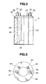
- Fig. 2 is a partially sectional view of the rotor 5 shown in Fig. 1 before the rotary shaft 6 is press-fitted thereinto.
- a rotor core 28 is composed of a plurality of laminated electromagnetic steel plates (iron plates for a rotor) each having a thickness of 0.5 mm and punched into a predetermined shape. The electromagnetic steel plates are caulked with each other and integrally laminated (or integrally welded).
- a first end surface member 30 which is attached to one end of the rotor core 28 has balance weights 33, 34, 35 and 36 for counterbalancing the compressing element 3, and bosses 31, 32 disposed on the balance weights 36 and 35, respectively.
- the first end surface member 30, the balance weights 33 to 36 and the bosses 31 and 32 are integrally formed from a nonmagnetic material such as aluminum and zinc by die-casting or drawing or from a synthetic resin material.
- the positions and the shapes of the bosses 31, 32 are determined in correspondence with the oi I separation disk 26.
- a second end surface member 38 which is attached to the other end of the rotor core 28 is integrally formed into an annular shape from a nonmagnetic material such as aluminum by die-casting or drawing or from a synthetic resin material in the same way as in the first end surface member 30.
- a plurality of welding portions 37 are provided on the outer periphery of the rotor 5 in the axial direction. After the magnetic materials 29 are press-fitted into the rotor core 28 and the first end surface member 30 and the second end surface member 38 are set, these welding portions 37 are simultaneously welded so as to produce the rotor 5.
- Fig. 3 is a plan view of the first end surface member 30 shown in Fig. 2.
- the end surface member 30 has a concentric (annular) shape, and the rotary shaft 6 of the rotor 5 is passed through a shaft hole 39.
- Fig. 4 is a plan view of the second end surface member 38 shown in Fig. 2.
- the end surface member 38 has a concentric (annular) shape, and the rotary shaft 6 of the rotor 5 is passed through a shaft hole 40.
- Fig. 5 is a plan view of the electromagnetic steel plates (iron plates for the rotor) used for the rotor core 28 shown in Fig. 2.
- the reference numerals 41 to 44 denote slots into which the magnetic materials 29 having a section having a figure obtained by removing a small sector from a concentric large sector (this section will be hereinunder referred to as "a fan-shaped section") are press-fitted.
- the slots 41 to 44 are formed in the rotor core 28 along the outer periphery.
- Slits 45 to 48 are provided between the respective adjacent slots 41 to 44 (on the boundaries between the poles). The slits 45 to 48 function as the air gaps for promoting the separation of the respective magnetic poles after the magnetic materials 29 are press-fitted into the slots 41 to 44.
- Fig. 6 is a plan view of a modification of the rotor core 28 shown in Fig. 2.
- the rotor core shown in Fig. 6 is composed of a plurality of laminated electromagnetic steel plates 50 each punched into a shape for forming salient pole portions 51 to 54.
- the reference numerals 55 to 58 denote notched portions for forming the salient pole portions 51 to 54.
- the reference numerals 59 to 62 denote slots into which the magnetic materials 29 are press-fitted, and 63 a shaft hole through which the rotary shaft 6 is passed.
- each of the end surface members 30 and 38 may have the same shape as the respective end surfaces of the rotor core.
- Fig. 7 is a partially sectional view of another embodiment of the rotor of an electric motor for a compressor according to the present invention.
- the reference numeral 101 denotes a rotor core which is composed of a plurality of laminated electromagnetic steel plates (iron plates for a rotor) each having a thickness of 0.5 mm and punched into a predetermined shape.
- the electromagnetic steel plates are caulked with each other and integrally laminated (or integrally welded).
- the reference numeral 102 denotes a magnetic material (the same as the magnetic material shown in Fig. 2).
- the magnetic material 102 is press-fitted or inserted into a slot which is formed in the rotor core 28 in the axial direction.
- a plurality of magnetic materials 102 are disposed in the rotor core 101 along the outer periphery of the rotor core 101.
- Afirst end surface member 103 which is attached to one end of the rotor core 101 has balance weights 104, 105, 106 and 107 for counterbalancing the compressing element 3, and bosses 108, 109 disposed on the balance weights 104 and 107, respectively.
- the first end surface member 103, the balance weights 104 to 107 and the bosses 108 and 109 are integrally formed from a nonmagnetic material such as aluminum and zinc by die-casting or drawing or from a synthetic resin material.
- the positions and the shapes of the bosses 108, 109 are determined in correspondence with the oil separation disk 26.
- a second end surface member 110 which is attached to the other end of the rotor core 101 is integrally formed into an annular shape from a nonmagnetic material such as aluminum by die-casting or drawing orfrom a synthetic resin material in the same way as in the first end surface member 103.
- Caulking members (caulking pins, caulking bolts orthe like) 111 to 114 integrally caulk the first end surface member 103, the rotor core 101 and the second end surface member 110 by utilizing the through holes formed in the first end surface member 103, the rotor core 101 and the second end surface member 110.
- Fig. 8 is a plan view of the first end surface member 103 shown in Fig. 7.
- the end surface member 103 has a concentric (annular) shape, and the rotary shaft 6 of the rotor 5 is passed through a shaft hole 119.
- the reference numerals 115 to 118 represent through holes through which the caulking members 111 to 114, respectively, are passed. Each of the through holes 115 to 118 has appropriate size and shape corresponding to the respective caulking members 111 to 114.
- Fig. 9 is a plan view of the second end surface member 110 shown in Fig. 7.
- the end surface member 110 has a concentric (annular) shape, and the rotary shaft 6 of the rotor 5 is passed through a shaft hole 124.
- the reference numerals 120 to 123 represent through holes through which the caulking members 111 to 114, respectively, are passed. Each of the through holes 120 to 123 has appropriate size and shape corresponding to the respective caulking members 111 to 114.
- Fig. 10 is a plan view of the electromagnetic steel plates (iron plates for the rotor) used for the rotor core 101 shown in Fig. 7.
- the reference numerals 125 to 128 denote slots into which the magnetic materials 102 having a fan-shaped section are press-fitted.
- the slots 125 to 128 are formed in the rotor core 101 along the outer periphery.
- Slits 129 to 132 are provided between the respective adjacent slots 125 to 128 (on the boundaries between the poles).
- the slits 129 to 132 function as air gaps for promoting the separation of the respective magnetic poles after the magnetic materials 102 are press-fitted into the slots 125 to 128.
- the reference numerals 131 to 134 represent through holes through which the caulking members 111 to 114, respectively, are passed.
- Each of the through holes 120 to 123 has appropriate size and shape corresponding to the respective caulking members 111 to 114. They are disposed between the respective adjacent slots 125 to 128 so as to communicate with the respective slits 129 to 132. Since the slits 129 to 132 communicate with the through holes 131 to 134, the air gaps between the adjacent magnetic poles are so enlarged as to reduce the flux leakage and the operation efficiency of the electric motor is enhanced to that degree.
- the reference numeral 135 represents a shaft hole into which the rotary shaft 6 is press-fitted.
- the rotor core 101 and the second end surface member 110 are laid with one on top of another in such a manner that the through holes 115 to 118, 131 to 134 and 120 to 123 communicate with each other, they are integrally caulked by the caulking members 111 to 114 so as to produce the rotor 5.
- Fig. 11 is a plan view of a modification of the rotor core 101 shown in Fig. 7.
- the rotor core shown in Fig. 11 is composed of a plurality of laminated electromagnetic steel plates 140 each punched into a shape for forming salient pole portions 136 to 139.
- the reference numerals 141 to 144 denote notched portions for forming the salient pole portions 136 to 139.
- the reference numerals 145 to 148 denote slots into which the magnetic materials 102 are press-fitted and 149 a shaft hole through which the rotary shaft 6 is passed.
- the reference numerals 150 to 153 represent through holes through which the caulking members 111 to 114, respectively, are passed. Each of the through holes 150 to 153 has appropriate size and shape corresponding to the respective caulking members 111 to 114.
- the end surface members are set, and the rotor 5 is integrally produced by using the caulking members 111 to 114, in the same way as the rotor 5 shown in Fig. 7.
- each of the end surface members may have the same shape as the respective end surfaces of the rotor cores.
- Fig. 12 is a plan view of another modification of the rotor core 101 shown in Fig. 7.
- the reference numerals 154 to 157 denote slots into which the magnetic materials 102 having a fan-shaped section are press-fitted and 158 to 161 slits provided between the respective adjacent slots 154 to 157 (on the boundaries between the poles).
- the slits 158 to 161 function as air gaps for promoting the separation of the respective magnetic poles after the magnetic materials 102 are press-fitted into the slots 154 to 157.
- the reference numerals 162 to 165 represent through holes through which the caulking members 111 to 114, respectively, are passed.
- Each of the through holes 162 to 165 has appropriate size and shape corresponding to the respective caulking members 111 to 114. They are disposed between the respective adjacent slots 154 to 157 so as to communicate with the respective slits 158 to 161. These continuous holes and slits open on the outer periphery of the rotor core.
- the reference numeral 166 represents a shaft hole into which the rotary shaft 6 is press-fitted.
- Fig. 13 is a partially sectional view of sti another embodiment of the rotor 5 of an electric motor for a compressor according to the present invention
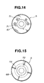
- Fig. 14 is a plan view thereof
- Fig. 15 is a bottom view thereof
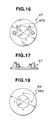
- Fig. 16 is a plan view of the first end surface member of the rotor
- Fig. 17 is a side elevational view thereof
- Fig. 18 is a plan view of the second end surface member of the rotor
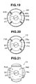
- Fig. 19 is a plan view of the rotor core shown in Fig. 13.
- the reference numeral 69 represents a rotor core and 70 a magnetic material composed of a permanent magnet and inserted into the rotor core 69.
- a first end surface member 67 and a second end surface member 68 formed from a nonmagnetic material similar to that in the above-described embodiments are disposed on the top and the bottom of the rotor core 67 and the magnetic materials 70. These elements are bolted by a plurality of (four in this embodiment) bolts 71 and nuts 72, and the rotary shaft 6 of the electric motor 2 is press-fitted thereinto.
- each of the bolt holes 67a and 68a formed in the first and second end surface members 67 and 68, respectively, is larger than the diameter of each of the bolt hole 69a of the rotor core 69 shown in Fig. 19.
- the rotor core 69 has four slits 69b and and four slots 69c having a fan-shaped section into which magnetic materials 70 having a fan-shaped section are press-fitted.
- Fig. 20 shows a modification of the rotor core 69 shown in Fig. 13.
- bolt holes 73a communicate with slits 73b and these continuous holes open on the outer periphery of the rotor core 73.
- the reference numeral 73c denotes a through hole for inserting the magnetic material 70 thereinto.
- Fig. 21 shows another modification of the rotor core 69 shown in Fig. 13.
- a rotor core 74 shown in Fig. 21 has bolt holes 74a and slots 74c for inserting the plate-like magnetic materials 70 thereinto.
- the machining tolerance in each of the outer and inner diameters of the first and second end surface members 67, 68 and the bolt holes may not be very strict. It is also easy to align the inner peripheries, the outer peripheries and the bolt holes of the first and second end surface members and the rotor core at the time of bolting (or caulking) these three elements.
- Fig. 22 is a partially sectional view of a further embodiment of the rotor of an electric motor for a compressor according to the present invention.
- the rotor is provided with grooves having a U-shaped section in the walls of the slots of the rotor core perpendicularly relative to the axial direction of the slots.
- Grooves 80a and 80b having a U-shaped section are provided at the upper end and the lower end of each slot 79 of a rotor core 76.
- the reference numeral 77 denotes a magnetic material (permanent magnet) press-fitted into each slot 79.
- one groove 80c is added at the central portion of each slot 79
- two grooves 80d are added at the central portion of each slot 79.
- Fig. 25 is a partially enlarged plan view of sti another modification of the rotor core 76 shown in Fig. 22.
- the rotor core shown in Fig. 25 is provided in the axial direction of the slots 79 with grooves having a V-shaped section on each of the inner walls of the slots 79.
- One groove 81 having a V-shaped section is provided in each opposing side inner walls 79a, 79b and three grooves 81 are provided in opposing peripheral inner walls 79c, 79d in each slot 79.
- the grooves 81 deform so as to elastically hold the magnetic materials 77.
- Such grooves can also be provided in the rotor core shown in Fig. 26, in which magnetic material 77a has a plate-like shape.
- Fig. 27 is a plan view of an iron plate constituting a still further embodiment of the rotor of an electric motor for a compressor according to the present invention.
- An iron plate 82 is provided with slots 84A to 84D having a fan-shaped section into which magnetic materials (permanent magnets) 83Ato 83D are press-fitted.
- the slots 84A to 84D are formed in the iron plate 82 along the outer periphery. Since the rotor 5 is used for a quadripolar electric motor, the four magnetic materials are used.
- Slits 85A and 85C are provided between the magnetic materials 83A and 83B, and between the magnetic material 83C and 83D, respectively, so as to prevent the short circuit of the magnetic flux therebetween.
- the slits 85A and 85C insulate the magnetic flux (prevent short circuit) by utilizing the high insulation property of air with respect to magnetism.
- magnets of sintered ferrite, a sintered rare earth element, an alloy of rare earth element and iron and a plastic containing a rare earth element are usable, as described above.
- the rotary shaft 6 is press-fitted into the rotor 5 through a shaft hole 86 shown in Fig. 1 by shrink fitting or the like.
- a caulking rod (not shown) is inserted into a circular portion at the proximal end of each of the slits 85Aand 85C so as to integrally assemble and laminate a multiplicity of iron plates 82.
- the rotor substantially functions as a rotor for a bipolar motor.
- Fig. 28 is a plan view of a modification of the iron plate 82 shown in Fig. 27.
- slots 84E and 84F having a fan-shaped section and extending over the semicircle are provided in the iron plate 82, and two magnetic materials 83E and 84F are press-fitted into the slots 84E and 84F, thereby producing the rotor for a bipolar electric motor.
- Fig. 29 is a plan view of another modification of the iron plate 82 shown in Fig. 27.
- linear slots 87Ato 87D are provided in the iron plate 82, and plate-like magnetic materials 88A to 88A are press-fitted into the respective slots 87A to 87D. Since the rotor 5 is used for a quadripolar electric motor, the four magnetic materials are used. Two notched portions 89D and 89B are provided along the outer periphery so as to prevent the short circuit between the magnetic materials 88A and 88D, and between the magnetic materials 88B and 88C.
- the reference numeral 90 denotes a hole into which a caulking rod (not shown) for integrally assembling and laminating a multiplicity of iron plates 82 is inserted.
- the short circuit of the magnetic flux is prevented between the magnetic materials 88A and 88D and between the magnetic materials 88B and 88C by the notched portions 89D and 88D, respectively, but since there is no notched portion between the magnetic materials 88A and 88B and between the magnetic materials 88C and 88D, the magnetic flux is short circuited. That is, the rotor substantially functions as a rotor for a bipolar motor.
- Fig. 30 is a plan view of still another modification of the iron plate 82 shown in Fig. 27.
- four notched portions 89A to 89D are provided, while only two magnetic materials 88A and 88C are provided. Since there are only two magnetic materials 88A and 88C, the notched portions 89A to 89D exert no influence on the magnetic flux. That is, the rotor is for a bipolar motor.
- a comparatively simple structure of providing a means for preventing the short circuit of the magnetic flux between one pair of magnetic poles and not providing the means at the other ends of the respective poles can easily reduce the number of poles of an electric motor.
- Fig. 31 is a partially sectional view of a sti further embodiment of the rotor of an electric motor for a compressor according to the present invention
- Fig. 32 is a plan view thereof.
- a rotor core 91 incorporating the rotor 5 is composed of a plurality of laminated iron plates.
- AU-shaped space 93 with the top portion closed by a thin bridge 92 is formed in each iron plate between adjacent salient pole portions.
- the reference numeral 94 represents a first end surface member attached to one end of the rotor core 91, and 95 a second end surface member attached to the other end of the rotor core 91.
- the reference numeral 96 denotes a magnetic material composed of a permanent magnet.
- the rotor 5 has a salient pole structure, since there is no notched portion on the outer periphery, in the case of rotating the motor in a liquid as an electric motor for a compressor, the rotation resistance is reduced to a minimum. Since the notched portion (space 93) is connected by the thin bridge 92, the magnetic short circuit between the poles is negligible.
- Fig. 33 is a plan view of a modification of the rotor core shown in Fig. 31.
- a top-closed U-shaped space 98 similar to the space 93 is formed, and a caulking pin 99 of a nonmagnetic material for integrally bonding the rotor core 91 and the upper and lower end surface members (not shown) is passed through the space 98.
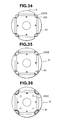
- Figs. 34 to 36 are plan views of other modifications of the rotor core shown in Fig. 31.
- a U-shaped portion between the salient pole portions is filled with a caulking pin for integrally caulking the rotor core 91 and the upper and lower end surface members (not shown) and/or a nonmagnetic filler in place of closing the top portion with the thin bridge 92.
- nonmagnetic caulking pins 100A are passed through the U-shaped notched portion 100 on the outer periphery of the rotor core 91.
- the notched portion 100 in Fig. 34 are filled with nonmagnetic fillers 100B8.
- the notched portions 100 on the outer periphery of the rotor core 91 are f i I-led with the nonmagnetic fillers 100B, and caulking holes 100C for integrally caulking the rotor core 91 and the upper and lower end surface members (not shown) are provided.
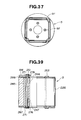
- Fig. 37 is a plan view of a still further modification of the rotor core shown in Fig. 31.
- the rotor core in Fig. 33 is the same as the rotor core 91 shown in Fig. 33 except that the inner peripheral portion of the rotor core 91 is further caulked by caulking pins 97.
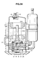
- Fig. 38 is another example of a compressor incorporating a still further embodiment of the rotor of an electric motor according to the present invention.
- the same reference numerals are provided for the element which are the same as those in Fig. 1 and explanation thereof will be omitted.
- Fig. 39 is a partially sectional view of the rotor shown in Fig. 38
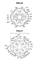
- Fig. 40 is a plan view thereof before the rotary shaft 6 is press-fitted thereinto.
- the reference numeral 226 denotes a rotor core which is composed of a plurality of laminated iron plates 227 each having a thickness of 0.3 to 0,7 mm and punched from an electromagnetic steel plate into a predetermined shape as shown in Fig. 41.
- the iron plates 227 are caulked with each other and integrally laminated.
- the iron plates 227 may be integrally bonded by welding the outer peripheral surfaces.
- the iron plate 227 is punched from an electromagnetic steel plate in to a shape which can form salient pole portions 228 to 231 constituting four magnetic poles, as shown in Fig. 41.
- the reference numerals 232 to 235 denote notched portions between the respective salient pole portions 228 to 231.
- the outer diameter D of the iron plate 277 (the distance between the tops of each pair of salient pole portions) is 40 to 70 mm. In this embodiment, it is 50 mm.
- the reference numerals 241 to 244 denote slots into which later-described magnetic materials 245 (permanent magnets) are press-fitted.
- the slots 241 to 244 are formed in the iron plate 227 on the outer peripheral side thereof on a concentric circle with the rotary shaft 6 in correspondence with the respective salient pole portions 228 to 231.
- the distance d between each of the slots 241 to 244 and the adjacent side wall of the respective salient pole portions 228 to 231 is preferably as small as possible.
- the outer diameter D of the rotor core 226 is set to 40 to 70 mm and the distance d between each of the slots 241 to 244 and the respective salient pole portions 228 to 231 is set to be as small as possible, it is possible to reduce the magnetic flux leakage between the magnetic poles (magnetic materials 245) while maintaining the strength of the rotor core 226, thereby enhancing the operation efficiency of the electric motor 2.
- the reference numeral 246 represents a shaft hole which is formed at the center of the iron plate 227 so as to shrink fit the rotary shaft 6 thereinto.
- the reference numerals 247 to 250 represent through holes formed on the inside of the respective slots 241 to 244 through which later-described caulking rivets 251 to 254, respectively, are passed. Each of the through holes 247 to 250 has appropriate size and shape corresponding to the respective caulking rivets 251 to 254.
- the reference numerals 256 to 259 represent caulking portions for caulking and fixing the iron plates 227 with each other.
- the caulking portions 256 to 259 are provided on an approximately concentric circle with the circle on which the through holes 247 to 250 are provided and between the respective slots 241 to 244.
- the reference numerals 261 to 264 represent holes formed on the inside of the respective caulking portions 256 to 259 so as to form oi passages.
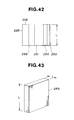
- a plurality of iron plates 227 are laminated and integrally caulked at the caulking portions 256 to 259, thereby producing the rotor core 226 which is shown in the side elevational view in Fig. 42.
- the outerdiam- eter of the rotor core 226 is the outer diameter D (50 mm) of the iron plate 227 and the dimension L of lamination is, for example, 40 mm.
- the ratio L/D of the outer diameter D of the iron plate 227 and the dimension L of lamination is less than 1.1. In this embodiment, the ratio L/D is 0.8. That is, the dimension of the rotor core 226 in the direction of the rotary shaft 6 is set to be a smaller value.
- the magnetic material 245 is composed of a magnet of a rare earth element such as a praseodymium magnet (alloy of praseodymium and iron) and a neodymium magnet (alloy of neodymium and iron) plated with nickel.
- the magnetic material 245 has a rectangular section and takes a shape of a plate as a whole, as shown in Fig. 43.
- the dimension f of the magnetic material 245 in the direction of the rotary shaft 6 is the same as L.
- the size of each of the slots 241 to 244 is determined so that the magnetic material 245 is tightly press-fitted thereinto.
- Fig. 44 shows the demagnetization curve of a ferrite magnet and the demagnetization curve of a rare-earth magnet such as described above which is a permanent magnet used as the magnetic material 245 in Fig. 43.
- the ordinate represents the flux density B and abscissa a coercive force Hc.
- a broken line is a demagnetization curve of a general ferrite magnet and a solid line is a demagnetization curve of a general rare-earth magnet.
- a line T1 represents the values measured at +25 ° C, and a line T2 at +150 ° C.
- the rare-earth magnet has a larger residual flux density Br and a larger coercive force Hc than the ferrite magnet.
- the magnetic energy product of the rare-earth magnet is also very large. It is therefore possible to secure the necessary gap flux and obtain the required output even if the area of the magnet is reduced.
- the rotary shaft 6 is a cantilever type and supported only at the lower part by the bearings 17 and 18, as described above. Therefore, if the dimension of the rotary shaft 6 of the rotor 5 in the axial direction is increased, a large run-out is produced, especially, at the time of high-speed rotation, and with the increase in the vibration and noise, both the reliability and the operation efficiency are lowered.
- the rare-earth magnet is used as the magnetic material 245 provided in the laminated rotor core 226, it is possible to reduce the size of the rotor core 226 while maintaining the necessary output as compared with a conventional rotor core using a ferrite magnet. As a result, it is possible to enhance the reliability and the operation efficiency by reducing the vibration and noise caused by the run-out of the rotor 5.
- the ratio L/D of the outer diameter D and the dimension L of the rotor core 226 in the direction of the rotary shaft 6 is reduced to less than 1.1, in other words, the reduction in the size of the rotor core 226 is realized by the reduction of the dimension of the rotor core 226 in the direction of the rotary shaft 6, it is not necessary to change the facility for producing the compressor, which would be required by a change in the diameter of the rotor core 226 or the outer diameter of the closed container 1 of the compressor.
- the reference numerals 266 and 267 represent flat end surface members which are attached to the upper and lower end of the rotor core 226.
- the end surface members 266 and 267 formed from a nonmagnetic material such as aluminum and a resin material have substantially the same shape as the iron plate 227.
- the outer diameter of the end surface members 266, 267 is smaller than the outer diameter D of the rotor core 226.
- Through holes 271 to 274 are formed in the end surface members 266, 267 at the corresponding positions to the through holes 247 to 250, and a shaft hole 276 and holes 277 to 274 are formed in the end surface members 266, 267 at the corresponding positions to the shaft hole 246 and the holes 261 to 264, as shown in Fig. 40.
- the shaft hole (inner diameter) 276 of the end surface embers 266, 277 is larger than the shaft hole 246 (inner diameter) of the iron plate 227, and the diameter of each of the through holes 271 to 274 of the end surfaces 266, 267 is larger than the diameter of each of the through holes 247 to 250 of the iron plate 227.
- the upper and lower end surface members 266 and 267 are set so as to cover the tops and the bottoms of the slots 241 to 244.
- the through holes 247 to 250 in the iron core 226 and the through holes 271 to 174 in the upper and lower end surface members communicate with each other in the direction of the rotary shaft 6.
- the rivets 251 to 254 are passed through the respective through holes 247 to 250 and 271 to 274 so as to integrally caulk the upper portion and the lower portion of the laminate and produce the rotor 5.
- the rotary shaft 6 is then inserted into the shaft hole 246, and the rotor 5 and the rotary shaft 6 are fixed by shrinkfitting.
- the symbol BW represents a balance weight which is fixed to the rotor core 226 by the rivet 251 together with the upper end surface member 266.
- the outer diameter of the end surface members 266, 267 is smaller than the outer diameter D of the rotor core 226, and the shaft hole 276 (inner diameter) of the end surface members 266, 267 is larger than the shaft hole 246 (inner diameter of the rotor core 226) of the iron plate 227, when the end surface members 266, 267 are attached to the rotor core 226, the end surface members 266, 267 do not protrude to the outside of the rotor core 226 or to the inside of the shaft hole 246 of the rotor core 226.
- each of the through holes 271 to 274 is larger than the diameter of each of the through holes 247 to 250 of the iron plate 227, even if there is a slight error in alignment of the through holes 271 to 274 with the through holes 247 to 250, there is no trouble in inserting the rivets 251 to 254.
- the machining tolerance in each of the outer and inner diameters of the end surface members 266, 267 and the diameter of each of the through holes 271 to 271 may not be very strict. It is also easy to align the inner peripheries, the outer peripheries of the end surface members and the through holes at the time of assembling the end surfaces 266,267 and the rotor core 226.
- FIG. 45 The state of the magnetic field generated within the rotor core 226 by each of the magnetic materials 245 is shown in Fig. 45.
- a substantially concentric magnetic field around the notched portion 233 is generated between the magnetic materials (magnetic poles) 245 which are press-fitted into the adjacent slots 242, 243, for example, as indicated by the broken lines.
- a similar magnetic field is generated between the other adjacent magnetic material 245.
- each of the through holes 247 to 250 as a gap is positioned not at the center but at the peripheral portion of the magnetic paths leading to one magnetic material 245 to the adjacent magnetic material 245. Therefore, the through holes 247 to 250 are unlikely to become a magnetic resistance to the magnetic field produced. It is therefore unlikely to generate a disturbance in the magnetic field, so that it is possible to hold down the deleterious influence of the through holes 247 to 250 on the electric motor 2 to the minimum and increase the output of the electric motor 2.
- the caulking portions 256 to 259 and the holes 261 to 264 of each of the iron plates 227 are disposed between the through holes 247 to 250, it is possible to position the caulking portions 256 to 259 on the outer peripheral side of the rotor core 226, as shown in Fig. 41. It is therefore possible to increase the fixing strength of the iron plates 227 by caulking.
- the caulking portions 256 to 259 and the holes 261 to 264 are situated at the center of the magnetic field, since the caulking portions 256 to 259 and the holes 261 to 164 are minimal gaps as compared with the through holes 247 to 250, the influence thereof on the magnetic field is small.
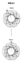
- Figs. 47 to 49 are connection diagrams of the stator coi I 7, and Figs. 50 and 51 are plan views of the stator 4.
- the stator coil 7 disposed around the rotor 5 is a three-phase coil composed of an outer winding of a phase U, an intermediate winding of a phase V and an inner winding of a phase W, each of which constitutes four poles U1 to U4, V1 to V4 and W1 to W4, as shown in Figs. 50 and 51.
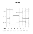
- a direct current is supplied to each of the U-phase winding, the V-phase winding, the W-phase winding of the stator coi I 7 in the order of a pattern 1 to a pattern 6 by a controller (not shown) such as an inverter which is composed of a plurality of switching elements, e.g., transistors, as shown in Fig. 46.
- a controller such as an inverter which is composed of a plurality of switching elements, e.g., transistors, as shown in Fig. 46.
- the distributions of the magnetic fields (synthesized magnetic field) on the inner periphery of the stator 4 generated when the stator coil 7 is excited in the patterns from 1 to 6 are shown in the connection diagrams in Figs. 47 to 49.
- the same pattern number in each drawing refers to the same pattern, and the symbol encircled N in Figs. 50 and 51 corresponds to the symbol encircled N in Figs. 47 to 49.
- the magnetic materials 245 inserted into the slots 241 and 243 are N poles and the magnetic materials 245 inserted into the slots 242 and 244 are S poles, and that the controller excites the stator coil 7 every time the salient pole portions 228 to 231 (magnetic materials 245 therein) of the rotor 5 push each other by the repulsion of the same poles.
- the magnetic field rotates 30 degrees. Accordingly, when the excitation proceeds from the pattern 1 to the pattern 6, the magnetic field rotates 180 degrees, and two periods of synthesized magnetic field exists in 360 degrees, as shown in the connection diagrams in Figs. 47 to 49.
- the rotor 5 is rotated (that is, the rotor 5 also rotates 30 degrees in one pattern) clockwise in Fig. 41, as described above, by the repulsion of the synthesized magnetic field and the magnetic field generated by each magnetic material 245 at a rate at which the voltage and the load applied to the stator coil 7 are balanced (variable in the range of, for example, 500 to 10000 rpm by changing the voltage applied).
- the rotary shaft 6 also rotates with the rotation of the rotor 5, and the eccentric portions 11 and 12 also rotate, so that the first and second rollers 13, 14 rotate, thereby executing the compressing operation.
- the magnetic material 245 and the slots 241 to 244 have a rectangular section in this embodiment, but the section is not restricted thereto and they may have a fan-shaped section of a predetermined width or a segmental section.
- Fig. 52 is a sectional view of a scroll compressor which can adopt each of the above-described embodiments of the rotor of an electric motor according to the present invention.
- the same reference numerals are provided for the element which are the same as those in Figs. 1 and 38, and explanation thereof will be omitted.
- the closed container 1 accommodates an electric motor 2 in the lower part and the compressing element 3 driven by the electric motor 2 in the upper part.
- the electric motor 2 is composed of the stator 4 fixed to the inner wall of the closed container 1 and the rotor 5 supported by the inside of the stator 4 in such a manner as to be freely rotatable around the rotary shaft 6.
- the stator 4 is provided with the stator coil 7.
- the compressing element 3 is composed of a fixed scroll 301 and a rotary scroll 302.
- the fixed scroll 301 is disposed at the highest portion in the container 1 and the peripheral portion thereof is fixed to the closed container 1 by shrink fitting.
- the rotary scroll 201 is opposed to the fixed scroll 301 and a refrigerant compression chamber 303 is formed between the fixed scroll 301 and the rotary scroll 302.
- the rotary scroll 302 rotates with the rotation of the rotary shaft 6 of the electric motor 2.
- the refrigerant sucked from the suction pipe 24 is sucked by the refrigerant compression chamber 303, and as the compression chamber 303 is gradually contracted toward the center with the rotation of the rotary scroll 302, the refrigerant is compressed and discharged from the discharge pipe 22.
- the rotor core 226 of the rotor 5 is composed of a plurality of integrally laminated and caulked iron plates as in the rotor core 226 shown in Fig. 38.
- the upper and lower end surface members 266 and 267 are set so as to cover the tops and the bottoms of the slots.
- the rivets 251 are passed through the respective through holes so as to integrally caulk the upper portion and the lower portion of the laminate and produce the rotor 5.
- the balance weight BW is fixed to the rotor core 226 by the rivet 251 together with the lower end surface member 267.
Landscapes
- Engineering & Computer Science (AREA)
- Power Engineering (AREA)
- Iron Core Of Rotating Electric Machines (AREA)
- Permanent Field Magnets Of Synchronous Machinery (AREA)
- Compressor (AREA)
Abstract
Description
- The present invention relates to the structure of the rotor of an electric motor for a compressor.
- Conventional rotors of electric motors for a compressor generally has the following structures.
- The rotor described in Japanese Patent Laid-Open No. 52359/1982 is produced by inserting a laminated rotor core and magnetic materials into a metal pipe, and integrally die-casting these elements.
- The rotor described in Japanese Patent Laid-Open No. 246748/1990 is produced by inserting a laminated rotor core and magnetic materials into a metal pipe in the same way as in the above-described rotor, and integrally clamping these elements. At the time of clamping, an air gap portion is provided between adjacent magnetic materials so as to safely separate the poles of the magnetic materials, thereby enhancing the efficiency.
- Another rotor is described in Japanese Patent Publication No. 23584/1985. In this rotor, magnetic materials which constitute the magnetic poles are inserted (embedded) into the rotor core. This rotor is used for a synchronous motor which is capable of self starting.
- Japanese Patent Laid-Open No. 185247/1992 discloses another rotor, which is composed of magnetic materials embedded into the salient pole portions of the rotor core which has a salient-pole structure. The rotor core with the magnetic materials embedded therein and end surface members for covering both end surface thereof are arranged, and a rotary shaft is integrally press-fitted into the rotor core in this state.
- The conventional rotors having the above-described structures, however, have problems such as much eddy current loss caused by the cage portion of a die-cast material (e.g., zinc and aluminum), much eddy current loss in a metal pipe, and difficulty in the maintenance of the high dimensional accuracy at the time of production due to the projection provided on the rotor core so as to prevent the movement of the magnetic materials.
- In the rotor provided with air gaps for separating poles, when a breakage such as cracking is produced on the magnetic material (especially, ferrite) due to a thermal shock or a mechanical shock applied to the rotor, the fragments of the magnetic material are flown into the air gaps, which sometimes leads to a further breakage or chipping.
- In some rotors, an eddy current is produced by the secondary conductor in the rotor core, and since part of the magnetic flux produced from the magnetic material is short-circuited in the rotor core (conductor), the operation efficiency of the motor is lowered.
- Other rotors suffer from the problems such as the loosening of the core in the state of the rotor core and difficulty in the maintenance of the high dimensional accuracy due to the low accuracy of assembly in the process of press-fitting the rotary shaft.
- Accordingly, it is an object of the present invention to eliminate the above-described problems in the related art and to provide a rotor of an electric motor for a compressor which can prevent the generation of an eddy current due to a metal protective pipe, the generation of an eddy current in a secondary conductor constituted by a die-cast material, the progress of the breakage of the magnetic material due to air gaps and the lowering of the dimensional accuracy of the rotor.
- To achieve this aim, in a first aspect of the present invention, there is provided a rotor of an electric motor for a compressor having a compressing element and an electric motor for driving the compressing element which are accommodated in a single closed container, the rotor comprising: a rotor core composed of a plurality of laminated iron plates; a first end surface mem- berformed from a nonmagnetic material which has at least a balance weight and a caulking boss for caulking a disk for oil separation and which is disposed at one end of the rotor; a second end surface member formed from a nonmagnetic material which is disposed at the other end of the rotor; and a plurality of caulking members which penetrate the rotor core, the first end surface member and the second end surface member so as to integrally caulk the rotor core, the first end surface member and the second end surface member.
- The rotor core is composed of a plurality of electromagnetic steel plates each having a thickness of not more than 0.5 mm which are integrally laminated by welding or caulking. The first end surface member/and or the second end surface member is composed of a die-cast nonmagnetic metal material, a drawn nonmagnetic metal drawing, or a resin material.
- In a second aspect of the present invention, there is provided a rotor of an electric motor for a compressor having a compressing element and an electric motor for driving the compressing element which are accommodated in a single closed container, the rotor comprising: a rotor core composed of a plurality of laminated iron plates which accommodate a plurality of magnetic materials constituting magnetic poles along the outer periphery of the rotor core; a first end surface member formed from a nonmagnetic material which has at least a balance weight and a caulking boss for caulking a disk for oil separation and which is disposed at one end of the rotor; a second end surface member formed from a nonmagnetic material which is disposed at the other end of the rotor; and a plurality of caulking members which are inserted into the respective through holes formed in the first end surface member and leading to the second end surface member through the rotor core so as to integrally caulk the rotor core, the first end surface member and the second end surface member.
- The rotor core is provided with air gaps between the respective adjacent magnetic poles so as to prevent the short circuit of a magnetic flux. The air gaps lead to the respective through holes in which the caulking members are inserted. The magnetic material is, for example, a magnet of sintered ferrite, a sintered rare earth element, a rare earth element alloy or a plastic containing a rare earth element.
- In a third aspect of the present invention, there is provided a rotor of an electric motor for a compressor having a compressing element and an electric motor for driving the compressing element which are accommodated in a single closed container, the rotor comprising: a rotor core composed of a plurality of laminated iron plates which accommodate a plurality of magnetic materials constituting magnetic poles along the outer periphery of the rotor core; a first end surface member formed from a nonmagnetic material which has at least a balance weight and a caulking boss for caulking a disk for oil separation and which is disposed at one end of the rotor; a second end surface member formed from a nonmagnetic material which is disposed at the other end of the rotor; and a welding portion for integrally welding the outer peripheral surfaces of the rotor core, the first end surface member and the second end surface member.
- In a fourth aspect of the present invention, there is provided a rotor of an electric motor for a compressor having a compressing element and an electric motor for driving the compressing element which are accommodated in a single closed container, the rotor comprising: a rotor core composed of a plurality of laminated iron plates which accommodate a plurality of magnetic materials constituting magnetic poles along the outer periphery of the rotor core; a first end surface member formed from a nonmagnetic material which is disposed at one end of the rotor; a second end surface member formed from a nonmagnetic material which is disposed at the other end of the rotor; and a welding portion for integrally welding the outer peripheral surfaces of the rotor core, the first end surface member and the second end surface member.
- In any of the rotors of an electric motor for a compressor having the above-described structures, since the rotor is integrally produced before the rotor is press-fitted into a rotary shaft, it is possible to maintain the high dimensional accuracy of the rotor.
- In addition, since there is no secondary conductor constituted by a metal pipe or a die-cast material for protection, the generation of an eddy current is prevented.
- The above and other objects, features and advantages of the present invention will become clear from the following description of the preferred embodiments thereof, taken in conjunction with the accompanying drawings.
-
- Fig. 1 is a sectional view of a compressor incorporating an embodiment of the rotor of an electric motor according to the present invention;
- Fig. 2 is a partially sectional view of the embodiment shown in Fig. 1;
- Fig. 3 is a plan view of the first end surface member shown in Fig. 2;
- Fig. 4 is a plan view of the second end surface member shown in Fig. 2;
- Fig. 5 is a plan view of the electromagnetic steel plates (iron plates for the rotor) used for the rotor core shown in Fig. 2;
- Fig. 6 is a plan view of a modification of the rotor core shown in Fig. 2;
- Fig. 7 is a partially sectional view of another embodiment of the rotor of an electric motor for a compressor according to the present invention;
- Fig. 8 is a plan view of the first end surface member shown in Fig. 7;
- Fig. 9 is a plan view of the second end surface member shown in Fig. 7;
- Fig. 10 is a plan view of the electromagnetic steel plates (iron plates for the rotor) used for the rotor core shown in Fig. 7;
- Fig. 11 is a plan view of a modification of the rotor core shown in Fig. 7;
- Fig. 12 is a plan view of another modification of a rotor core shown in Fig. 7;
- Fig. 13 is a partially sectional view of still another embodiment of the rotor of an electric motor for a compressor according to the present invention;
- Fig. 14 is a plan view of the embodiment shown in Fig. 13;
- Fig. 15 is a bottom view of the embodiment shown in Fig. 13;
- Fig. 16 is a plan view of the first end surface member shown in Fig. 13;
- Fig. 17 is a side elevational view of the first end surface member shown in Fig. 13;
- Fig. 18 is a plan view of the second end surface member shown in Fig. 13;
- Fig. 19 is a plan view of the rotor core shown in Fig. 13;
- Fig. 20 is a plan view of a modification of the rotor core shown in Fig. 13;
- Fig. 21 is a plan view of another modification of the rotor core shown in Fig. 13;
- Fig. 22 is a partially sectional view of a further embodiment of the rotor of an electric motor for a compressor according to the present invention;
- Fig. 23 is a partially sectional view of a modification of the rotor core shown in Fig. 22;
- Fig. 24 is a partially sectional view of another modification of the rotor core shown in Fig. 22;
- Fig. 25 is a partially enlarged plan view of sti another modification of the rotor core shown in Fig. 22;
- Fig. 26 is a plan view of a further modification of the rotor core shown in Fig. 22;
- Fig. 27 is a plan view of a still further embodiment of the rotor of an electric motor for a compressor according to the present invention;
- Fig. 28 is a plan view of a modification of the iron plate shown in Fig. 27;
- Fig. 29 is a plan view of another modification of the iron plate shown in Fig. 27;
- Fig. 30 is a plan view of still another modification of the iron plate shown in Fig. 27;
- Fig. 31 is a partially sectional view of a sti further embodiment of the rotor of an electric motor for a compressor according to the present invention;
- Fig. 32 is a plan view of the embodiment shown in Fig. 31;
- Fig. 33 is a plan view of a modification of the rotor core shown in Fig. 31;
- Fig. 34 is a plan view of another modification of the rotor core shown in Fig. 31;
- Fig. 35 is a plan view of still another modification of the rotor core shown in Fig. 31;
- Fig. 36 is a plan view of a further modification of the rotor core shown in Fig. 31;
- Fig. 37 is a plan view of a sti further modification of the rotor core shown in Fig. 31;
- Fig. 38 is another example of a compressor incorporating a still further embodiment of the rotor of an electric motor according to the present invention;
- Fig. 39 is a partially sectional view of the embodiment of the rotor shown in Fig. 38;
- Fig. 40 is a plan view of the embodiment shown in Fig. 39;
- Fig. 41 is a plan view of the electromagnetic steel plates (iron plates for the rotor) used for the rotor core shown in Fig. 39;
- Fig. 42 is a side elevational view of the rotor core which is incorporated into the embodiment shown in Fig, 39;
- Fig. 43 is a perspective view of a magnetic material which is incorporated into the embodiment shown in Fig. 39;
- Fig. 44 shows the demagnetization curves of the permanent magnet used as the magnetic material in Fig. 43 as compared with the demagnetization curves of a ferrite magnet;
- Fig. 45 is a plan view of the rotor core shown in Fig. 42, explaining the magnetic field generated by the magnetic materials;
- Fig. 46 is a timing chart of the excitation patterns of the stator coil in the compressor shown in Fig. 38;
- Fig. 47 shows the connection diagrams of the stator coil showing the distribution of the magnetic field on the inner periphery of the stator in the
patterns 1 to 2 in Fig. 46; - Fig. 48 shows the connection diagrams of the stator coil showing the distribution of the magnetic field on the inner periphery of the stator in the
patterns 3 to 4 in Fig. 46; - Fig. 49 shows the connection diagrams of the stator coil showing the distribution of the magnetic field on the inner periphery of the stator in the
patterns 5 to 6 in Fig. 46; - Fig. 50 is a plan view of the stator showing the distribution of the magnetic field on the inner periphery of the stator in each of the
patterns 1 to 4 in Fig. 46; - Fig. 51 is a plan view of the stator showing the distribution of the magnetic field on the inner periphery of the stator in each of the
patterns 5 to 6 in Fig. 46; and - Fig. 52 is a sectional view of still another example of a compressor incorporating the rotor of an electric motor according to the present invention.
- The present invention will be explained in more detail with reference to the following drawings. Fig. 1 is a sectional view of a rotary compressor. In Fig. 1, the
reference numeral 1 represents a closed container accommodating anelectric motor 2 in the upper part and acompressing element 3 driven by theelectric motor 2 in the lower part. Theclosed container 1 is produced by bonding and closing the container accommodating theelectric motor 2 and a container accommodating the compressing element by high- fequency welding or the like. - The
electric motor 2 is composed of astator 4 fixed to the inner wall of theclosed container 1 and arotor 5 supported by the inside of thestator 4 in such a manner as to be freely rotatable around arotary shaft 6. Thestator 4 is provided with astator coil 7 for providing therotor 5 with a rotating magnetic flux . - The compressing
element 3 is provided with a firstrotary cylinder 9 and asecond rotary cylinder 10 which are separated from each other by apartition plate 8.Eccentric portions cylinders rotary shaft 6 with a phase difference of 180 degrees therebetween. - The reference numerals 13 and 14 represent first and second rollers which rotate in the
cylinders eccentric portions -
Afirst frame 15 and thepartition plate 8 sandwich thecylinder 9 therebetween, and asecond frame 16 and thepartition plate 8 sandwich thecylinder 10 therebetween, thereby forming the respective compression spaces. Thefirst frame 15 and thesecond frame 16 are provided with bearingportions rotary shaft 6. -
Discharge mufflers first frame 15 and thesecond frame 16, respectively, in such a manner as to cover therespective frames cylinder 9 and thedischarge muffler 19 communicate with each other through a discharge hole (not shown) formed in thefirst frame 15, and thecylinder 10 and thedischarge muffler 20 communicate with each other through a discharge hole (not shown) formed in thesecond frame 16. Abypass pipe 21 provided on the outside of theclosed container 1 communicates with thedischarge muffler 20. - The
reference numeral 22 denotes a discharge pipe provided at the top of theclosed container cylinders terminal 25 supplies electric power from an external equipment to thecoil 7 of the stator4. (Lead wires for connecting thestator coil 7 and the closingterminal 25 are not shown). Thereference numeral 26 represents an oil separation disk which is fixed to therotary shaft 6 by abolt 27. Thedisk 26 may be fixed by a later-described boss. - Fig. 2 is a partially sectional view of the
rotor 5 shown in Fig. 1 before therotary shaft 6 is press-fitted thereinto. Arotor core 28 is composed of a plurality of laminated electromagnetic steel plates (iron plates for a rotor) each having a thickness of 0.5 mm and punched into a predetermined shape. The electromagnetic steel plates are caulked with each other and integrally laminated (or integrally welded). - The
reference numeral 29 denotes a magnetic material such as a magnet of sintered ferrite, a sintered rare earth element, an alloy of rare earth element and iron, and a plastic containing a rare earth element. As examples of the rare earth element praseodymium and neodymium will be cited. Themagnetic material 29 is press-fitted or inserted into a slot which is formed in therotor core 28 in the axial direction. A plurality ofmagnetic materials 29 are disposed in therotor core 28 along the outer periphery of therotor core 28. - A first
end surface member 30 which is attached to one end of therotor core 28 hasbalance weights element 3, andbosses balance weights end surface member 30, thebalance weights 33 to 36 and thebosses - The positions and the shapes of the
bosses I separation disk 26. - A second
end surface member 38 which is attached to the other end of therotor core 28 is integrally formed into an annular shape from a nonmagnetic material such as aluminum by die-casting or drawing or from a synthetic resin material in the same way as in the firstend surface member 30. - A plurality of
welding portions 37 are provided on the outer periphery of therotor 5 in the axial direction. After themagnetic materials 29 are press-fitted into therotor core 28 and the firstend surface member 30 and the secondend surface member 38 are set, thesewelding portions 37 are simultaneously welded so as to produce therotor 5. - Fig. 3 is a plan view of the first
end surface member 30 shown in Fig. 2. Theend surface member 30 has a concentric (annular) shape, and therotary shaft 6 of therotor 5 is passed through ashaft hole 39. - Fig. 4 is a plan view of the second
end surface member 38 shown in Fig. 2. Theend surface member 38 has a concentric (annular) shape, and therotary shaft 6 of therotor 5 is passed through ashaft hole 40. - Fig. 5 is a plan view of the electromagnetic steel plates (iron plates for the rotor) used for the
rotor core 28 shown in Fig. 2. In Fig. 5, thereference numerals 41 to 44 denote slots into which themagnetic materials 29 having a section having a figure obtained by removing a small sector from a concentric large sector (this section will be hereinunder referred to as "a fan-shaped section") are press-fitted. Theslots 41 to 44 are formed in therotor core 28 along the outer periphery.Slits 45 to 48 are provided between the respectiveadjacent slots 41 to 44 (on the boundaries between the poles). Theslits 45 to 48 function as the air gaps for promoting the separation of the respective magnetic poles after themagnetic materials 29 are press-fitted into theslots 41 to 44. - Fig. 6 is a plan view of a modification of the
rotor core 28 shown in Fig. 2. The rotor core shown in Fig. 6 is composed of a plurality of laminatedelectromagnetic steel plates 50 each punched into a shape for formingsalient pole portions 51 to 54. The reference numerals 55 to 58 denote notched portions for forming thesalient pole portions 51 to 54. - The reference numerals 59 to 62 denote slots into which the
magnetic materials 29 are press-fitted, and 63 a shaft hole through which therotary shaft 6 is passed. - After the
magnetic materials 29 are press-fitted into the rotor core, theend surface members rotor 5 is welded so as to integrally form therotor 5 in the same way as therotor 5 shown in Fig. 2. In this example, each of theend surface members - Fig. 7 is a partially sectional view of another embodiment of the rotor of an electric motor for a compressor according to the present invention. In Fig. 7, the
reference numeral 101 denotes a rotor core which is composed of a plurality of laminated electromagnetic steel plates (iron plates for a rotor) each having a thickness of 0.5 mm and punched into a predetermined shape. The electromagnetic steel plates are caulked with each other and integrally laminated (or integrally welded). - The
reference numeral 102 denotes a magnetic material (the same as the magnetic material shown in Fig. 2). Themagnetic material 102 is press-fitted or inserted into a slot which is formed in therotor core 28 in the axial direction. A plurality ofmagnetic materials 102 are disposed in therotor core 101 along the outer periphery of therotor core 101. - Afirst
end surface member 103 which is attached to one end of therotor core 101 hasbalance weights element 3, andbosses balance weights end surface member 103, thebalance weights 104 to 107 and thebosses - The positions and the shapes of the
bosses oil separation disk 26. - A second
end surface member 110 which is attached to the other end of therotor core 101 is integrally formed into an annular shape from a nonmagnetic material such as aluminum by die-casting or drawing orfrom a synthetic resin material in the same way as in the firstend surface member 103. - Caulking members (caulking pins, caulking bolts orthe like) 111 to 114 integrally caulk the first
end surface member 103, therotor core 101 and the secondend surface member 110 by utilizing the through holes formed in the firstend surface member 103, therotor core 101 and the secondend surface member 110. - Fig. 8 is a plan view of the first
end surface member 103 shown in Fig. 7. Theend surface member 103 has a concentric (annular) shape, and therotary shaft 6 of therotor 5 is passed through ashaft hole 119. - The
reference numerals 115 to 118 represent through holes through which the caulking members 111 to 114, respectively, are passed. Each of the throughholes 115 to 118 has appropriate size and shape corresponding to the respective caulking members 111 to 114. - Fig. 9 is a plan view of the second
end surface member 110 shown in Fig. 7. Theend surface member 110 has a concentric (annular) shape, and therotary shaft 6 of therotor 5 is passed through ashaft hole 124. - The
reference numerals 120 to 123 represent through holes through which the caulking members 111 to 114, respectively, are passed. Each of the throughholes 120 to 123 has appropriate size and shape corresponding to the respective caulking members 111 to 114. - Fig. 10 is a plan view of the electromagnetic steel plates (iron plates for the rotor) used for the
rotor core 101 shown in Fig. 7. In Fig. 10, thereference numerals 125 to 128 denote slots into which themagnetic materials 102 having a fan-shaped section are press-fitted. Theslots 125 to 128 are formed in therotor core 101 along the outer periphery.Slits 129 to 132 are provided between the respectiveadjacent slots 125 to 128 (on the boundaries between the poles). Theslits 129 to 132 function as air gaps for promoting the separation of the respective magnetic poles after themagnetic materials 102 are press-fitted into theslots 125 to 128. - The
reference numerals 131 to 134 represent through holes through which the caulking members 111 to 114, respectively, are passed. Each of the throughholes 120 to 123 has appropriate size and shape corresponding to the respective caulking members 111 to 114. They are disposed between the respectiveadjacent slots 125 to 128 so as to communicate with therespective slits 129 to 132. Since theslits 129 to 132 communicate with the throughholes 131 to 134, the air gaps between the adjacent magnetic poles are so enlarged as to reduce the flux leakage and the operation efficiency of the electric motor is enhanced to that degree. Thereference numeral 135 represents a shaft hole into which therotary shaft 6 is press-fitted. - After the first
end surface member 103, therotor core 101 and the secondend surface member 110 are laid with one on top of another in such a manner that the throughholes 115 to 118, 131 to 134 and 120 to 123 communicate with each other, they are integrally caulked by the caulking members 111 to 114 so as to produce therotor 5. - Fig. 11 is a plan view of a modification of the
rotor core 101 shown in Fig. 7. The rotor core shown in Fig. 11 is composed of a plurality of laminatedelectromagnetic steel plates 140 each punched into a shape for formingsalient pole portions 136 to 139. Thereference numerals 141 to 144 denote notched portions for forming thesalient pole portions 136 to 139. - The
reference numerals 145 to 148 denote slots into which themagnetic materials 102 are press-fitted and 149 a shaft hole through which therotary shaft 6 is passed. - The
reference numerals 150 to 153 represent through holes through which the caulking members 111 to 114, respectively, are passed. Each of the throughholes 150 to 153 has appropriate size and shape corresponding to the respective caulking members 111 to 114. After themagnetic materials 102 are press-fitted into the rotor core, the end surface members are set, and therotor 5 is integrally produced by using the caulking members 111 to 114, in the same way as therotor 5 shown in Fig. 7. In this example, each of the end surface members may have the same shape as the respective end surfaces of the rotor cores. - Fig. 12 is a plan view of another modification of the
rotor core 101 shown in Fig. 7. In Fig. 12, thereference numerals 154 to 157 denote slots into which themagnetic materials 102 having a fan-shaped section are press-fitted and 158 to 161 slits provided between the respectiveadjacent slots 154 to 157 (on the boundaries between the poles). Theslits 158 to 161 function as air gaps for promoting the separation of the respective magnetic poles after themagnetic materials 102 are press-fitted into theslots 154 to 157. - The
reference numerals 162 to 165 represent through holes through which the caulking members 111 to 114, respectively, are passed. Each of the throughholes 162 to 165 has appropriate size and shape corresponding to the respective caulking members 111 to 114. They are disposed between the respectiveadjacent slots 154 to 157 so as to communicate with therespective slits 158 to 161. These continuous holes and slits open on the outer periphery of the rotor core. - Since the
slits 158 to 161 communicate with the throughholes 162 to 165 and these continuous holes open on the outer periphery of the rotor core, the air gaps between the adjacent magnetic poles are so enlarged as to reduce the flux leakage and the operation efficiency of the electric motor is enhanced to that degree. Thereference numeral 166 represents a shaft hole into which therotary shaft 6 is press-fitted. - As described above, in the embodiments shown in Figs. 1 to 12, since there is no secondary conductor constituted by a metal pipe or a die-cast material which causes an eddy current, it is possible to enhance the operation efficiency of the electric motor to that degree. In other words, a smaller motor than a conventional one can have the same output. It is therefore possible to reduce the entire size of a compressor.
- In addition, by providing air gaps between the respective adjacent magnetic poles of the rotor, it is possible to reduce the flux leakage and to further enhance the operation efficiency of the electric motor.
- Fig. 13 is a partially sectional view of sti another embodiment of the
rotor 5 of an electric motor for a compressor according to the present invention, Fig. 14 is a plan view thereof and Fig. 15 is a bottom view thereof. Fig. 16 is a plan view of the first end surface member of the rotor, Fig. 17 is a side elevational view thereof, Fig. 18 is a plan view of the second end surface member of the rotor and Fig. 19 is a plan view of the rotor core shown in Fig. 13. In these drawings, thereference numeral 69 represents a rotor core and 70 a magnetic material composed of a permanent magnet and inserted into therotor core 69. A firstend surface member 67 and a secondend surface member 68 formed from a nonmagnetic material similar to that in the above-described embodiments are disposed on the top and the bottom of therotor core 67 and themagnetic materials 70. These elements are bolted by a plurality of (four in this embodiment)bolts 71 andnuts 72, and therotary shaft 6 of theelectric motor 2 is press-fitted thereinto. - In this case, the inner diameter dl of each of the first and second
end surface members rotor core 69 shown in Fig. 19, and the outer diameter D1 of each of the first and secondend surface members rotor core 69. The diameter of each of the bolt holes 67a and 68a formed in the first and secondend surface members bolt hole 69a of therotor core 69 shown in Fig. 19. - In Fig. 19, the
rotor core 69 has fourslits 69b and and fourslots 69c having a fan-shaped section into whichmagnetic materials 70 having a fan-shaped section are press-fitted. - Fig. 20 shows a modification of the
rotor core 69 shown in Fig. 13. In arotor core 73 shown in Fig. 20, bolt holes 73a communicate withslits 73b and these continuous holes open on the outer periphery of therotor core 73. Thereference numeral 73c denotes a through hole for inserting themagnetic material 70 thereinto. - Fig. 21 shows another modification of the
rotor core 69 shown in Fig. 13. Arotor core 74 shown in Fig. 21 hasbolt holes 74a andslots 74c for inserting the plate-likemagnetic materials 70 thereinto. - According to the embodiment shown in Figs. 13 to 21, the machining tolerance in each of the outer and inner diameters of the first and second
end surface members - Fig. 22 is a partially sectional view of a further embodiment of the rotor of an electric motor for a compressor according to the present invention. In this embodiment, the rotor is provided with grooves having a U-shaped section in the walls of the slots of the rotor core perpendicularly relative to the axial direction of the slots.
Grooves slot 79 of arotor core 76. Thereference numeral 77 denotes a magnetic material (permanent magnet) press-fitted into eachslot 79. In the modification of therotor core 76 shown in Fig. 23, one groove 80c is added at the central portion of eachslot 79, and in the modification of therotor core 76 shown in Fig. 24, twogrooves 80d are added at the central portion of eachslot 79. - In any of these
rotor cores 76, when themagnetic materials 77 are press-fitted into theslots 79, therotor core 76 which receives the pressure deforms so as to release the pressure, thereby reducing the resistance to press-fit. - Fig. 25 is a partially enlarged plan view of sti another modification of the
rotor core 76 shown in Fig. 22. The rotor core shown in Fig. 25 is provided in the axial direction of theslots 79 with grooves having a V-shaped section on each of the inner walls of theslots 79. - One
groove 81 having a V-shaped section is provided in each opposing sideinner walls grooves 81 are provided in opposing peripheralinner walls slot 79. - When the
magnetic materials 77 are press-fitted into theslots 79, thegrooves 81 deform so as to elastically hold themagnetic materials 77. - Such grooves can also be provided in the rotor core shown in Fig. 26, in which
magnetic material 77a has a plate-like shape. - According to the embodiment shown in Figs. 22 to 26, even if a magnet of a sintered material such as ferrite is used as the magnetic material, since no additional machining is necessary, it is possible to allow a large press-fit margin and the engagement between the magnetic material and the slot is firm, so that it is possible to simplify the production steps, which leads to a large reduction in the cost.
- Fig. 27 is a plan view of an iron plate constituting a still further embodiment of the rotor of an electric motor for a compressor according to the present invention. An
iron plate 82 is provided withslots 84A to 84D having a fan-shaped section into which magnetic materials (permanent magnets)83Ato 83D are press-fitted. Theslots 84A to 84D are formed in theiron plate 82 along the outer periphery. Since therotor 5 is used for a quadripolar electric motor, the four magnetic materials are used.Slits magnetic materials magnetic material slits - As the
magnetic materials 83A to 83D, magnets of sintered ferrite, a sintered rare earth element, an alloy of rare earth element and iron and a plastic containing a rare earth element are usable, as described above. Therotary shaft 6 is press-fitted into therotor 5 through ashaft hole 86 shown in Fig. 1 by shrink fitting or the like. A caulking rod (not shown) is inserted into a circular portion at the proximal end of each of theslits 85Aand 85C so as to integrally assemble and laminate a multiplicity ofiron plates 82. - According to this structure, since the
slits magnetic materials magnetic material magnetic materials magnetic material - Fig. 28 is a plan view of a modification of the
iron plate 82 shown in Fig. 27. In this case,slots iron plate 82, and twomagnetic materials slots - Fig. 29 is a plan view of another modification of the
iron plate 82 shown in Fig. 27. In this case,linear slots 87Ato 87D are provided in theiron plate 82, and plate-likemagnetic materials 88A to 88A are press-fitted into therespective slots 87A to 87D. Since therotor 5 is used for a quadripolar electric motor, the four magnetic materials are used. Two notchedportions magnetic materials magnetic materials - These notched
portions reference numeral 90 denotes a hole into which a caulking rod (not shown) for integrally assembling and laminating a multiplicity ofiron plates 82 is inserted. - According to this structure, the short circuit of the magnetic flux is prevented between the
magnetic materials magnetic materials portions magnetic materials magnetic materials - Fig. 30 is a plan view of still another modification of the
iron plate 82 shown in Fig. 27. In this case, four notchedportions 89A to 89D are provided, while only twomagnetic materials magnetic materials portions 89A to 89D exert no influence on the magnetic flux. That is, the rotor is for a bipolar motor. - In the embodiment shown in Figs. 27 to 30, a method of converting a quadripolar motor structure to a bipolar motor structure is described. It goes without saying that this embodiment is applicable to the case of reducing, for example, the eight poles of a motor to four poles.
- In other words, a comparatively simple structure of providing a means for preventing the short circuit of the magnetic flux between one pair of magnetic poles and not providing the means at the other ends of the respective poles can easily reduce the number of poles of an electric motor.
- As a result, for example, it is possible to reduce the chopping frequency of the electric power which is supplied to the stator coil to 1/2 by changing a bipolar motor to a quadripolar motor. Therefore, a chopper transistor used in an inverter circuit need not be an expensive transistor having a high switching response characteristic. In addition, since the loss in a switching circuit is reduced, the enhancement of the inversion efficiency of an inverter and the motor efficiency is achieved.
- Fig. 31 is a partially sectional view of a sti further embodiment of the rotor of an electric motor for a compressor according to the present invention, and Fig. 32 is a plan view thereof.
- A
rotor core 91 incorporating therotor 5 is composed of a plurality of laminated iron plates. AU-shapedspace 93 with the top portion closed by athin bridge 92 is formed in each iron plate between adjacent salient pole portions. - The
reference numeral 94 represents a first end surface member attached to one end of therotor core 91, and 95 a second end surface member attached to the other end of therotor core 91. Thereference numeral 96 denotes a magnetic material composed of a permanent magnet. - According to this structure, although the
rotor 5 has a salient pole structure, since there is no notched portion on the outer periphery, in the case of rotating the motor in a liquid as an electric motor for a compressor, the rotation resistance is reduced to a minimum. Since the notched portion (space 93) is connected by thethin bridge 92, the magnetic short circuit between the poles is negligible. - Fig. 33 is a plan view of a modification of the rotor core shown in Fig. 31. A top-closed
U-shaped space 98 similar to thespace 93 is formed, and acaulking pin 99 of a nonmagnetic material for integrally bonding therotor core 91 and the upper and lower end surface members (not shown) is passed through thespace 98. - According to this structure, since the
caulking pin 99 is inserted into thespace 98, a through hole for passing a caulking pin therethrough is obviated, and the magnetic resistance and the core loss at this portion are reduced, thereby enabling the increase in the efficiency of the motor. - Figs. 34 to 36 are plan views of other modifications of the rotor core shown in Fig. 31. In each of these rotor cores, a U-shaped portion between the salient pole portions is filled with a caulking pin for integrally caulking the
rotor core 91 and the upper and lower end surface members (not shown) and/or a nonmagnetic filler in place of closing the top portion with thethin bridge 92. - In Fig. 34, nonmagnetic caulking pins 100A are passed through the U-shaped notched
portion 100 on the outer periphery of therotor core 91. In Fig. 35, the notchedportion 100 in Fig. 34 are filled with nonmagnetic fillers 100B8. In Fig. 36, the notchedportions 100 on the outer periphery of therotor core 91 are f i I-led with the nonmagnetic fillers 100B, andcaulking holes 100C for integrally caulking therotor core 91 and the upper and lower end surface members (not shown) are provided. - Fig. 37 is a plan view of a still further modification of the rotor core shown in Fig. 31. The rotor core in Fig. 33 is the same as the
rotor core 91 shown in Fig. 33 except that the inner peripheral portion of therotor core 91 is further caulked by caulking pins 97. - According to these structures shown in Fig. 32 to 37, since the U-shaped portion is filled with a nonmagnetic caulking pin for integrally caulking the rotor core and the upper and lower end surface members and/or a nonmagnetic fitter in place of closing the top portion with the thin bridge, a through hole for passing a caulking pin therethrough is obviated, and the magnetic resistance and the core loss at this portion are reduced, thereby enabling the increase in the efficiency of the motor.
- Fig. 38 is another example of a compressor incorporating a still further embodiment of the rotor of an electric motor according to the present invention. The same reference numerals are provided for the element which are the same as those in Fig. 1 and explanation thereof will be omitted.
- Fig. 39 is a partially sectional view of the rotor shown in Fig. 38, and Fig. 40 is a plan view thereof before the
rotary shaft 6 is press-fitted thereinto. In each of the drawings, thereference numeral 226 denotes a rotor core which is composed of a plurality oflaminated iron plates 227 each having a thickness of 0.3 to 0,7 mm and punched from an electromagnetic steel plate into a predetermined shape as shown in Fig. 41. Theiron plates 227 are caulked with each other and integrally laminated. Alternatively, theiron plates 227 may be integrally bonded by welding the outer peripheral surfaces. - The
iron plate 227 is punched from an electromagnetic steel plate in to a shape which can formsalient pole portions 228 to 231 constituting four magnetic poles, as shown in Fig. 41. Thereference numerals 232 to 235 denote notched portions between the respectivesalient pole portions 228 to 231. - The outer diameter D of the iron plate 277 (the distance between the tops of each pair of salient pole portions) is 40 to 70 mm. In this embodiment, it is 50 mm.
- The
reference numerals 241 to 244 denote slots into which later-described magnetic materials 245 (permanent magnets) are press-fitted. Theslots 241 to 244 are formed in theiron plate 227 on the outer peripheral side thereof on a concentric circle with therotary shaft 6 in correspondence with the respectivesalient pole portions 228 to 231. The distance d between each of theslots 241 to 244 and the adjacent side wall of the respectivesalient pole portions 228 to 231 is preferably as small as possible. - In this way, since the outer diameter D of the
rotor core 226 is set to 40 to 70 mm and the distance d between each of theslots 241 to 244 and the respectivesalient pole portions 228 to 231 is set to be as small as possible, it is possible to reduce the magnetic flux leakage between the magnetic poles (magnetic materials 245) while maintaining the strength of therotor core 226, thereby enhancing the operation efficiency of theelectric motor 2. - The
reference numeral 246 represents a shaft hole which is formed at the center of theiron plate 227 so as to shrink fit therotary shaft 6 thereinto. Thereference numerals 247 to 250 represent through holes formed on the inside of therespective slots 241 to 244 through which later-describedcaulking rivets 251 to 254, respectively, are passed. Each of the throughholes 247 to 250 has appropriate size and shape corresponding to therespective caulking rivets 251 to 254. Thereference numerals 256 to 259 represent caulking portions for caulking and fixing theiron plates 227 with each other. Thecaulking portions 256 to 259 are provided on an approximately concentric circle with the circle on which the throughholes 247 to 250 are provided and between therespective slots 241 to 244. Thereference numerals 261 to 264 represent holes formed on the inside of therespective caulking portions 256 to 259 so as to form oi passages. - A plurality of
iron plates 227 are laminated and integrally caulked at thecaulking portions 256 to 259, thereby producing therotor core 226 which is shown in the side elevational view in Fig. 42. The outerdiam- eter of therotor core 226 is the outer diameter D (50 mm) of theiron plate 227 and the dimension L of lamination is, for example, 40 mm. The ratio L/D of the outer diameter D of theiron plate 227 and the dimension L of lamination is less than 1.1. In this embodiment, the ratio L/D is 0.8. That is, the dimension of therotor core 226 in the direction of therotary shaft 6 is set to be a smaller value. - The
magnetic material 245 is composed of a magnet of a rare earth element such as a praseodymium magnet (alloy of praseodymium and iron) and a neodymium magnet (alloy of neodymium and iron) plated with nickel. Themagnetic material 245 has a rectangular section and takes a shape of a plate as a whole, as shown in Fig. 43. The dimension f of themagnetic material 245 in the direction of therotary shaft 6 is the same as L. The size of each of theslots 241 to 244 is determined so that themagnetic material 245 is tightly press-fitted thereinto. - Fig. 44 shows the demagnetization curve of a ferrite magnet and the demagnetization curve of a rare-earth magnet such as described above which is a permanent magnet used as the
magnetic material 245 in Fig. 43. The ordinate represents the flux density B and abscissa a coercive force Hc. A broken line is a demagnetization curve of a general ferrite magnet and a solid line is a demagnetization curve of a general rare-earth magnet. A line T1 represents the values measured at +25°C, and a line T2 at +150°C. - As is clear from Fig. 44, the rare-earth magnet has a larger residual flux density Br and a larger coercive force Hc than the ferrite magnet. The magnetic energy product of the rare-earth magnet is also very large. It is therefore possible to secure the necessary gap flux and obtain the required output even if the area of the magnet is reduced.
- The
rotary shaft 6 is a cantilever type and supported only at the lower part by thebearings rotary shaft 6 of therotor 5 in the axial direction is increased, a large run-out is produced, especially, at the time of high-speed rotation, and with the increase in the vibration and noise, both the reliability and the operation efficiency are lowered. - In this embodiment, however, since the rare-earth magnet is used as the
magnetic material 245 provided in thelaminated rotor core 226, it is possible to reduce the size of therotor core 226 while maintaining the necessary output as compared with a conventional rotor core using a ferrite magnet. As a result, it is possible to enhance the reliability and the operation efficiency by reducing the vibration and noise caused by the run-out of therotor 5. - Especially, since the ratio L/D of the outer diameter D and the dimension L of the
rotor core 226 in the direction of therotary shaft 6 is reduced to less than 1.1, in other words, the reduction in the size of therotor core 226 is realized by the reduction of the dimension of therotor core 226 in the direction of therotary shaft 6, it is not necessary to change the facility for producing the compressor, which would be required by a change in the diameter of therotor core 226 or the outer diameter of theclosed container 1 of the compressor. - Referring to Fig. 38 again, the
reference numerals rotor core 226. Theend surface members iron plate 227. The outer diameter of theend surface members rotor core 226. Throughholes 271 to 274 are formed in theend surface members holes 247 to 250, and ashaft hole 276 andholes 277 to 274 are formed in theend surface members shaft hole 246 and theholes 261 to 264, as shown in Fig. 40. - The shaft hole (inner diameter) 276 of the
end surface embers iron plate 227, and the diameter of each of the throughholes 271 to 274 of the end surfaces 266, 267 is larger than the diameter of each of the throughholes 247 to 250 of theiron plate 227. - After the
magnetic materials 245 are press-fitted into theslots 241 to 244 of therotor core 226, the upper and lowerend surface members slots 241 to 244. In this state, the throughholes 247 to 250 in theiron core 226 and the throughholes 271 to 174 in the upper and lower end surface members communicate with each other in the direction of therotary shaft 6. Thereafter, therivets 251 to 254 are passed through the respective throughholes 247 to 250 and 271 to 274 so as to integrally caulk the upper portion and the lower portion of the laminate and produce therotor 5. Therotary shaft 6 is then inserted into theshaft hole 246, and therotor 5 and therotary shaft 6 are fixed by shrinkfitting. The symbol BW represents a balance weight which is fixed to therotor core 226 by therivet 251 together with the upperend surface member 266. - In this manner, since the
rotor 5 is integrally assembled before therotary shaft 6 is press-fitted theretinto, it is possible to maintain the high dimensional accuracy of therotor 5. In addition, since theend surface members rotor core 226, there is no secondary conductor constituted by a metal pipe or a die-cast material, thereby preventing the generation of an eddy current caused thereby. - Furthermore, since the outer diameter of the
end surface members rotor core 226, and the shaft hole 276 (inner diameter) of theend surface members iron plate 227, when theend surface members rotor core 226, theend surface members rotor core 226 or to the inside of theshaft hole 246 of therotor core 226. - In addition, since the diameter of each of the through
holes 271 to 274 is larger than the diameter of each of the throughholes 247 to 250 of theiron plate 227, even if there is a slight error in alignment of the throughholes 271 to 274 with the throughholes 247 to 250, there is no trouble in inserting therivets 251 to 254. - Therefore, the machining tolerance in each of the outer and inner diameters of the
end surface members holes 271 to 271 may not be very strict. It is also easy to align the inner peripheries, the outer peripheries of the end surface members and the through holes at the time of assembling the end surfaces 266,267 and therotor core 226. - The state of the magnetic field generated within the
rotor core 226 by each of themagnetic materials 245 is shown in Fig. 45. A substantially concentric magnetic field around the notchedportion 233 is generated between the magnetic materials (magnetic poles) 245 which are press-fitted into theadjacent slots magnetic material 245. - Since the through
holes 247 to 250 are formed in correspondence with the inner walls of the respectivemagnetic materials 245, each of the throughholes 247 to 250 as a gap is positioned not at the center but at the peripheral portion of the magnetic paths leading to onemagnetic material 245 to the adjacentmagnetic material 245. Therefore, the throughholes 247 to 250 are unlikely to become a magnetic resistance to the magnetic field produced. It is therefore unlikely to generate a disturbance in the magnetic field, so that it is possible to hold down the deleterious influence of the throughholes 247 to 250 on theelectric motor 2 to the minimum and increase the output of theelectric motor 2. - Since the
caulking portions 256 to 259 and theholes 261 to 264 of each of theiron plates 227 are disposed between the throughholes 247 to 250, it is possible to position thecaulking portions 256 to 259 on the outer peripheral side of therotor core 226, as shown in Fig. 41. It is therefore possible to increase the fixing strength of theiron plates 227 by caulking. Although thecaulking portions 256 to 259 and theholes 261 to 264 are situated at the center of the magnetic field, since thecaulking portions 256 to 259 and theholes 261 to 164 are minimal gaps as compared with the throughholes 247 to 250, the influence thereof on the magnetic field is small. - The operation of the
electric motor 2 in this embodiment will now be explained with reference to Figs. 46 to 51. Figs. 47 to 49 are connection diagrams of the stator coi I 7, and Figs. 50 and 51 are plan views of thestator 4. Thestator coil 7 disposed around therotor 5 is a three-phase coil composed of an outer winding of a phase U, an intermediate winding of a phase V and an inner winding of a phase W, each of which constitutes four poles U1 to U4, V1 to V4 and W1 to W4, as shown in Figs. 50 and 51. - A direct current is supplied to each of the U-phase winding, the V-phase winding, the W-phase winding of the stator coi I 7 in the order of a
pattern 1 to apattern 6 by a controller (not shown) such as an inverter which is composed of a plurality of switching elements, e.g., transistors, as shown in Fig. 46. The distributions of the magnetic fields (synthesized magnetic field) on the inner periphery of thestator 4 generated when thestator coil 7 is excited in the patterns from 1 to 6 are shown in the connection diagrams in Figs. 47 to 49. - The same pattern number in each drawing refers to the same pattern, and the symbol encircled N in Figs. 50 and 51 corresponds to the symbol encircled N in Figs. 47 to 49. In this embodiment, it is assumed that the
magnetic materials 245 inserted into theslots magnetic materials 245 inserted into theslots stator coil 7 every time thesalient pole portions 228 to 231 (magnetic materials 245 therein) of therotor 5 push each other by the repulsion of the same poles. - When the
pattern 1 is shifted to thepattern 2, the magnetic field rotates 30 degrees. Accordingly, when the excitation proceeds from thepattern 1 to thepattern 6, the magnetic field rotates 180 degrees, and two periods of synthesized magnetic field exists in 360 degrees, as shown in the connection diagrams in Figs. 47 to 49. Therotor 5 is rotated (that is, therotor 5 also rotates 30 degrees in one pattern) clockwise in Fig. 41, as described above, by the repulsion of the synthesized magnetic field and the magnetic field generated by eachmagnetic material 245 at a rate at which the voltage and the load applied to thestator coil 7 are balanced (variable in the range of, for example, 500 to 10000 rpm by changing the voltage applied). Therotary shaft 6 also rotates with the rotation of therotor 5, and theeccentric portions second rollers - Although the
magnetic material 245 and theslots 241 to 244 have a rectangular section in this embodiment, but the section is not restricted thereto and they may have a fan-shaped section of a predetermined width or a segmental section. - The above-described embodiments of the rotor are applied to the electric motorfora a rotary compressor, but the application of the rotor of the present invention is not restricted thereto. The rotor of an electric motor of the present invention is also effective for a scroll compressor such as that shown in Fig. 52. Fig. 52 is a sectional view of a scroll compressor which can adopt each of the above-described embodiments of the rotor of an electric motor according to the present invention. The same reference numerals are provided for the element which are the same as those in Figs. 1 and 38, and explanation thereof will be omitted.
- The
closed container 1 accommodates anelectric motor 2 in the lower part and the compressingelement 3 driven by theelectric motor 2 in the upper part. - The
electric motor 2 is composed of thestator 4 fixed to the inner wall of theclosed container 1 and therotor 5 supported by the inside of thestator 4 in such a manner as to be freely rotatable around therotary shaft 6. Thestator 4 is provided with thestator coil 7. - The compressing
element 3 is composed of afixed scroll 301 and arotary scroll 302. The fixedscroll 301 is disposed at the highest portion in thecontainer 1 and the peripheral portion thereof is fixed to theclosed container 1 by shrink fitting. The rotary scroll 201 is opposed to the fixedscroll 301 and arefrigerant compression chamber 303 is formed between thefixed scroll 301 and therotary scroll 302. Therotary scroll 302 rotates with the rotation of therotary shaft 6 of theelectric motor 2. - The refrigerant sucked from the
suction pipe 24 is sucked by therefrigerant compression chamber 303, and as thecompression chamber 303 is gradually contracted toward the center with the rotation of therotary scroll 302, the refrigerant is compressed and discharged from thedischarge pipe 22. - In this case, the
rotor core 226 of therotor 5 is composed of a plurality of integrally laminated and caulked iron plates as in therotor core 226 shown in Fig. 38. After the magnetic materials are press-fitted into the slots of therotor core 226, the upper and lowerend surface members rivets 251 are passed through the respective through holes so as to integrally caulk the upper portion and the lower portion of the laminate and produce therotor 5. The balance weight BW is fixed to therotor core 226 by therivet 251 together with the lowerend surface member 267. - While there has been described what are at present considered to be preferred embodiments of the invention, it will be understood that various modifications may be made thereto, and it is intended that the appended claims cover all such modifications as fall within the true spirit and scope of the invention.
Claims (15)
Applications Claiming Priority (12)
| Application Number | Priority Date | Filing Date | Title |
|---|---|---|---|
| JP12471593 | 1993-04-30 | ||
| JP12471593 | 1993-04-30 | ||
| JP12471493 | 1993-04-30 | ||
| JP12471493 | 1993-04-30 | ||
| JP124715/93 | 1993-04-30 | ||
| JP124714/93 | 1993-04-30 | ||
| JP13414993 | 1993-05-13 | ||
| JP134149/93 | 1993-05-13 | ||
| JP13414993 | 1993-05-13 | ||
| JP138893/93 | 1993-05-18 | ||
| JP13889393A JP3485599B2 (en) | 1993-05-18 | 1993-05-18 | Rotor of motor for compressor |
| JP13889393 | 1993-05-18 |
Publications (3)
| Publication Number | Publication Date |
|---|---|
| EP0622885A2 true EP0622885A2 (en) | 1994-11-02 |
| EP0622885A3 EP0622885A3 (en) | 1995-07-12 |
| EP0622885B1 EP0622885B1 (en) | 2000-09-20 |
Family
ID=27471058
Family Applications (1)
| Application Number | Title | Priority Date | Filing Date |
|---|---|---|---|
| EP94302956A Expired - Lifetime EP0622885B1 (en) | 1993-04-30 | 1994-04-25 | Rotor of electric motor for compressor |
Country Status (5)
| Country | Link |
|---|---|
| US (1) | US5666015A (en) |
| EP (1) | EP0622885B1 (en) |
| KR (1) | KR0137417B1 (en) |
| CN (1) | CN1060892C (en) |
| DE (1) | DE69425921T2 (en) |
Cited By (12)
| Publication number | Priority date | Publication date | Assignee | Title |
|---|---|---|---|---|
| EP0872944A1 (en) * | 1997-04-14 | 1998-10-21 | Sanyo Electric Co., Ltd. | Rotor of electric motor |
| EP1032115A3 (en) * | 1999-02-22 | 2002-04-17 | Kabushiki Kaisha Toshiba | Reluctance type rotating machine with permanent magnets |
| EP1246348A3 (en) * | 2001-03-30 | 2003-10-08 | SANYO ELECTRIC Co., Ltd. | Synchronous induction motor and manufacturing method and drive unit for the same, and hermetic electric compressor |
| EP1160956A3 (en) * | 2000-05-31 | 2004-05-12 | SANYO ELECTRIC Co., Ltd. | Motor compressor and cooling apparatus using the same |
| WO2005040610A1 (en) * | 2003-10-28 | 2005-05-06 | Matsushita Electric Industrial Co., Ltd. | Compressor |
| EP1712793A4 (en) * | 2004-02-06 | 2007-10-10 | Daikin Ind Ltd | COMPRESSOR AND PLATE INSTALLATION METHOD |
| EP2740966A1 (en) * | 2012-12-05 | 2014-06-11 | Siemens Aktiengesellschaft | Method for balancing a component |
| WO2016207023A1 (en) * | 2015-06-25 | 2016-12-29 | C. & E. Fein Gmbh | Rotor for an electronically commutated electric motor and method for producing such a rotor |
| EP2259409A3 (en) * | 2009-06-02 | 2017-04-26 | Hitachi Automotive Systems, Ltd. | Rotating electric machine and manufacturing method thereof |
| EP2667482A4 (en) * | 2011-01-18 | 2017-06-21 | Mitsubishi Electric Corporation | Motor rotor, molded motor, air conditioner, and method for producing molded motor |
| CN107040062A (en) * | 2017-05-26 | 2017-08-11 | 哈尔滨电气动力装备有限公司 | Canned motor pump motor rotor retaining ring structure |
| CN113364175A (en) * | 2021-05-25 | 2021-09-07 | 浙江亚特电器有限公司 | Modularized embedded motor rotor and motor |
Families Citing this family (54)
| Publication number | Priority date | Publication date | Assignee | Title |
|---|---|---|---|---|
| DE69735741T2 (en) | 1996-02-23 | 2006-09-14 | Matsushita Electric Industrial Co., Ltd., Kadoma | ENGINE |
| US5892306A (en) * | 1997-03-24 | 1999-04-06 | Emerson Electric Co. | Method and apparatus for balancing a load with a salient pole rotor machine |
| JP4005169B2 (en) * | 1997-04-11 | 2007-11-07 | 東芝キヤリア株式会社 | Compressor |
| US5955807A (en) * | 1997-04-25 | 1999-09-21 | Denso Corporation | Synchronous electric machine having auxiliary permanent magnet |
| US6940205B1 (en) * | 1997-09-08 | 2005-09-06 | Matsushita Electric Industrial Co., Ltd. | Permanent magnet synchronous motor |
| US6142753A (en) * | 1997-10-01 | 2000-11-07 | Carrier Corporation | Scroll compressor with economizer fluid passage defined adjacent end face of fixed scroll |
| JP3906882B2 (en) * | 1997-10-24 | 2007-04-18 | 株式会社富士通ゼネラル | Permanent magnet motor |
| JP3906883B2 (en) * | 1997-10-29 | 2007-04-18 | 株式会社富士通ゼネラル | Permanent magnet motor |
| CN1324240C (en) * | 1998-02-13 | 2007-07-04 | 松下电器产业株式会社 | Hermetic compressor |
| DE19933009A1 (en) * | 1998-07-24 | 2000-02-10 | Matsushita Electric Industrial Co Ltd | Electric motor e.g. for automobile air conditioning unit, has rotor core provided with slits for reception of internal permanent magnets with non-magnetic section between each permanent magnet and rotor periphery |
| US6281656B1 (en) * | 1998-09-30 | 2001-08-28 | Hitachi, Ltd. | Synchronous motor control device electric motor vehicle control device and method of controlling synchronous motor |
| US6091168A (en) * | 1998-12-22 | 2000-07-18 | Hamilton Sundstrand Corporation | Rotor for a dynamoelectric machine |
| JP2000310187A (en) * | 1999-04-28 | 2000-11-07 | Matsushita Electric Ind Co Ltd | Hermetic compressor |
| JP2004104895A (en) * | 2002-09-09 | 2004-04-02 | Hitachi Ltd | Compressor drive device and refrigeration air conditioner |
| JP3629587B2 (en) * | 2000-02-14 | 2005-03-16 | 株式会社日立製作所 | Air conditioner, outdoor unit and refrigeration system |
| US6597719B1 (en) * | 2000-08-21 | 2003-07-22 | Komatsu Ltd. | Once through fan for gas laser apparatus and gas laser apparatus therewith |
| JP3869731B2 (en) * | 2002-01-17 | 2007-01-17 | 株式会社三井ハイテック | Method for manufacturing amorphous laminated core |
| DE10302791B4 (en) * | 2002-01-30 | 2016-03-17 | Denso Corporation | electric compressor |
| DE10225296A1 (en) * | 2002-06-07 | 2003-12-18 | Bayerische Motoren Werke Ag | Divided motor vehicle stabilizer has adjustable drive, electric motor, swivel motor gearing and housing and has electric motor so arranged in housing that magnetic field generated by motor is interrupted and eddy currents are prevented |
| CN1784820A (en) * | 2003-05-06 | 2006-06-07 | 丹佛斯压缩机有限责任公司 | Motor rotor |
| JP4068051B2 (en) * | 2003-12-26 | 2008-03-26 | 本田技研工業株式会社 | Electric motor |
| KR100748538B1 (en) * | 2005-11-30 | 2007-08-13 | 엘지전자 주식회사 | Synchronous reluctance motor and compressor with same |
| JP4815204B2 (en) * | 2005-12-01 | 2011-11-16 | アイチエレック株式会社 | Permanent magnet rotating machine and compressor |
| JP2007174822A (en) * | 2005-12-22 | 2007-07-05 | Fanuc Ltd | Electric motor rotor and method of manufacturing the same |
| US7385328B2 (en) | 2006-05-23 | 2008-06-10 | Reliance Electric Technologies, Llc | Cogging reduction in permanent magnet machines |
| US20090058202A1 (en) * | 2007-08-31 | 2009-03-05 | Young-Chun Jeung | Rotor of brushless direct-current motor |
| US8051710B2 (en) * | 2007-11-28 | 2011-11-08 | General Electric Company | Method and apparatus for balancing a rotor |
| JP2010190182A (en) * | 2009-02-20 | 2010-09-02 | Sanyo Electric Co Ltd | Sealed type rotary compressor |
| JP4687810B2 (en) * | 2009-03-31 | 2011-05-25 | 株式会社富士通ゼネラル | Electric motor rotor |
| CN101956707B (en) * | 2009-07-20 | 2014-04-30 | 乐金电子(天津)电器有限公司 | Rotor structure of closed type rotary compressor |
| US9450472B2 (en) | 2010-06-14 | 2016-09-20 | Black & Decker, Inc. | Rotor assembly for brushless motor for a power tool |
| JP5353928B2 (en) * | 2011-03-18 | 2013-11-27 | 株式会社安川電機 | Embedded magnet type rotating electrical machine |
| WO2013006078A1 (en) | 2011-07-06 | 2013-01-10 | General Electric Company | Laminated rotor balancing provisions |
| WO2013006079A1 (en) | 2011-07-06 | 2013-01-10 | General Electric Company | Laminated rotor machining enhancement |
| CN102497045A (en) * | 2011-11-15 | 2012-06-13 | 浙江寰亚电子有限公司 | Magnet body structure for motor rotor |
| JP5875506B2 (en) * | 2012-11-30 | 2016-03-02 | 三菱電機株式会社 | Scroll compressor |
| JP6002625B2 (en) * | 2013-04-26 | 2016-10-05 | 株式会社日立産機システム | Permanent magnet synchronous machine and compressor using the same |
| US10491088B2 (en) * | 2014-02-20 | 2019-11-26 | Mitsubishi Electric Corporation | Permanent magnet motor with a rotor having press fitted rivets and press fitted shaft and pin holes and a method for manufacturing the rotor |
| CN106460841B (en) * | 2014-04-03 | 2019-07-12 | 特灵国际有限公司 | Permanent magnet motor |
| CN104167835B (en) * | 2014-09-03 | 2016-11-30 | 广东美芝制冷设备有限公司 | compressor and motor thereof |
| DE102017103619A1 (en) * | 2017-02-22 | 2018-08-23 | Ebm-Papst St. Georgen Gmbh & Co. Kg | Electric motor, inner rotor and rotor plate |
| KR101925331B1 (en) | 2017-03-16 | 2018-12-05 | 엘지전자 주식회사 | Electric motor with permanent magnet and compressor having the same |
| US11205942B2 (en) * | 2017-03-22 | 2021-12-21 | Mitsubishi Electric Corporation | Motor including a balance weight and compressor provided with the same |
| KR101918065B1 (en) | 2017-04-06 | 2018-11-13 | 엘지전자 주식회사 | Electric motor with permanent magnet and compressor having the same |
| EP3386075B1 (en) | 2017-04-06 | 2020-07-29 | LG Electronics Inc. | Electric motor with permament magnet and compressor having the same |
| CN107453501A (en) * | 2017-08-31 | 2017-12-08 | 广东美芝制冷设备有限公司 | Rotor punching, rotor core, rotor, magneto and compressor |
| JP6720995B2 (en) * | 2018-03-15 | 2020-07-08 | 株式会社富士通ゼネラル | Compressor |
| EP4358369A3 (en) | 2018-06-27 | 2024-06-19 | Mitsubishi Electric Corporation | Motor, fan, and air conditioner |
| CN111371213B (en) * | 2018-12-25 | 2025-03-25 | 珠海格力电器股份有限公司 | Compressor rotor, compressor and refrigerant circulation system |
| JP7088229B2 (en) * | 2020-03-31 | 2022-06-21 | 株式会社富士通ゼネラル | Compressor |
| JP7436273B2 (en) * | 2020-04-13 | 2024-02-21 | 株式会社ミツバ | motor device |
| CN112467930B (en) * | 2020-12-03 | 2025-09-16 | 珠海格力节能环保制冷技术研究中心有限公司 | Motor and compressor with same |
| CN114776585B (en) * | 2022-04-26 | 2024-05-17 | 西南石油大学 | An oil-gas-sand three-phase mixed transport pump driven by an embedded permanent magnet synchronous motor |
| CN115126700B (en) * | 2022-08-04 | 2024-06-14 | 山东省章丘鼓风机股份有限公司 | Oil slinger |
Family Cites Families (16)
| Publication number | Priority date | Publication date | Assignee | Title |
|---|---|---|---|---|
| JPS5320515A (en) * | 1976-08-09 | 1978-02-24 | Hitachi Ltd | Rotor of permanent magnet synchronous motor |
| JPS6023584B2 (en) * | 1977-12-14 | 1985-06-08 | 株式会社日立製作所 | Permanent magnet synchronous motor |
| JPS5752359A (en) * | 1980-09-12 | 1982-03-27 | Hitachi Ltd | Manufacture of permanent magnet rotor with starter coil |
| US4411341A (en) * | 1981-03-17 | 1983-10-25 | Houdaille Industries, Inc. | Rotary hydraulic damper |
| JPS58160587A (en) * | 1982-03-19 | 1983-09-24 | Hitachi Ltd | Hermetic electric compressor |
| JPS5972969A (en) * | 1982-10-18 | 1984-04-25 | Fanuc Ltd | Rotor for synchronous motor |
| JPS6023584A (en) * | 1983-07-16 | 1985-02-06 | エスエム工業株式会社 | Screen winding-up apparatus |
| US4486679A (en) * | 1983-10-28 | 1984-12-04 | General Electric Company | Permanent magnet rotor and method of making same |
| US4795936A (en) * | 1986-08-26 | 1989-01-03 | Midwest Dynamometer & Engineering Co. | Driven rotary shaft system using permanent magnets |
| GB2217924B (en) * | 1988-04-25 | 1992-10-07 | Matsushita Electric Works Ltd | Permanent magnet rotor |
| US5040286A (en) * | 1988-06-08 | 1991-08-20 | General Electric Company | Method for making permanent magnet rotor |
| JP2805075B2 (en) * | 1989-03-17 | 1998-09-30 | 松下電器産業株式会社 | Permanent magnet rotor |
| US5274288A (en) * | 1990-06-01 | 1993-12-28 | Conner Peripherals, Inc. | Low noise spin motor for use in disk drive |
| WO1992001326A1 (en) * | 1990-07-12 | 1992-01-23 | Seiko Epson Corporation | Rotor of brushless motor and manufacture thereof |
| JPH04185247A (en) * | 1990-11-20 | 1992-07-02 | Seiko Epson Corp | Rotor of electric motor for compressor |
| JPH054743U (en) * | 1991-07-05 | 1993-01-22 | 株式会社東芝 | Permanent magnet rotor |
-
1994
- 1994-04-21 US US08/231,197 patent/US5666015A/en not_active Expired - Fee Related
- 1994-04-25 DE DE69425921T patent/DE69425921T2/en not_active Expired - Fee Related
- 1994-04-25 EP EP94302956A patent/EP0622885B1/en not_active Expired - Lifetime
- 1994-04-29 KR KR1019940009229A patent/KR0137417B1/en not_active Expired - Fee Related
- 1994-04-30 CN CN94104991.4A patent/CN1060892C/en not_active Expired - Fee Related
Cited By (18)
| Publication number | Priority date | Publication date | Assignee | Title |
|---|---|---|---|---|
| EP0872944A1 (en) * | 1997-04-14 | 1998-10-21 | Sanyo Electric Co., Ltd. | Rotor of electric motor |
| SG81926A1 (en) * | 1997-04-14 | 2001-07-24 | Sanyo Electric Co | Rotor of electric motor |
| EP1032115A3 (en) * | 1999-02-22 | 2002-04-17 | Kabushiki Kaisha Toshiba | Reluctance type rotating machine with permanent magnets |
| EP1160956A3 (en) * | 2000-05-31 | 2004-05-12 | SANYO ELECTRIC Co., Ltd. | Motor compressor and cooling apparatus using the same |
| EP1246348A3 (en) * | 2001-03-30 | 2003-10-08 | SANYO ELECTRIC Co., Ltd. | Synchronous induction motor and manufacturing method and drive unit for the same, and hermetic electric compressor |
| EP1746706A2 (en) | 2001-03-30 | 2007-01-24 | Sanyo Electric Co., Ltd. | Synchronous induction motor |
| EP1746706A3 (en) * | 2001-03-30 | 2007-07-25 | Sanyo Electric Co., Ltd. | Synchronous induction motor |
| WO2005040610A1 (en) * | 2003-10-28 | 2005-05-06 | Matsushita Electric Industrial Co., Ltd. | Compressor |
| EP1712793A4 (en) * | 2004-02-06 | 2007-10-10 | Daikin Ind Ltd | COMPRESSOR AND PLATE INSTALLATION METHOD |
| EP2259409A3 (en) * | 2009-06-02 | 2017-04-26 | Hitachi Automotive Systems, Ltd. | Rotating electric machine and manufacturing method thereof |
| EP2667482A4 (en) * | 2011-01-18 | 2017-06-21 | Mitsubishi Electric Corporation | Motor rotor, molded motor, air conditioner, and method for producing molded motor |
| EP2740966A1 (en) * | 2012-12-05 | 2014-06-11 | Siemens Aktiengesellschaft | Method for balancing a component |
| WO2014086631A1 (en) * | 2012-12-05 | 2014-06-12 | Siemens Aktiengesellschaft | Method for balancing a component |
| CN104838167A (en) * | 2012-12-05 | 2015-08-12 | 西门子公司 | Method for balancing component |
| US9906104B2 (en) | 2012-12-05 | 2018-02-27 | Siemens Aktiengesellschaft | Method for balancing a component |
| WO2016207023A1 (en) * | 2015-06-25 | 2016-12-29 | C. & E. Fein Gmbh | Rotor for an electronically commutated electric motor and method for producing such a rotor |
| CN107040062A (en) * | 2017-05-26 | 2017-08-11 | 哈尔滨电气动力装备有限公司 | Canned motor pump motor rotor retaining ring structure |
| CN113364175A (en) * | 2021-05-25 | 2021-09-07 | 浙江亚特电器有限公司 | Modularized embedded motor rotor and motor |
Also Published As
| Publication number | Publication date |
|---|---|
| EP0622885A3 (en) | 1995-07-12 |
| DE69425921D1 (en) | 2000-10-26 |
| CN1060892C (en) | 2001-01-17 |
| KR0137417B1 (en) | 1998-06-15 |
| EP0622885B1 (en) | 2000-09-20 |
| CN1098826A (en) | 1995-02-15 |
| US5666015A (en) | 1997-09-09 |
| DE69425921T2 (en) | 2001-06-21 |
Similar Documents
| Publication | Publication Date | Title |
|---|---|---|
| US5666015A (en) | Electric motor for a compressor with a rotor with combined balance weights and oil separation disk | |
| US11277045B2 (en) | Radially embedded permanent magnet rotor and methods thereof | |
| US6147428A (en) | Rotor of electric motor | |
| US8035273B2 (en) | Rotor assembly having two core portions each with a reduced back portion | |
| US9099905B2 (en) | Radially embedded permanent magnet rotor and methods thereof | |
| US8154167B2 (en) | Induction motor lamination design | |
| US9362792B2 (en) | Radially embedded permanent magnet rotor having magnet retention features and methods thereof | |
| US9831727B2 (en) | Permanent magnet rotor and methods thereof | |
| US9882440B2 (en) | Radially embedded permanent magnet rotor and methods thereof | |
| US6064132A (en) | Armature structure of a radial rib winding type rotating electric machine | |
| KR20180136524A (en) | Consecutive pole type rotors, motors and air conditioners | |
| US20140103772A1 (en) | Radially embedded permanent magnet rotor and methods thereof | |
| JP3301962B2 (en) | Motor rotor | |
| JPH07236239A (en) | Rotor for compressor motor | |
| JPH07236240A (en) | Rotor for compressor motor | |
| JP3821184B2 (en) | Permanent magnet motor | |
| JPH1127883A (en) | Rotor of motor | |
| JP3306244B2 (en) | Motor rotor for compressor | |
| JP3485879B2 (en) | Rotor of motor for compressor | |
| JP3485909B2 (en) | Hermetic compressor | |
| JP3485878B2 (en) | Rotor of motor for compressor | |
| JP3485881B2 (en) | Compressor | |
| JP3485880B2 (en) | Rotor of motor for compressor | |
| US20240072587A1 (en) | Radial spoked rotor with axial assist magnets | |
| JPH10290541A (en) | Rotor for motor |
Legal Events
| Date | Code | Title | Description |
|---|---|---|---|
| PUAI | Public reference made under article 153(3) epc to a published international application that has entered the european phase |
Free format text: ORIGINAL CODE: 0009012 |
|
| AK | Designated contracting states |
Kind code of ref document: A2 Designated state(s): DE FR GB IT |
|
| PUAL | Search report despatched |
Free format text: ORIGINAL CODE: 0009013 |
|
| AK | Designated contracting states |
Kind code of ref document: A3 Designated state(s): DE FR GB IT |
|
| 17P | Request for examination filed |
Effective date: 19951011 |
|
| 17Q | First examination report despatched |
Effective date: 19960627 |
|
| GRAG | Despatch of communication of intention to grant |
Free format text: ORIGINAL CODE: EPIDOS AGRA |
|
| GRAG | Despatch of communication of intention to grant |
Free format text: ORIGINAL CODE: EPIDOS AGRA |
|
| GRAH | Despatch of communication of intention to grant a patent |
Free format text: ORIGINAL CODE: EPIDOS IGRA |
|
| GRAH | Despatch of communication of intention to grant a patent |
Free format text: ORIGINAL CODE: EPIDOS IGRA |
|
| GRAA | (expected) grant |
Free format text: ORIGINAL CODE: 0009210 |
|
| AK | Designated contracting states |
Kind code of ref document: B1 Designated state(s): DE FR GB IT |
|
| REF | Corresponds to: |
Ref document number: 69425921 Country of ref document: DE Date of ref document: 20001026 |
|
| ET | Fr: translation filed | ||
| ITF | It: translation for a ep patent filed | ||
| PLBE | No opposition filed within time limit |
Free format text: ORIGINAL CODE: 0009261 |
|
| STAA | Information on the status of an ep patent application or granted ep patent |
Free format text: STATUS: NO OPPOSITION FILED WITHIN TIME LIMIT |
|
| 26N | No opposition filed | ||
| REG | Reference to a national code |
Ref country code: GB Ref legal event code: IF02 |
|
| PGFP | Annual fee paid to national office [announced via postgrant information from national office to epo] |
Ref country code: FR Payment date: 20030408 Year of fee payment: 10 |
|
| PGFP | Annual fee paid to national office [announced via postgrant information from national office to epo] |
Ref country code: GB Payment date: 20030423 Year of fee payment: 10 |
|
| PGFP | Annual fee paid to national office [announced via postgrant information from national office to epo] |
Ref country code: DE Payment date: 20030508 Year of fee payment: 10 |
|
| PG25 | Lapsed in a contracting state [announced via postgrant information from national office to epo] |
Ref country code: GB Free format text: LAPSE BECAUSE OF NON-PAYMENT OF DUE FEES Effective date: 20040425 |
|
| PG25 | Lapsed in a contracting state [announced via postgrant information from national office to epo] |
Ref country code: DE Free format text: LAPSE BECAUSE OF NON-PAYMENT OF DUE FEES Effective date: 20041103 |
|
| GBPC | Gb: european patent ceased through non-payment of renewal fee |
Effective date: 20040425 |
|
| PG25 | Lapsed in a contracting state [announced via postgrant information from national office to epo] |
Ref country code: FR Free format text: LAPSE BECAUSE OF NON-PAYMENT OF DUE FEES Effective date: 20041231 |
|
| REG | Reference to a national code |
Ref country code: FR Ref legal event code: ST |
|
| PG25 | Lapsed in a contracting state [announced via postgrant information from national office to epo] |
Ref country code: IT Free format text: LAPSE BECAUSE OF NON-PAYMENT OF DUE FEES;WARNING: LAPSES OF ITALIAN PATENTS WITH EFFECTIVE DATE BEFORE 2007 MAY HAVE OCCURRED AT ANY TIME BEFORE 2007. THE CORRECT EFFECTIVE DATE MAY BE DIFFERENT FROM THE ONE RECORDED. Effective date: 20050425 |