EP1111213A1 - Joint pour raccords à manchon dans des tuyaux d'échappement de moteurs à combustion interne - Google Patents
Joint pour raccords à manchon dans des tuyaux d'échappement de moteurs à combustion interne Download PDFInfo
- Publication number
- EP1111213A1 EP1111213A1 EP99830785A EP99830785A EP1111213A1 EP 1111213 A1 EP1111213 A1 EP 1111213A1 EP 99830785 A EP99830785 A EP 99830785A EP 99830785 A EP99830785 A EP 99830785A EP 1111213 A1 EP1111213 A1 EP 1111213A1
- Authority
- EP
- European Patent Office
- Prior art keywords
- gasket
- spigot
- sleeve
- spigot joints
- joints according
- Prior art date
- Legal status (The legal status is an assumption and is not a legal conclusion. Google has not performed a legal analysis and makes no representation as to the accuracy of the status listed.)
- Withdrawn
Links
Images
Classifications
-
- F—MECHANICAL ENGINEERING; LIGHTING; HEATING; WEAPONS; BLASTING
- F01—MACHINES OR ENGINES IN GENERAL; ENGINE PLANTS IN GENERAL; STEAM ENGINES
- F01N—GAS-FLOW SILENCERS OR EXHAUST APPARATUS FOR MACHINES OR ENGINES IN GENERAL; GAS-FLOW SILENCERS OR EXHAUST APPARATUS FOR INTERNAL COMBUSTION ENGINES
- F01N13/00—Exhaust or silencing apparatus characterised by constructional features ; Exhaust or silencing apparatus, or parts thereof, having pertinent characteristics not provided for in, or of interest apart from, groups F01N1/00 - F01N5/00, F01N9/00, F01N11/00
- F01N13/18—Construction facilitating manufacture, assembly, or disassembly
- F01N13/1805—Fixing exhaust manifolds, exhaust pipes or pipe sections to each other, to engine or to vehicle body
- F01N13/1827—Sealings specially adapted for exhaust systems
Definitions
- This invention is concerned with a gasket for exhaust tubes of internal combustion engines, and more particularly with a gasket for spigot joints in said exhaust tubes.
- Spigot joints have been used in exhaust tubes of internal combustion engines, as an alternative to flanged joints, particularly in low-priced motor vehicles, because of their low manufacturing cost.
- spigot joints are made by just force-inserting one end of a tube into the end of the next tube, which has been previously expanded and slotted to make a socket, and by clamping the overlapping zone with a metallic collar, without any gasket, in view of the high temperatures reached by exhaust tubes.
- the main object of the invention is to provide a gasket for spigot joints in exhaust tubes of internal-combustion engines, which provides the joint with an improved seal with respect to the gasketless spigot joint, while resisting the high temperatures prevailing in the exhaust tubes, and, more particularly, which reduces the leaks in the joints to less than 1 It/min.
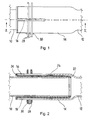
- 10 and 12 are two tubes of an exhaust system for an internal combustion engine of a motor vehicle (not shown). Both tubes 10 and 12 typically are made from steel plate of about 5 mm thickness, having an outside diameter of, e.g., 56 mm. Tube 12 has an expanded bell-shaped socket 14, with an inside diameter substantially larger than the outside diameter of tube 10, for example 65 mm. Socket 14 is cut with two longitudinal slots 16, 18, extending from its end to a point about midway in the bell-shaped socket. The end of tube 10 is inserted as a spigot into socket 14, substantially for its entire length.
- a gasket 20 is interposed between the spigot 10 and socket 14.
- Gasket 20 is a sleeve of thin steel plate, preferably of less than 0.6 mm thickness, even more preferably in the range 0.2 to 0.4 mm.
- Sleeve 20 is provided with an in-turned lip 22 at one end and with an out-turned lip 24 at its opposite end. At a point about one third of the way from lip 22, and therefore outside the extension of slots 16, 18, sleeve 20 has an outwardly salient bead 26.
- gasket 20 is slipped over the spigot end of tube 10 and lip 22 acts as a retainer against the spigot rim.
- lip 24 of the gasket acts as a retainer against the rim of socket 14, so that when the spigot is pushed home into the socket, the action of both lips 22 and 24 will insure that the joint is in the proper position.
- Bead 26 will be slightly squeezed between the spigot and the socket, in an area outside the extension of slots 16, 18.
- the degree of radial projection of bead 26 is chosen so that, when collar 28 is clamped, the bead is compressed radially.
- the compression should be partly elastic, partly plastic, so that the bead is able to recover small dimensional variations due to vibration and/or to temperature change.
- a typical radial projection is about 6 mm from the outside diameter of the gasket.
- the above-described gasket is preferably made from thin-plate tubing, that is cut to size and then roll-formed, in a way known to the person skilled in the art, so that the retaining lips and the bead are obtained.
- pot die forming could be used instead.
- the tubing may be conventional tubing made by roll forming of flat thin steel plate and welding or braising of the adjacent opposite sides.
- Another method of manufacturing the gasket that could be envisaged is deep drawing from a steel workpiece.
- peripheral beads may be made side by side, instead of a single bead.
- out-turned lip although desirable, could be dispensed with.
Landscapes
- Engineering & Computer Science (AREA)
- Chemical & Material Sciences (AREA)
- Combustion & Propulsion (AREA)
- Mechanical Engineering (AREA)
- General Engineering & Computer Science (AREA)
- Gasket Seals (AREA)
Priority Applications (1)
| Application Number | Priority Date | Filing Date | Title |
|---|---|---|---|
| EP99830785A EP1111213A1 (fr) | 1999-12-21 | 1999-12-21 | Joint pour raccords à manchon dans des tuyaux d'échappement de moteurs à combustion interne |
Applications Claiming Priority (1)
| Application Number | Priority Date | Filing Date | Title |
|---|---|---|---|
| EP99830785A EP1111213A1 (fr) | 1999-12-21 | 1999-12-21 | Joint pour raccords à manchon dans des tuyaux d'échappement de moteurs à combustion interne |
Publications (1)
| Publication Number | Publication Date |
|---|---|
| EP1111213A1 true EP1111213A1 (fr) | 2001-06-27 |
Family
ID=8243716
Family Applications (1)
| Application Number | Title | Priority Date | Filing Date |
|---|---|---|---|
| EP99830785A Withdrawn EP1111213A1 (fr) | 1999-12-21 | 1999-12-21 | Joint pour raccords à manchon dans des tuyaux d'échappement de moteurs à combustion interne |
Country Status (1)
| Country | Link |
|---|---|
| EP (1) | EP1111213A1 (fr) |
Cited By (2)
| Publication number | Priority date | Publication date | Assignee | Title |
|---|---|---|---|---|
| EP1403573A1 (fr) * | 2002-09-24 | 2004-03-31 | Honda Giken Kogyo Kabushiki Kaisha | Anneau d'étanchéité inserable et structure d'insertion |
| CN101598079A (zh) * | 2009-07-21 | 2009-12-09 | 重庆隆鑫机车有限公司 | 摩托车发动机 |
Citations (4)
| Publication number | Priority date | Publication date | Assignee | Title |
|---|---|---|---|---|
| DE2612828A1 (de) * | 1976-03-26 | 1977-09-29 | Volkswagenwerk Ag | Loesbare steckverbindung zwischen zwei waermebeanspruchten rohren |
| US4270689A (en) * | 1978-07-07 | 1981-06-02 | Donaldson Company, Inc. | Method of forming a tube structure for use in a lap joint |
| DE8803199U1 (fr) * | 1988-03-10 | 1988-05-05 | Oskar Purucker Maschinenbau Landtechnik, 8659 Untersteinach, De | |
| DE9213063U1 (fr) * | 1992-09-29 | 1992-11-26 | H.J.S. Fahrzeugteile-Fabrik Gmbh & Co, 5750 Menden, De |
-
1999
- 1999-12-21 EP EP99830785A patent/EP1111213A1/fr not_active Withdrawn
Patent Citations (4)
| Publication number | Priority date | Publication date | Assignee | Title |
|---|---|---|---|---|
| DE2612828A1 (de) * | 1976-03-26 | 1977-09-29 | Volkswagenwerk Ag | Loesbare steckverbindung zwischen zwei waermebeanspruchten rohren |
| US4270689A (en) * | 1978-07-07 | 1981-06-02 | Donaldson Company, Inc. | Method of forming a tube structure for use in a lap joint |
| DE8803199U1 (fr) * | 1988-03-10 | 1988-05-05 | Oskar Purucker Maschinenbau Landtechnik, 8659 Untersteinach, De | |
| DE9213063U1 (fr) * | 1992-09-29 | 1992-11-26 | H.J.S. Fahrzeugteile-Fabrik Gmbh & Co, 5750 Menden, De |
Cited By (3)
| Publication number | Priority date | Publication date | Assignee | Title |
|---|---|---|---|---|
| EP1403573A1 (fr) * | 2002-09-24 | 2004-03-31 | Honda Giken Kogyo Kabushiki Kaisha | Anneau d'étanchéité inserable et structure d'insertion |
| US6860487B2 (en) | 2002-09-24 | 2005-03-01 | Honda Giken Kogyo Kabushiki Kaisha | Insertable gasket and inserting structure |
| CN101598079A (zh) * | 2009-07-21 | 2009-12-09 | 重庆隆鑫机车有限公司 | 摩托车发动机 |
Similar Documents
| Publication | Publication Date | Title |
|---|---|---|
| CA2705351C (fr) | Joints de raccords et procedes associes | |
| US20060202480A1 (en) | Pipe clamp assembly with v-ring insert | |
| EP2405172B1 (fr) | Couplage de tuyaux | |
| US7621568B2 (en) | Block fitting and seal structure | |
| US6398269B1 (en) | Tube connection between a collector of a motor vehicle heat exchanger and an exterior line | |
| US20070090644A1 (en) | Integrated Seal for Tube to Hose Connection | |
| US20020135184A1 (en) | Mechanical pipe coupling derived from a standard fitting | |
| US20100181767A1 (en) | Pipe compression joint | |
| EP1602870A1 (fr) | Raccord pour accouplement d'un tube avec un flexible | |
| EP1674686B1 (fr) | Joint de conduits, joint d'étanchéité et procédé de fabrication du joint | |
| US11359754B2 (en) | Flexible pipe element and method for inserting a seal in a flexible pipe element | |
| EP1686248B1 (fr) | Raccord de tuyaux d'échappement d'un véhicule | |
| EP0778437A1 (fr) | Raccord avec verrouillage à ressort | |
| CN105299353A (zh) | 密封垫 | |
| GB2257764A (en) | Clamping device for hose and pipe connector | |
| EP3425249B1 (fr) | Raccord à sertir à joint membranaire | |
| WO1995020123A1 (fr) | Joint a recouvrement entre un tuyau flexible et un tuyau rigide | |
| EP1111213A1 (fr) | Joint pour raccords à manchon dans des tuyaux d'échappement de moteurs à combustion interne | |
| EP0511299B1 (fr) | Procede de fabrication d'un element de raccord symetrique destine en particulier au raccordement entre un dispositif turbo et un refroidisseur a air et element de raccord de ce type | |
| US6508277B1 (en) | Flexible pipe with compressed ends | |
| US20120260488A1 (en) | Flange connector and gasket assembly | |
| CA2822136C (fr) | Joints de raccords et procedes associes | |
| JPH11280973A (ja) | ホ―ス連結具及びその製造方法 | |
| JPH08121666A (ja) | 継手部をもつホース | |
| JPH09133276A (ja) | 管体の接続構造 |
Legal Events
| Date | Code | Title | Description |
|---|---|---|---|
| PUAI | Public reference made under article 153(3) epc to a published international application that has entered the european phase |
Free format text: ORIGINAL CODE: 0009012 |
|
| AK | Designated contracting states |
Kind code of ref document: A1 Designated state(s): AT BE CH CY DE DK ES FI FR GB GR IE IT LI LU MC NL PT SE |
|
| AX | Request for extension of the european patent |
Free format text: AL;LT;LV;MK;RO;SI |
|
| AKX | Designation fees paid | ||
| REG | Reference to a national code |
Ref country code: DE Ref legal event code: 8566 |
|
| STAA | Information on the status of an ep patent application or granted ep patent |
Free format text: STATUS: THE APPLICATION IS DEEMED TO BE WITHDRAWN |
|
| 18D | Application deemed to be withdrawn |
Effective date: 20011228 |