EP1111201B1 - Diamantbeschichtetes Gleitteil - Google Patents
Diamantbeschichtetes Gleitteil Download PDFInfo
- Publication number
- EP1111201B1 EP1111201B1 EP00310704A EP00310704A EP1111201B1 EP 1111201 B1 EP1111201 B1 EP 1111201B1 EP 00310704 A EP00310704 A EP 00310704A EP 00310704 A EP00310704 A EP 00310704A EP 1111201 B1 EP1111201 B1 EP 1111201B1
- Authority
- EP
- European Patent Office
- Prior art keywords
- diamond
- sliding part
- coating layer
- coated
- base material
- Prior art date
- Legal status (The legal status is an assumption and is not a legal conclusion. Google has not performed a legal analysis and makes no representation as to the accuracy of the status listed.)
- Expired - Lifetime
Links
- 239000010432 diamond Substances 0.000 title claims description 106
- 229910003460 diamond Inorganic materials 0.000 title claims description 106
- 239000011247 coating layer Substances 0.000 claims description 36
- 239000000463 material Substances 0.000 claims description 35
- 229910052581 Si3N4 Inorganic materials 0.000 claims description 29
- HQVNEWCFYHHQES-UHFFFAOYSA-N silicon nitride Chemical compound N12[Si]34N5[Si]62N3[Si]51N64 HQVNEWCFYHHQES-UHFFFAOYSA-N 0.000 claims description 29
- 230000007246 mechanism Effects 0.000 claims description 14
- 238000012545 processing Methods 0.000 claims description 6
- 238000002485 combustion reaction Methods 0.000 claims description 5
- 239000002245 particle Substances 0.000 claims description 3
- 238000005299 abrasion Methods 0.000 description 20
- 229910000831 Steel Inorganic materials 0.000 description 12
- 239000010959 steel Substances 0.000 description 12
- 238000012360 testing method Methods 0.000 description 12
- 239000007789 gas Substances 0.000 description 10
- 238000000034 method Methods 0.000 description 10
- 239000002184 metal Substances 0.000 description 8
- 230000009467 reduction Effects 0.000 description 8
- 238000005229 chemical vapour deposition Methods 0.000 description 4
- 239000010410 layer Substances 0.000 description 4
- 230000015572 biosynthetic process Effects 0.000 description 3
- 238000007730 finishing process Methods 0.000 description 3
- 239000000446 fuel Substances 0.000 description 2
- 230000008569 process Effects 0.000 description 2
- 239000002994 raw material Substances 0.000 description 2
- 230000002194 synthesizing effect Effects 0.000 description 2
- 239000004215 Carbon black (E152) Substances 0.000 description 1
- UFHFLCQGNIYNRP-UHFFFAOYSA-N Hydrogen Chemical compound [H][H] UFHFLCQGNIYNRP-UHFFFAOYSA-N 0.000 description 1
- 239000006061 abrasive grain Substances 0.000 description 1
- 239000000853 adhesive Substances 0.000 description 1
- 230000001070 adhesive effect Effects 0.000 description 1
- 230000008901 benefit Effects 0.000 description 1
- 229910010293 ceramic material Inorganic materials 0.000 description 1
- 239000011248 coating agent Substances 0.000 description 1
- 238000000576 coating method Methods 0.000 description 1
- 230000003750 conditioning effect Effects 0.000 description 1
- 238000000354 decomposition reaction Methods 0.000 description 1
- 238000000151 deposition Methods 0.000 description 1
- 238000006073 displacement reaction Methods 0.000 description 1
- 238000011156 evaluation Methods 0.000 description 1
- 238000000227 grinding Methods 0.000 description 1
- 238000010438 heat treatment Methods 0.000 description 1
- 229930195733 hydrocarbon Natural products 0.000 description 1
- 150000002430 hydrocarbons Chemical class 0.000 description 1
- 230000006872 improvement Effects 0.000 description 1
- 230000013011 mating Effects 0.000 description 1
- 238000005259 measurement Methods 0.000 description 1
- 238000007517 polishing process Methods 0.000 description 1
- 238000002360 preparation method Methods 0.000 description 1
- 239000004575 stone Substances 0.000 description 1
- 238000003786 synthesis reaction Methods 0.000 description 1
Images


Classifications
-
- F—MECHANICAL ENGINEERING; LIGHTING; HEATING; WEAPONS; BLASTING
- F01—MACHINES OR ENGINES IN GENERAL; ENGINE PLANTS IN GENERAL; STEAM ENGINES
- F01L—CYCLICALLY OPERATING VALVES FOR MACHINES OR ENGINES
- F01L1/00—Valve-gear or valve arrangements, e.g. lift-valve gear
- F01L1/02—Valve drive
- F01L1/04—Valve drive by means of cams, camshafts, cam discs, eccentrics or the like
-
- F—MECHANICAL ENGINEERING; LIGHTING; HEATING; WEAPONS; BLASTING
- F01—MACHINES OR ENGINES IN GENERAL; ENGINE PLANTS IN GENERAL; STEAM ENGINES
- F01L—CYCLICALLY OPERATING VALVES FOR MACHINES OR ENGINES
- F01L1/00—Valve-gear or valve arrangements, e.g. lift-valve gear
- F01L1/12—Transmitting gear between valve drive and valve
- F01L1/14—Tappets; Push rods
- F01L1/143—Tappets; Push rods for use with overhead camshafts
-
- F—MECHANICAL ENGINEERING; LIGHTING; HEATING; WEAPONS; BLASTING
- F01—MACHINES OR ENGINES IN GENERAL; ENGINE PLANTS IN GENERAL; STEAM ENGINES
- F01L—CYCLICALLY OPERATING VALVES FOR MACHINES OR ENGINES
- F01L3/00—Lift-valve, i.e. cut-off apparatus with closure members having at least a component of their opening and closing motion perpendicular to the closing faces; Parts or accessories thereof
- F01L3/02—Selecting particular materials for valve-members or valve-seats; Valve-members or valve-seats composed of two or more materials
- F01L3/04—Coated valve members or valve-seats
-
- Y—GENERAL TAGGING OF NEW TECHNOLOGICAL DEVELOPMENTS; GENERAL TAGGING OF CROSS-SECTIONAL TECHNOLOGIES SPANNING OVER SEVERAL SECTIONS OF THE IPC; TECHNICAL SUBJECTS COVERED BY FORMER USPC CROSS-REFERENCE ART COLLECTIONS [XRACs] AND DIGESTS
- Y10—TECHNICAL SUBJECTS COVERED BY FORMER USPC
- Y10T—TECHNICAL SUBJECTS COVERED BY FORMER US CLASSIFICATION
- Y10T428/00—Stock material or miscellaneous articles
- Y10T428/24—Structurally defined web or sheet [e.g., overall dimension, etc.]
- Y10T428/24355—Continuous and nonuniform or irregular surface on layer or component [e.g., roofing, etc.]
-
- Y—GENERAL TAGGING OF NEW TECHNOLOGICAL DEVELOPMENTS; GENERAL TAGGING OF CROSS-SECTIONAL TECHNOLOGIES SPANNING OVER SEVERAL SECTIONS OF THE IPC; TECHNICAL SUBJECTS COVERED BY FORMER USPC CROSS-REFERENCE ART COLLECTIONS [XRACs] AND DIGESTS
- Y10—TECHNICAL SUBJECTS COVERED BY FORMER USPC
- Y10T—TECHNICAL SUBJECTS COVERED BY FORMER US CLASSIFICATION
- Y10T428/00—Stock material or miscellaneous articles
- Y10T428/24—Structurally defined web or sheet [e.g., overall dimension, etc.]
- Y10T428/24628—Nonplanar uniform thickness material
-
- Y—GENERAL TAGGING OF NEW TECHNOLOGICAL DEVELOPMENTS; GENERAL TAGGING OF CROSS-SECTIONAL TECHNOLOGIES SPANNING OVER SEVERAL SECTIONS OF THE IPC; TECHNICAL SUBJECTS COVERED BY FORMER USPC CROSS-REFERENCE ART COLLECTIONS [XRACs] AND DIGESTS
- Y10—TECHNICAL SUBJECTS COVERED BY FORMER USPC
- Y10T—TECHNICAL SUBJECTS COVERED BY FORMER US CLASSIFICATION
- Y10T428/00—Stock material or miscellaneous articles
- Y10T428/26—Web or sheet containing structurally defined element or component, the element or component having a specified physical dimension
- Y10T428/263—Coating layer not in excess of 5 mils thick or equivalent
- Y10T428/264—Up to 3 mils
- Y10T428/265—1 mil or less
-
- Y—GENERAL TAGGING OF NEW TECHNOLOGICAL DEVELOPMENTS; GENERAL TAGGING OF CROSS-SECTIONAL TECHNOLOGIES SPANNING OVER SEVERAL SECTIONS OF THE IPC; TECHNICAL SUBJECTS COVERED BY FORMER USPC CROSS-REFERENCE ART COLLECTIONS [XRACs] AND DIGESTS
- Y10—TECHNICAL SUBJECTS COVERED BY FORMER USPC
- Y10T—TECHNICAL SUBJECTS COVERED BY FORMER US CLASSIFICATION
- Y10T428/00—Stock material or miscellaneous articles
- Y10T428/30—Self-sustaining carbon mass or layer with impregnant or other layer
Definitions
- the present invention relates to a sliding part such as an adjusting shim used for a valve train mechanism of an internal combustion engine.
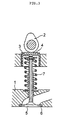
- Figure 3 shows a specific example of the valve train mechanism of an automobile engine.
- 1 is a cylinder head of the engine
- 2 is a cam
- 3 is a valve lifter
- 4 is an adjusting shim
- 5 is a suction and exhaust valve
- 6 is a valve seat
- 7 is a valve spring.
- the adjusting shim 4 is placed between the cam 2 and the valve lifter 3, and therefore the adjusting shim 4 slides with the cam 2 and the valve lifter 3.
- This adjusting shim 4 is used for adjusting the valve clearance, and from the past was usually produced from metal.
- this kind of adjusting shim 4 as well, there is a need for lighter weight and improved abrasion resistance to reduce power loss.
- Japanese patent publication 6-294307 discloses the use of diamond for the preparation of an adjusting shim as a sliding part, or depositing diamond on the base material of the adjusting shim in order to reduce friction work, in other words to reduce the coefficient of friction ⁇ .
- an object of the present invention is to provide a diamond-coated sliding part that is light weight, excellent abrasion resistance, and prevents abrasion of the material of the mating member while being effective in reducing the power loss.
- the diamond-coated sliding part provided by the present invention is a sliding part comprising a base material made of silicon nitride or sialon having a diamond coating layer on the surface thereof, in which the profile bearing length ratio (t p ) at a cutting level of 0.1 ⁇ m specified in Japanese Industrial Standard (JIS) B 0601 is 60% or greater for the sliding surface of the diamond coating layer.
- JIS Japanese Industrial Standard
- the profile bearing length ratio (t p ) is adjusted as noted above, and the diamond coating layer surface is made smooth or having no projecting parts.
- Figure 1 is a vertical cross section of an adjusting shim.
- Figure 2 is a vertical cross section of an adjusting shim installed into a valve lifter.
- Figure 3 is a vertical cross section of the valve train mechanism of an automobile engine.
- Figure 4 is a vertical cross section of a motoring device used in the tests in the examples.
- the base material is made from silicon nitride (Si 3 N 4 ) or sialon (Si-Al-O-N). Both silicon nitride and sialon are ceramic materials, and are very light compared to metal while at the same time having a high level of hardness, excellent abrasion resistance and high heat resistance.
- silicon nitride or sialon used for the base material, it is preferable that the three-point flexural strength ( ⁇ 3 b ) be 1000 MPa or greater because this is used as a sliding part.
- the diamond coating layer provided on the base material is preferably a gas phase synthetic diamond formed using a known PVD method or CVD method.
- CVD method it is possible to decompose raw material gases such as hydrocarbon gas and hydrogen gas and to deposit diamond from the gas phase on the base material, and depending on the decomposition process of the raw material gas, methods such as thermal heating filament method, microwave plasma method, and high frequency plasma method are known.
- diamond has a high degree of hardness and has excellent thermal conductivity, so it is well suited as an abrasion resistant sliding coating film. Also, the difference in the thermal expansion coefficient and modulus of longitudinal elasticity between diamond and the base material (i.e., silicon nitride or sialon) is small, so the diamond coating layer does not peel from the base material. It is preferable that the thickness of the diamond coating layer be in the range of 0.5 to 20 ⁇ m. At less than 0.5 ⁇ m, it is not possible to obtain sufficient strength as a diamond, and at greater than 20 ⁇ m, the cost becomes high. However, if there is a benefit that justifies the cost, it is acceptable to form the layer at a thickness greater than 20 ⁇ m.
- a finish processing in other words, part of the peaks of higher protrusions of the protruding parts is removed to reduce the height of the protrusions, and thereby the surface is made smooth or the protruding parts are eliminated from the surface profile.
- this finish processing it is possible to use a polishing process using a diamond grinding stone, for example, or to use a lapping process using fine free abrasive grains of 10 ⁇ m or less.
- the profile bearing length ratio (t p ) is adjusted to be 60% or greater at a cutting level of 0.1 ⁇ m.
- the surface state of the diamond coating layer formed on the base material can also be adjusted by conditioning the base material surface state or by controlling the film forming conditions using a gas phase synthesizing method or the like. Therefore, for the present invention, by controlling these various conditions, at the sliding surface of the diamond coating layer, the profile bearing length ratio (t p ) is adjusted to be 60% or greater at a cutting level of 0.1 ⁇ m, and the surface can be smooth or have a surface state with no projecting parts in the surface profile, and in this case, the aforementioned finishing process is not needed.
- the profile bearing length ratio (t p ) be 60% or greater at a cutting level of 0.1 ⁇ m in this way, the loss torque is smaller than that of the metal made sliding parts of the prior art, and the loss torque itself is also smaller as the aforementioned profile bearing length ratio increases, so the abrasion loss of the counterpart member is reduced.
- the profile bearing length ratio (t p ) at a cutting level of 0.1 ⁇ m is made 85% or greater, no more reduction in loss torque can be obtained, and the abrasion loss of the counterpart member is almost the same.
- profile bearing length ratio (t p ) is the ratio of the sum of cut lengths obtained at the time of cutting the roughness curve within the range of the reference length at a certain cutting levels parallel to the top of profile peak line (profile bearing length) to the reference length and the ratio is expressed in percentage. Measurements of the profile bearing length ratio (t p ) was performed in compliance with the aforementioned JIS, and the reference length was 0.25 mm while the evaluation length was 1.25 mm.
- the profile bearing length ratio (t p ) for a cutting level of 0.1 ⁇ m is adjusted by the finishing process or by adjustment of the film forming conditions, and the surface of the diamond coating layer is made smooth or projecting parts of the surface profile are eliminated, so that it is possible to reduce friction loss that occurs with the opposite member and to suppress the power loss. Therefore the sliding part of the present invention is excellent as a sliding part used for a valve train mechanism of an internal combustion engine of an automobile engine or the like.
- silicon nitride or sialon as the base material, it is possible to make this lighter than items made of metal or using metal as the base material, and the difference is the modulus of longitudinal elasticity and thermal expansion coefficient between the base material and diamond is small, so the adhesive force of the diamond coating layer becomes greater.
- a gas phase synthetic diamond was deposited by a known filament CVD method on each of the base materials made from Si 3 N 4 sintered bodies having different three-point flexural strengths to produce adjusting shims.
- the adjusting shims thus obtained as samples all had a diameter of 30 mm and a thickness of 5 mm.
- the contact surface 4a of the adjusting shim 4 to be brought into contact with the cam was finished by lapping.
- the profile bearing length ratio at a cutting level of 0.1 ⁇ m shown as t p 0.1 in Table 1 below
- 4b and 4c in figure 1 indicate the contact surfaces with the valve lifter.
- Example 2 Each sample adjusting shim shown in Table 2 below produced in the same manner as the aforementioned Example 1 was installed into the motoring device of figure 4 used for Example 1, and a continuous drive test was performed for 200 hours at a fixed revolution rate (6000 rpm converted to engine revolution rate).
- Example 2 the same test as described above was also performed on an adjusting shim(sample 11A) made from a conventional Cr-Mo steel and on adjusting shims (surface polished sample 20A and unpolished sample 19A) made only from an Si 3 N 4 sintered body, and the results are shown together in table 2.
- a gas phase synthetic diamond was deposited by a known filament CVD method on each base material made from Si 3 N 4 sintered bodies having different three-point flexural strengths to produce adjusting shims. All the sample adjusting shims had a diameter of 30 mm and a thickness of 5 mm.
- Example 4 the same test as described above was also performed on the adjusting shim (sample 11B) made from the conventional Cr-Mo steel and on the adjusting shims (surface polished sample 20B and unpolished sample 19B) made only from the Si 3 N 4 sintered body, and the results are shown together in Table 4.
- the present invention it is possible to provide an excellent highly reliable diamond-coated sliding part that is light, has excellent abrasion resistance, prevents abrasion of the counterpart member with which the sliding part slides, and can greatly reduce power loss.
- this diamond-coated sliding part it is possible to improve the abrasion resistance and the friction loss that occurs between the diamond coating layer and the opposite member. It is also possible to reduce power loss as a valve train mechanism of an internal combustion engine, and to improve fuel consumption and durability remarkably.
Landscapes
- Engineering & Computer Science (AREA)
- Mechanical Engineering (AREA)
- General Engineering & Computer Science (AREA)
- Valve-Gear Or Valve Arrangements (AREA)
- Sliding-Contact Bearings (AREA)
Claims (8)
- Gleitteil mit Diamant-Überzug, das ein Grundmaterial umfasst, welches aus Siliziumnitrid oder Sialon besteht und eine Diamant-Überzugsschicht an einer Fläche desselben aufweist, wobei ein Flächentraganteil (tp) bei einer Schnitthöhe von 0,1 µm (spezifiziert in JIS B 0601) 60% oder mehr für die Gleitfläche der Diamant-Überzugsschicht beträgt.
- Gleitteil mit Diamant-Überzug nach Anspruch 1, wobei lediglich ein sehr kleiner Teil von Spitzen von Diamantteilchen, die von der Oberfläche der Diamant-Überzugsschicht vorstehen, einer Fertigbearbeitung unterzogen worden ist.
- Gleitteil mit Diamant-Überzug nach Anspruch 1, wobei die Oberfläche der Diamant-Überzugsschicht keiner Fertigbearbeitung unterzogen wurde.
- Gleitteil mit Diamant-Überzug nach einem der Ansprüche 1 bis 3, wobei das Grundmaterial aus Siliziumnitrid oder Sialon eine Dreipunkt-Biegefestigkeit von 1000 MPa oder mehr hat.
- Gleitteil mit Diamant-Überzug nach einem der Ansprüche 1 bis 4, wobei die Diamant-Überzugsschicht aus künstlichem CVD-Diamant besteht.
- Gleitteil mit Diamant-Überzug nach einem der Ansprüche 1 bis 5, wobei die Dicke der Diamant-Überzugsschicht zwischen 0,5 und 20 µm beträgt.
- Gleitteil mit Diamant-Überzug nach einem der Ansprüche 1 bis 6, wobei das Gleitteil für den Ventiltriebmechanismus eines Verbrennungsmotors eingesetzt wird.
- Ventiltriebmechanismus für einen Verbrennungsmotor, wobei der Mechanismus ein Gleitteil mit Diamant-Überzug nach einem der Ansprüche 1 bis 7 als ein Einstellplättchen umfasst.
Applications Claiming Priority (4)
| Application Number | Priority Date | Filing Date | Title |
|---|---|---|---|
| JP34220699A JP2001158689A (ja) | 1999-12-01 | 1999-12-01 | ダイヤモンド被覆摺動部品 |
| JP34220699 | 1999-12-01 | ||
| JP34220599A JP2001158965A (ja) | 1999-12-01 | 1999-12-01 | ダイヤモンド被覆摺動部品 |
| JP34220599 | 1999-12-01 |
Publications (3)
| Publication Number | Publication Date |
|---|---|
| EP1111201A2 EP1111201A2 (de) | 2001-06-27 |
| EP1111201A3 EP1111201A3 (de) | 2002-04-03 |
| EP1111201B1 true EP1111201B1 (de) | 2003-09-03 |
Family
ID=26577186
Family Applications (1)
| Application Number | Title | Priority Date | Filing Date |
|---|---|---|---|
| EP00310704A Expired - Lifetime EP1111201B1 (de) | 1999-12-01 | 2000-12-01 | Diamantbeschichtetes Gleitteil |
Country Status (4)
| Country | Link |
|---|---|
| US (1) | US6534170B2 (de) |
| EP (1) | EP1111201B1 (de) |
| KR (1) | KR20010061997A (de) |
| DE (1) | DE60004956T2 (de) |
Families Citing this family (3)
| Publication number | Priority date | Publication date | Assignee | Title |
|---|---|---|---|---|
| US20080236535A1 (en) * | 2007-04-02 | 2008-10-02 | Van Driessche Marc Gilbert Ivan | Rotary valve for an internal combustion engine |
| JP2009036249A (ja) * | 2007-07-31 | 2009-02-19 | Jtekt Corp | 湿式摩擦板 |
| KR101439131B1 (ko) * | 2012-09-21 | 2014-09-11 | 현대자동차주식회사 | 흡배기 밸브용 코팅재 및 이의 제조방법 |
Family Cites Families (9)
| Publication number | Priority date | Publication date | Assignee | Title |
|---|---|---|---|---|
| US5040501A (en) * | 1987-03-31 | 1991-08-20 | Lemelson Jerome H | Valves and valve components |
| US4960643A (en) * | 1987-03-31 | 1990-10-02 | Lemelson Jerome H | Composite synthetic materials |
| US4990403A (en) | 1989-01-20 | 1991-02-05 | Idemitsu Petrochemical Company Limited | Diamond coated sintered body |
| DE69017404T2 (de) | 1989-12-28 | 1995-11-09 | Idemitsu Petrochemical Co | Diamantbeschichteter Sinterkörper und Verfahren zu seiner Herstellung. |
| EP0577877B1 (de) | 1991-09-04 | 1995-10-18 | Sumitomo Electric Industries, Ltd. | Spielausgleichselement |
| JP3123259B2 (ja) | 1992-10-29 | 2001-01-09 | 住友電気工業株式会社 | アジャスティングシム及びカム |
| JP3348794B2 (ja) | 1993-04-09 | 2002-11-20 | 住友電気工業株式会社 | アジャスティングシム |
| WO1999047810A1 (en) * | 1998-03-19 | 1999-09-23 | Sumitomo Electric Industries, Ltd. | Combination of shim and cam |
| JPH11315705A (ja) | 1998-04-30 | 1999-11-16 | Sumitomo Electric Ind Ltd | 摺動装置の摺動部品 |
-
2000
- 2000-11-30 KR KR1020000071792A patent/KR20010061997A/ko not_active Withdrawn
- 2000-11-30 US US09/725,854 patent/US6534170B2/en not_active Expired - Fee Related
- 2000-12-01 EP EP00310704A patent/EP1111201B1/de not_active Expired - Lifetime
- 2000-12-01 DE DE60004956T patent/DE60004956T2/de not_active Expired - Fee Related
Also Published As
| Publication number | Publication date |
|---|---|
| EP1111201A3 (de) | 2002-04-03 |
| US6534170B2 (en) | 2003-03-18 |
| DE60004956T2 (de) | 2004-07-15 |
| DE60004956D1 (de) | 2003-10-09 |
| US20010003278A1 (en) | 2001-06-14 |
| KR20010061997A (ko) | 2001-07-07 |
| EP1111201A2 (de) | 2001-06-27 |
Similar Documents
| Publication | Publication Date | Title |
|---|---|---|
| US6237441B1 (en) | Combination of shim and cam | |
| JP3348794B2 (ja) | アジャスティングシム | |
| JP2000303161A (ja) | 摺動部材の表面処理方法及び該方法を用いた摺動部材の表面平滑化方法 | |
| JP4141473B2 (ja) | 窒化バルブリフタおよびその製造方法 | |
| EP1111201B1 (de) | Diamantbeschichtetes Gleitteil | |
| KR100320698B1 (ko) | 심 및 캠의 조합체 | |
| JPH11303709A (ja) | 燃料噴射ポンプ | |
| KR0148245B1 (ko) | 조정심과 캠의 조합 | |
| CA2181060C (en) | Ceramic sliding part | |
| JP3625041B2 (ja) | タペット | |
| JP2001158965A (ja) | ダイヤモンド被覆摺動部品 | |
| EP4202199A1 (de) | Gleitelement | |
| JP2001158689A (ja) | ダイヤモンド被覆摺動部品 | |
| US5358797A (en) | Adjusting shim | |
| JP3147538B2 (ja) | カムフォロワおよびその製造方法 | |
| JPH0641722A (ja) | 摺動部材およびその製造方法 | |
| EP0577877B1 (de) | Spielausgleichselement | |
| US6220757B1 (en) | Sliding part for a sliding mechanism | |
| Langer et al. | Considerations in the Manufacture of Ceramic Valve Train Components and Wear | |
| US6050881A (en) | Surface finishing covalent-ionic ceramics | |
| JP4037143B2 (ja) | 摺動部材及びその製造方法 | |
| JP2926992B2 (ja) | セラミック摺動部品 | |
| JPH0641721A (ja) | 摺動部材およびその製造方法 | |
| JP2006214314A (ja) | バルブリフター及びシムの製造方法 | |
| JPWO1999047810A1 (ja) | シムとカムの組合せ |
Legal Events
| Date | Code | Title | Description |
|---|---|---|---|
| PUAI | Public reference made under article 153(3) epc to a published international application that has entered the european phase |
Free format text: ORIGINAL CODE: 0009012 |
|
| AK | Designated contracting states |
Kind code of ref document: A2 Designated state(s): DE FR GB IT SE Kind code of ref document: A2 Designated state(s): AT BE CH CY DE DK ES FI FR GB GR IE IT LI LU MC NL PT SE TR |
|
| AX | Request for extension of the european patent |
Free format text: AL;LT;LV;MK;RO;SI |
|
| PUAL | Search report despatched |
Free format text: ORIGINAL CODE: 0009013 |
|
| AK | Designated contracting states |
Kind code of ref document: A3 Designated state(s): AT BE CH CY DE DK ES FI FR GB GR IE IT LI LU MC NL PT SE TR |
|
| AX | Request for extension of the european patent |
Free format text: AL;LT;LV;MK;RO;SI |
|
| RIC1 | Information provided on ipc code assigned before grant |
Free format text: 7F 01L 3/04 A, 7F 01L 1/14 B, 7C 23C 16/27 B, 7F 01L 1/20 B |
|
| 17P | Request for examination filed |
Effective date: 20020514 |
|
| AKX | Designation fees paid |
Free format text: DE FR GB IT SE |
|
| GRAH | Despatch of communication of intention to grant a patent |
Free format text: ORIGINAL CODE: EPIDOS IGRA |
|
| RTI1 | Title (correction) |
Free format text: DIAMOND-COATED SLIDING PART |
|
| GRAS | Grant fee paid |
Free format text: ORIGINAL CODE: EPIDOSNIGR3 |
|
| GRAA | (expected) grant |
Free format text: ORIGINAL CODE: 0009210 |
|
| AK | Designated contracting states |
Kind code of ref document: B1 Designated state(s): DE FR GB IT SE |
|
| REG | Reference to a national code |
Ref country code: GB Ref legal event code: FG4D |
|
| REF | Corresponds to: |
Ref document number: 60004956 Country of ref document: DE Date of ref document: 20031009 Kind code of ref document: P |
|
| REG | Reference to a national code |
Ref country code: IE Ref legal event code: FG4D |
|
| REG | Reference to a national code |
Ref country code: SE Ref legal event code: TRGR |
|
| ET | Fr: translation filed | ||
| PLBE | No opposition filed within time limit |
Free format text: ORIGINAL CODE: 0009261 |
|
| STAA | Information on the status of an ep patent application or granted ep patent |
Free format text: STATUS: NO OPPOSITION FILED WITHIN TIME LIMIT |
|
| 26N | No opposition filed |
Effective date: 20040604 |
|
| REG | Reference to a national code |
Ref country code: IE Ref legal event code: MM4A |
|
| PGFP | Annual fee paid to national office [announced via postgrant information from national office to epo] |
Ref country code: IT Payment date: 20071221 Year of fee payment: 8 |
|
| PGFP | Annual fee paid to national office [announced via postgrant information from national office to epo] |
Ref country code: SE Payment date: 20071205 Year of fee payment: 8 |
|
| PGFP | Annual fee paid to national office [announced via postgrant information from national office to epo] |
Ref country code: FR Payment date: 20071210 Year of fee payment: 8 Ref country code: GB Payment date: 20071128 Year of fee payment: 8 |
|
| PGFP | Annual fee paid to national office [announced via postgrant information from national office to epo] |
Ref country code: DE Payment date: 20071129 Year of fee payment: 8 |
|
| EUG | Se: european patent has lapsed | ||
| GBPC | Gb: european patent ceased through non-payment of renewal fee |
Effective date: 20081201 |
|
| REG | Reference to a national code |
Ref country code: FR Ref legal event code: ST Effective date: 20090831 |
|
| PG25 | Lapsed in a contracting state [announced via postgrant information from national office to epo] |
Ref country code: DE Free format text: LAPSE BECAUSE OF NON-PAYMENT OF DUE FEES Effective date: 20090701 |
|
| PG25 | Lapsed in a contracting state [announced via postgrant information from national office to epo] |
Ref country code: GB Free format text: LAPSE BECAUSE OF NON-PAYMENT OF DUE FEES Effective date: 20081201 |
|
| PG25 | Lapsed in a contracting state [announced via postgrant information from national office to epo] |
Ref country code: FR Free format text: LAPSE BECAUSE OF NON-PAYMENT OF DUE FEES Effective date: 20081231 |
|
| PG25 | Lapsed in a contracting state [announced via postgrant information from national office to epo] |
Ref country code: SE Free format text: LAPSE BECAUSE OF NON-PAYMENT OF DUE FEES Effective date: 20081202 |
|
| PG25 | Lapsed in a contracting state [announced via postgrant information from national office to epo] |
Ref country code: IT Free format text: LAPSE BECAUSE OF NON-PAYMENT OF DUE FEES Effective date: 20081201 |