EP1111113A2 - Process and apparatus for the production of a mineral fibreboard - Google Patents
Process and apparatus for the production of a mineral fibreboard Download PDFInfo
- Publication number
- EP1111113A2 EP1111113A2 EP01102183A EP01102183A EP1111113A2 EP 1111113 A2 EP1111113 A2 EP 1111113A2 EP 01102183 A EP01102183 A EP 01102183A EP 01102183 A EP01102183 A EP 01102183A EP 1111113 A2 EP1111113 A2 EP 1111113A2
- Authority
- EP
- European Patent Office
- Prior art keywords
- fleece
- sub
- webs
- compression
- separating device
- Prior art date
- Legal status (The legal status is an assumption and is not a legal conclusion. Google has not performed a legal analysis and makes no representation as to the accuracy of the status listed.)
- Granted
Links
Images


Classifications
-
- D—TEXTILES; PAPER
- D04—BRAIDING; LACE-MAKING; KNITTING; TRIMMINGS; NON-WOVEN FABRICS
- D04H—MAKING TEXTILE FABRICS, e.g. FROM FIBRES OR FILAMENTARY MATERIAL; FABRICS MADE BY SUCH PROCESSES OR APPARATUS, e.g. FELTS, NON-WOVEN FABRICS; COTTON-WOOL; WADDING ; NON-WOVEN FABRICS FROM STAPLE FIBRES, FILAMENTS OR YARNS, BONDED WITH AT LEAST ONE WEB-LIKE MATERIAL DURING THEIR CONSOLIDATION
- D04H1/00—Non-woven fabrics formed wholly or mainly of staple fibres or like relatively short fibres
- D04H1/40—Non-woven fabrics formed wholly or mainly of staple fibres or like relatively short fibres from fleeces or layers composed of fibres without existing or potential cohesive properties
- D04H1/58—Non-woven fabrics formed wholly or mainly of staple fibres or like relatively short fibres from fleeces or layers composed of fibres without existing or potential cohesive properties by applying, incorporating or activating chemical or thermoplastic bonding agents, e.g. adhesives
- D04H1/64—Non-woven fabrics formed wholly or mainly of staple fibres or like relatively short fibres from fleeces or layers composed of fibres without existing or potential cohesive properties by applying, incorporating or activating chemical or thermoplastic bonding agents, e.g. adhesives the bonding agent being applied in wet state, e.g. chemical agents in dispersions or solutions
- D04H1/645—Impregnation followed by a solidification process
-
- D—TEXTILES; PAPER
- D04—BRAIDING; LACE-MAKING; KNITTING; TRIMMINGS; NON-WOVEN FABRICS
- D04H—MAKING TEXTILE FABRICS, e.g. FROM FIBRES OR FILAMENTARY MATERIAL; FABRICS MADE BY SUCH PROCESSES OR APPARATUS, e.g. FELTS, NON-WOVEN FABRICS; COTTON-WOOL; WADDING ; NON-WOVEN FABRICS FROM STAPLE FIBRES, FILAMENTS OR YARNS, BONDED WITH AT LEAST ONE WEB-LIKE MATERIAL DURING THEIR CONSOLIDATION
- D04H1/00—Non-woven fabrics formed wholly or mainly of staple fibres or like relatively short fibres
- D04H1/40—Non-woven fabrics formed wholly or mainly of staple fibres or like relatively short fibres from fleeces or layers composed of fibres without existing or potential cohesive properties
- D04H1/42—Non-woven fabrics formed wholly or mainly of staple fibres or like relatively short fibres from fleeces or layers composed of fibres without existing or potential cohesive properties characterised by the use of certain kinds of fibres insofar as this use has no preponderant influence on the consolidation of the fleece
- D04H1/4209—Inorganic fibres
- D04H1/4218—Glass fibres
- D04H1/4226—Glass fibres characterised by the apparatus for manufacturing the glass fleece
-
- D—TEXTILES; PAPER
- D04—BRAIDING; LACE-MAKING; KNITTING; TRIMMINGS; NON-WOVEN FABRICS
- D04H—MAKING TEXTILE FABRICS, e.g. FROM FIBRES OR FILAMENTARY MATERIAL; FABRICS MADE BY SUCH PROCESSES OR APPARATUS, e.g. FELTS, NON-WOVEN FABRICS; COTTON-WOOL; WADDING ; NON-WOVEN FABRICS FROM STAPLE FIBRES, FILAMENTS OR YARNS, BONDED WITH AT LEAST ONE WEB-LIKE MATERIAL DURING THEIR CONSOLIDATION
- D04H1/00—Non-woven fabrics formed wholly or mainly of staple fibres or like relatively short fibres
- D04H1/40—Non-woven fabrics formed wholly or mainly of staple fibres or like relatively short fibres from fleeces or layers composed of fibres without existing or potential cohesive properties
- D04H1/58—Non-woven fabrics formed wholly or mainly of staple fibres or like relatively short fibres from fleeces or layers composed of fibres without existing or potential cohesive properties by applying, incorporating or activating chemical or thermoplastic bonding agents, e.g. adhesives
- D04H1/593—Non-woven fabrics formed wholly or mainly of staple fibres or like relatively short fibres from fleeces or layers composed of fibres without existing or potential cohesive properties by applying, incorporating or activating chemical or thermoplastic bonding agents, e.g. adhesives to layered webs
-
- D—TEXTILES; PAPER
- D04—BRAIDING; LACE-MAKING; KNITTING; TRIMMINGS; NON-WOVEN FABRICS
- D04H—MAKING TEXTILE FABRICS, e.g. FROM FIBRES OR FILAMENTARY MATERIAL; FABRICS MADE BY SUCH PROCESSES OR APPARATUS, e.g. FELTS, NON-WOVEN FABRICS; COTTON-WOOL; WADDING ; NON-WOVEN FABRICS FROM STAPLE FIBRES, FILAMENTS OR YARNS, BONDED WITH AT LEAST ONE WEB-LIKE MATERIAL DURING THEIR CONSOLIDATION
- D04H1/00—Non-woven fabrics formed wholly or mainly of staple fibres or like relatively short fibres
- D04H1/40—Non-woven fabrics formed wholly or mainly of staple fibres or like relatively short fibres from fleeces or layers composed of fibres without existing or potential cohesive properties
- D04H1/58—Non-woven fabrics formed wholly or mainly of staple fibres or like relatively short fibres from fleeces or layers composed of fibres without existing or potential cohesive properties by applying, incorporating or activating chemical or thermoplastic bonding agents, e.g. adhesives
- D04H1/64—Non-woven fabrics formed wholly or mainly of staple fibres or like relatively short fibres from fleeces or layers composed of fibres without existing or potential cohesive properties by applying, incorporating or activating chemical or thermoplastic bonding agents, e.g. adhesives the bonding agent being applied in wet state, e.g. chemical agents in dispersions or solutions
- D04H1/655—Non-woven fabrics formed wholly or mainly of staple fibres or like relatively short fibres from fleeces or layers composed of fibres without existing or potential cohesive properties by applying, incorporating or activating chemical or thermoplastic bonding agents, e.g. adhesives the bonding agent being applied in wet state, e.g. chemical agents in dispersions or solutions characterised by the apparatus for applying bonding agents
-
- D—TEXTILES; PAPER
- D04—BRAIDING; LACE-MAKING; KNITTING; TRIMMINGS; NON-WOVEN FABRICS
- D04H—MAKING TEXTILE FABRICS, e.g. FROM FIBRES OR FILAMENTARY MATERIAL; FABRICS MADE BY SUCH PROCESSES OR APPARATUS, e.g. FELTS, NON-WOVEN FABRICS; COTTON-WOOL; WADDING ; NON-WOVEN FABRICS FROM STAPLE FIBRES, FILAMENTS OR YARNS, BONDED WITH AT LEAST ONE WEB-LIKE MATERIAL DURING THEIR CONSOLIDATION
- D04H1/00—Non-woven fabrics formed wholly or mainly of staple fibres or like relatively short fibres
- D04H1/70—Non-woven fabrics formed wholly or mainly of staple fibres or like relatively short fibres characterised by the method of forming fleeces or layers, e.g. reorientation of fibres
- D04H1/74—Non-woven fabrics formed wholly or mainly of staple fibres or like relatively short fibres characterised by the method of forming fleeces or layers, e.g. reorientation of fibres the fibres being orientated, e.g. in parallel (anisotropic fleeces)
-
- D—TEXTILES; PAPER
- D04—BRAIDING; LACE-MAKING; KNITTING; TRIMMINGS; NON-WOVEN FABRICS
- D04H—MAKING TEXTILE FABRICS, e.g. FROM FIBRES OR FILAMENTARY MATERIAL; FABRICS MADE BY SUCH PROCESSES OR APPARATUS, e.g. FELTS, NON-WOVEN FABRICS; COTTON-WOOL; WADDING ; NON-WOVEN FABRICS FROM STAPLE FIBRES, FILAMENTS OR YARNS, BONDED WITH AT LEAST ONE WEB-LIKE MATERIAL DURING THEIR CONSOLIDATION
- D04H13/00—Other non-woven fabrics
Definitions
- This invention relates to a process and apparatus for the production of a mineral fibreboard.
- the invention we provide a continuous process for the production of a two-ply or multi-ply bonded mineral fibreboard from a mineral fibre fleece by longitudinal precompression of the fleece in a compression unit, feeding the precompressed fleece to a separating device, separating the fleece by means of the separating device into two or more sub-webs, compressing at least one sub-web in the direction of the thickness, followed by combining the sub-webs and transporting the same on to a bonding station in which the fleece is bonded, characterised in that the break-out of the tensioned sub-webs between the compression unit and the bonding station is prevented by means that prevent break out.
- the means that prevent break out can include constraining means.
- the thickness and longitudinally compressed fleece is divided into two or more sub-webs parallel to the larger surfaces, while to prevent any deformation in the thickness direction the sub-webs are each held at the opposite large surfaces. At least one of the webs is compressed in the direction of the thickness and/or longitudinally with the sub-webs are then combined and subsequently bonded. Multi-ply products can be produced by this process.
- the contact surfaces of the sub-webs can be sprayed or impregnated with binder before being combined.
- the combined webs held together by suitable means can be thickness compressed once again.
- the webs are longitudinally compressed before bonding.
- the longitudinal compression can be effected in a ratio of 1.1:1 to maximum 2:1.
- the contact surfaces can be increased in size by a final longitudinal compression so that the bonding of the sub-webs is improved.
- a process for the continuous production of a mineral fibre board having two or more layers of different densities by precompressing a fibre felt, feeding the precompressed felt to a separating device, separating the felt into two or more sub-webs, compressing at least one sub-web in the direction of the thickness, followed by combining the sub-webs, and transporting the same on to a bonding station in which the felt is bonded, characterised in that the fibre felt is longitudinally compressed before the separating device in a compression unit without compression in the direction of the thickness in a continuous compression zone in which the nominal thickness of the product is maintained, and in that break-out of the tensioned sub-webs between the compression unit and the bonding station is prevented by constraining means.
- We also provide novel apparatus for the continuous production of a bonded mineral fibreboard from a mineral fibre fleece comprising means disposed consecutively in the conveying direction F for precompressing the fleece, first transport means for transporting the fleece to a separating device, a separating device for separating the fleece into two or more sub-webs, means for compressing at least one sub-web in the direction of the thickness, second transport means for subsequently combining the sub-webs and transporting the same on to the bonding station in which the fleece is bonded, a bonding station for bonding the compressed fleece characterised in that the first transport means form a compression unit which comprises at least two conveyor pairs disposed consecutively in the conveying direction, and in that means are provided to prevent break-out of the tensioned sub-webs between the compression unit and the bonding station.
- the processes and apparatus of the invention differ from some known processes and apparatus essentially in that the precompressed web is compressed further in the thickness and/or longitudinal direction, particularly the longitudinal direction, by a compression unit, so that the sub-webs produced can already have relatively high densities and different fibre structures before being split.
- the advantage of this for example, in the case of two-ply boards, is that the lower-density layer, unlike conventional boards, has a better compressive strength and tensile strength perpendicularly to the large surfaces. A specific tensile and compressive strength can therefore be achieved with reduced use of material, particularly a smaller quantity of fibre, compared with the known processes.
- suitable hold-down means and/or conveyors are advantageously provided to hold the fleece webs at the large surfaces.
- At least one of the split sub-webs can be thickness-compressed.
- a higher piercing strength can be obtained in this way.
- the one thickness-compressed sub-web can also be longitudinally compressed. Rolling the reoriented fibres flat by thickness compression may necessitate compensation of the resulting elongation.
- the contact surfaces of the sub-webs can additionally be provided with binder before being combined.
- the quantity of binder initially applied to the fibres is already sufficient to achieve a good bond between the sub-webs on curing of the binder.
- Another possibility for improving the bond between the sub-webs is to compress the combined webs in length before curing. By contracting the webs, e.g. in a ratio of 1.1:1 to a maximum 2:1 it is possible to enlarge the contact surfaces and hence obtain a better bond between the layers.
- One problem in connection with the continuous production of two-ply or multi-ply products may be soiling of the band knife used by the binder adhering to the fibres.
- One advantageous variant of the process therefore proposes continuously cleaning the separating device. This can be effected, for example, by means of a solvent jet, e.g. water, directed to the cutting edge of the band knife.
- the longitudinal compression is effected by passing the fleece through a compression unit comprising a plurality of conveyor pairs disposed consecutively in the direction of conveyance, the speed of at least one conveyor pair being less than that of the preceding conveyor pair.
- the precompressed fleece is longitudinally compressed in at least one stage. Longitudinal compression enables the fibres to be reoriented so that, in particular, the compressive strength and tensile strength perpendicularly to the large surfaces are improved. As a result of the fibre structure optimisation it is possible to reduce the resources used.
- the spacing of the opposite conveyors of a conveyor pair is set to approximately 0.5 to 0.1 times the spacing of the following conveyors, the conveying path defined by the two conveyor pairs being disposed substantially in alignment and the circumferential speed at least of the directly following pair being less than the circumferential speed of the preceding conveyor pair.
- the spacing of the opposite conveyors of a conveyor pair is set to approximately 0.5 to 0.1 times the spacing of the following conveyors, the conveying path defined by the two conveyor pairs being disposed substantially in alignment and the circumferential speed at least of the directly following pair being less than the circumferential speed of the preceding conveyor pair.
- the fleece before entry to the compression unit, is already compressed to approximately 0.8 to 1.5 times, preferably 0.9 to 1.3 times the nominal thickness and quite particularly preferably to the approximate nominal thickness of the finished product, so that there is substantially only a longitudinal compression by the conveyors of the compression unit.
- the longitudinal compression can take place in a continuous compression zone in which the nominal thickness of the product is maintained.
- a very homogeneous gross microdensity can be obtained if the fleece is already precompressed to approximately the nominal thickness of the finished product before the compression unit and is then only longitudinally compressed.
- the mineral fibre fleece is advantageously compressed in length by a factor of 2 to 10, preferably by a factor of 2.5 to 5 and quite particularly preferably by a factor of about 2.5 to 3.5. In some cases, for example when the density of the bottom sub-web of the finished product is to be less than approximately 100 kg/m3, a simultaneous longitudinal and thickness compression may be indicated.
- the degree of thickness compression is advantageously less than 2 and preferably less than 1.5.
- the conveyors of the compression unit may be conveyor belts
- the conveyors in a particularly preferred embodiment are constructed as roller conveyors.
- rollers have the advantage that the fleece is repeatedly expanded and compressed by the rollers during compression.
- the fibres are uniformly felted and no preferential fibre orientation can be detected (Fig. 11).
- Fig. 11 On an enlarged scale it has been found that the random-orientation fibres are partly arranged in a corrugated pattern. This type of fibre structure is designated a corrugated fibre structure by the inventors.
- Another desirable effect is the compaction of the fleece web surfaces which is possible by means of rollers.
- each roller conveyor comprises in each case two opposite groups of at least two rollers in each case, the rollers of a conveyor each being driven at the same circumferential speed. Since the rollers are combined in groups of at least two rollers, the compression unit and its control are greatly simplified.
- the fleece is stretched in the conveying direction before the separating device. Expanding the fleece can prevent unwanted pleating or breaking-out of the fleece web, e.g. on transition from the compression unit to the separating device.
- the fleece may consist of glass wool, rock wool or other synthetic fibres.
- the fleece consists essentially of rock wool fibres and contains non-cured binder.
- the binder content by weight can be between approximately 0.7 and 4%.
- the binder is preferably curable in a curing oven. Bonding of the fleece can, however, be effected by needling or felting.
- mineral fibres of an average length between approximately 0.3 and 50 mm preferably between approximately 0.5 and 15 mm and of a thickness between approximately 1 to 12 ⁇ m, preferably between approximately 3 and 8 ⁇ m are used.
- mineral fibres of an average length of between approximately 1 and 10 mm preferably between approximately 2 and 6 mm and of an average thickness of between approximately 2 to 10 ⁇ m, preferably between approximately 3 to 7 ⁇ m.
- the average length of rock wool fibres, which are usually shorter than glass fibres, is as a rule 2 to 4 mm and the average diameter is 3 to 4 ⁇ m.
- the predominant orientation of the fibres is changed or partially evened out.
- This can be effected, for example, by means of a spinning member adapted to swing at an angle to the direction of transport, or by means of air curtain.
- the density distribution of the fleece can thus be improved and the fibre orientation changed, this having a favourable effect on the mechanical properties of the resulting products.
- the primary fleece is deposited on the collecting belt in layers by means of a pendulum belt adapted to swing at an angle to the transport direction. In this way the fibres are partially reoriented and the homogeneity (transverse distribution) of the fleece deposited on the collecting belt can be improved.
- 2 to approximately 60 layers are deposited one above the other. This results in some reorientation of the fibres.
- the fleece can, for example, be deflected transversely of the direction of transport, while a compression, more particularly longitudinal compression, can take place at the same time.
- the present invention also relates to an apparatus according to characterising features of claim 14.
- the apparatus according to the invention is characterised in that an additional compression unit is provided between the precompression stage and the separating device in order to compress the fleece further in the thickness and/or longitudinal direction, more particularly in the longitudinal direction, and reorient the fibres.
- Conveyor belts serve to maintain the fibre structure once obtained and prevent any deflection or break-out of the tensioned fleece.
- At least the separating device and the following hold-down device are adjustable independently of one another perpendicularly to the belt surface in the region of the multi-ply unit, so that the apparatus can be used selectively for the production of single ply or multi-ply products.
- the means for compressing the at least one sub-web comprise at least two independently driven conveyor pairs.
- the split sub-web can also be compressed in length.
- the conveyor pairs are advantageously roller conveyors, the roller spacing being adjustable. As a result the sub-webs can be compressed both in thickness and in length.
- the bonding station is a curing oven, coolable feed rollers being provided before the said oven.
- the circumferential speeds of the transport means between the separating device and the bonding station and the circumferential speed of the conveyor belts in the oven are individually adjustable so that, for example, compression or decompression can also be effected before the curing oven.
- the longitudinal precompression can be conducted as described and claimed in EP-A-889,981, from which the present application is divided.
- Figs. 1 to 5 illustrate the fibre orientations frequently occurring in softboards.
- Boards having fibres disposed parallel to the surface (Fig. 1) have comparatively poor mechanical properties.
- the fibres are frequently strengthened with binder and the density increased.
- Products having fibres arranged perpendicularly to the surface can be obtained if a board of the kind shown in Fig. 1 is cut into strips, the strips are turned through 90° and are then bundled.
- This type of manufacture is complex and correspondingly uneconomic.
- the fleece is pleated (pleating process, Fig. 2).
- These products have a substantially better compressive and tensile strength perpendicularly to the board plane than boards of the kind shown in Fig. 1.
- Boards having pleated fibres can bend and can therefore be used for insulating pipes or for lining curved areas.
- a disadvantage on the other hand, is that these products tend to break along the pleats, and the piercing strength is inadequate.
- Another disadvantage of the known products of this kind is that there may be relatively considerable differences in density within the board.
- Fig. 3 shows a two-ply product, the top layer of which has an increased density. These products are suitable for applications requiring high tread strength or enhanced surface protection. As a result of the increased density of the top layer the average density can be reduced.
- Fig. 4 shows a product with substantially isotropic fibre orientation with a substantially random fibre orientation.
- These products have excellent mechanical properties, such as high compressive, tread, and piercing strength, and high tensile strength perpendicularly to the board plane. They do not break and their thermal conductivity is substantially the same as the products shown in Fig. 1. Generally, these products are lighter than comparable products having substantially parallel fibres for comparable or improved mechanical properties.
- Fig. 5 shows a product in which the advantages of increased density of the top layer and of the fibre structure shown in Fig. 4 are combined.
- the object of the invention is particularly further to improve the properties of products of the kind shown in Figs. 4 and 5.
- the apparatus 11' shown in Fig. 6 for performing a suitable precompression process suitable for use in the invention comprises, as considered in the conveying direction F, a precompression stage 17', an optimisation or compression unit 19' adjoining the precompression stage 17' and consisting of two conveyor pairs 30, 32 for compressing the felt or fleece, and also a conveyor belt 40 and a hold-down belt 42 and feed rollers 63, 65 for conveying the compressed fleece to a curing oven 25. Finally, conveyor belts 67, 67' are provided in the curing oven 25 to transport the compressed fleece through the oven and hold the same at the opposite large surfaces during curing of the binder.
- the precompression stage 17' consists of a lower conveyor belt 27 and a pressing belt 29.
- the primary fleece deposited preferably in layers on a collecting belt 15 is precompressed to such an extent that the fleece denoted by reference 20 can be introduced into the compression unit 19'.
- the pressing belt 29 is adjustable as to height.
- the conveyor pairs 30, 32 of the compression unit 19' consist of upper and lower roller groups 30', 30' ' and 32', 32'' each consisting of six rollers 39.
- the upper and lower roller groups 30', 30''; 32', 32'' each have a separate drive (not shown in detail) so that the conveyors can be driven at different speeds respectively.
- the upper roller group 30', 32' are adjustable as to height, so that the apparatus 11' can be used for the production of products of different thicknesses.
- the distance between the upper and lower roller groups 30', 30'', 32', 32' ' is preferably identical.
- the fleece is precompressed in the precompression stage to approximately the nominal thickness of the finished product and then longitudinally compressed with a conveyor spacing corresponding approximately to the nominal thickness of the finished product.
- the conveyor 30 is driven at a first speed and the conveyor 32 at a second speed which is usually not more than half the first speed so that a corresponding longitudinal compression of the fleece 20 results.
- another conveyor could be provided in order to expand the fleece somewhat after longitudinal compression. The latter step can prevent the highly compressed fleece from pleating or breaking out in the upward direction on transport into the curing oven 25.
- the compression unit 19 is followed by a conveyor belt 40 and a hold-down device 42 in order to constrain the compressed fleece 20 against breaking out, ie buckling upwards off the conveyor 40.
- the hold-down device 42 consists of an uncoilable relatively heavy belt which is placed on the conveyed fleece web.
- the belt can be additionally loaded by applied weights.
- Feed rollers 63, 65 are provided before the curing oven 25 and are preferably coolable.
- the distances between the lower and upper roller groups are each set to approximately the nominal thickness of the end product. This has the advantage that once the fibre orientation has been set in the compression unit 19 it is no longer changed.
- the precompression apparatus shown in Fig. 7 differs from that shown in Fig. 6 basically in that the compression unit 19 has four conveyors each with four rollers.
- a multi-ply unit is also provided, in accordance with the invention, and is used for the production of multi-ply boards, and can in principle also be used together with the apparatus 11' shown in Figures 6a and 6b.
- the same references are used in the following description as in the description of the apparatus 11' for like parts.
- the apparatus shown in Fig. 7 for the production of mineral fibre boards comprises essentially, arranged consecutively in the direction of conveyance F, a pendulum belt 13 and a collecting belt 15 for the respective deposition and reception of fibres produced by a fibre production unit (not shown in detail), and a precompression stage 17 and an optimisation or compression unit 19 for forming a felt or fleece 20 having optimised fibre orientation and homogeneity.
- the compression unit 19 for optimising the compression is followed by an optional multi-ply unit 21 which can be used for the production of multi-ply mineral fibre boards.
- the multi-ply unit 21 is followed by transport means 23 which hold the compressed fleece clamped at the opposite large surfaces and feed the same to a bonding station, e.g. a curing oven 25.
- the above-mentioned fibre production unit serves for the continuous production of fibres by one of the known methods, e.g. the cascade spinning process.
- the fibres produced also termed the "primary fleece" are sprayed (not shown) with a binder and pass by means of a conveyor (not shown) to the pendulum belt 13.
- the latter belt is situated above the collecting belt 15 and swings transversely to the direction of transport of the collecting belt 15.
- a different orientation of the pendulum movement e.g. in the transport direction, is however also possible.
- the primary fleece 26 is deposited as cross-laps, as will be seen from Fig. 7, on the forwardly moving collecting belt 15, depending on the speed of the latter and the frequency of the pendulum movement.
- the precompression stage 17 consists of a lower conveyor belt 27 and a pressing belt 29.
- the latter is adjustable as to height so that the fleece 26 can be precompressed to different degrees.
- the precompression stage 17 provides precompression and a certain homogenisation of the relatively loose fleece 20 before the same is introduced into the optimisation unit 19.
- the two belts 27, 29 preferably have separate independent drives so that they can be operated at different circumferential speeds.
- the optimisation unit 19 consists of a plurality of conveyors or conveyor pairs 31, 33, 35, 37.
- Each pair 31, 33, 35, 37 has a lower and an upper roller group each consisting of four rollers 39.
- the clearance between the individual roller groups 31', 31''; 33', 33''; 35', 35''; 37' , 37'' is adjustable.
- the roller groups are also adapted to be inclined relatively to one another preferably in the direction of transport. The latter property enables the fleece 20 to be continuously compressed in thickness or be decompressed on passage through a conveyor pair 31, 33, 35, 37.
- the fleece optimisation can be obtained as a result of the possibility of adjusting the distance between the opposite roller groups and their speeds. In this way the product properties can be quite different. Also, because of these adjustment facilities, the fibre structure can be controllably optimised and, for example, undesirable pleating at the fleece surface can be prevented.
- At least the lower and upper roller groups 31'' and 31' respectively of the first conveyor pair 31 are adjustable as to height. This enables the fleece to be subjected to bending, as shown in Fig. 7, for example in order to smooth and compact the fleece surface.
- the upper and lower roller groups 31', 31''; 33', 33''; 35', 35''; 37', 37' ' of the conveyor pairs 31, 33, 35, 37 each have a separate drive not shown in detail in Fig. 7.
- the drives used are preferably infinitely variable within a specific range, so that, for example, the upper and lower roller groups can have different circumferential speeds.
- a slightly higher circumferential speed of the upper roller group is necessary, for example, if the same is disposed, not horizontally, but at an angle to the lower roller group.
- Figs. 8 to 10 show an exemplified embodiment of a compression unit 19 in which the conveyors with the roller groups 31', 31''; 33', 33''; 35', 35''; 37', 37'' having the rollers 39 are disposed on a supporting structure 71.
- Chain wheels 115 (Fig. 10) are provided at one end of each of the rollers 39.
- Each four or five rollers 39 are interconnected by drive chains (not shown) and form a roller group.
- a drive 117', 117'', 117''', 117'''', 118', 118'', 118''', 118'''', 118''''' is provided for each roller group.
- the upper and lower roller groups 31', 31'' of the first conveyor pair 31 considered in the direction of conveyance are vertically adjustable.
- the vertical adjustment of the upper roller group 31' is effected by means of a drive member 81 which drives the spindles 73, 73' via the Cardan shafts 77, 77'.
- a drive member 83 driving the spindles 75, 75' via the Cardan shafts 79, 79' is used for the vertical adjustment of the bottom roller group 31''.
- the position of the remaining roller groups is either not adjustable (at the bottom) or adjustable only jointly (at the top).
- the rear bottom three rollers groups 33'', 35'', 37'' as considered in the direction of conveyance are disposed on a stationary frame 85 while the upper three roller groups 33', 35', 37' are disposed on a vertically adjustable frame 87.
- the latter frame 87 is vertically adjustable at the top part of the supporting structure 71.
- Linear guides 93 at the columns 95, 95', 97, 97' provide vertical guidance of the frame 87.
- a drive member 103 which by way of the Cardan shafts 99, 99', 101, 101' drives the spindles 89, 89', 91, 91' arranged in pairs on the supporting structure 71 is provided for vertical adjustment of the frame 87.
- the upper roller groups 33', 35', 37', the last of which has 5 rollers 39, are disposed on support rails 105 pivotally connected to the frame 87 by the pivot 107.
- the front end of the rails 105 as considered in the direction of conveyance is connected to the vertically adjustable frame 87 by another pair of spindles 109, 109'.
- the spindles 109, 109' are also interconnected via Cardan shafts 111, 111' so that here again one drive 113 is sufficient to adjust them.
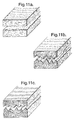
- Fig. 13 shows various possibilities of how four conveyor pairs can be arranged in principle.
- the adjustments according to Figs. 13b and 13c cannot be made with the compression unit according to Figs. 8 to 10.
- An arrangement of the roller groups 31', 31'', 33', 33'', 35', 35'', 37' , 37'' according to Fig. 13d is advisable, for example, if light products are to be made.
- the optimisation unit 19 comprising a plurality of conveyor pairs is followed by the optional multi-ply unit 21, which in the exemplified embodiment illustrated is in the form of a dual density device.
- This comprises a separating device 41, for example, a band saw or a band knife, which is shown only in outline in Fig. 7 for separating the compressed fleece 20 into two webs 43 and 45.
- the multi-ply unit 21 also comprises conveyors 47, 49, 50 and 51, e.g. conveyor belts, which fix the compressed sub-webs 43, 45 in thickness. Any gaps occurring for geometric reasons between the separating device and, for example, the conveyor belt 49 or 50 can be bridged where possible by guide plates. These prevent the fleece web 43, which is compressed to varying degrees, from breaking out.
- the separating device 41 and following conveyor is preferably adjustable as to height. This enables the fleece emerging from the compression unit 19 to be cut into lower and upper webs 43, 45 of practically any thickness.
- the separating device 41 and the conveyor belt 49 can also be displaced independently of one another and upwardly to an extent such that they are disposed outside the range of transport of the fleece.
- the conveyor belt 49 then serves as a hold-down belt.
- the apparatus 11 can be used optionally for the production of single-ply or multi-ply boards. Basically, a plurality of separating devices and corresponding hold-down belts can be provided to enable boards to be produced with three or even more layers. Also, the distance between the upper and lower rollers is adjustable so that outer layers of different thicknesses can be made.
- the conveyor pairs 53, 54 provided after the conveyors 50, 51 serve for thickness and longitudinal compression of the upper web 45.
- the conveyor pairs 53, 54 preferably comprise rollers S5, which are combined in each case to form upper and lower roller groups with three rollers in each case.
- the conveyor pairs 53, 54 are each drivable at different circumferential speeds so that the elongations which may occur as a result of thickness compression can be compensated by subsequent longitudinal compression. Also, the distance between the upper and lower rollers is adjustable so that outer layers of different thicknesses can be made.
- Conveyor belts, chutes and/or guide plates combine the compressed web 45' with the lower web 43. In most cases a hold-down belt for the highly compressed web 45' can be dispensed with.
- a metering device 57 for a binder is provided in the zone where the webs 43, 45 meet. With this arrangement it is possible to apply binder to the contact surfaces of the upper and/or lower webs 43, 45' so that a better bonding is obtained after curing of the binder. In most cases, particularly if any elongations occurring have been compensated previously, a metering device 57 can also be dispensed with.
- Feed belts 59, 61 and feed rollers 63, 65 press the combined webs 43, 45' together and transport the same into the curing oven 25.
- the circumferential speeds of the feed belts 59, 61 and feed rollers 63, 65 are advantageously individually adjustable so that compression or decompression of the compressed webs 43, 45' can be effected as required.
- At least the feed rollers 63, 65 are preferably coolable.
- Air-permeable conveyor belts 67, 67' are preferably provided in the curing oven 25. The belts 67, 67' hold the webs 43, 45' together during the curing process and thus substantially determine the nominal thickness of the finished boards.
- the belts 67, 67' like the conveyors 59, 61, 63, 65, are vertically adjustable and can thus be adjusted to the fleece thicknesses coming from the multi-ply unit 21 or the compression unit 19.
- the production of the multi-ply board can be carried out as follows: the primary fleece delivered from a collecting chamber (not shown) and provided with binder and, in the case of rock wool fibres usually of a weight of about 200 - 800 g/m2, preferably 200 400 g/m2, with an approximately average thickness of 15 - 20 mm, or frequently up to 75 mm, is fed to the pendulum belt 13.
- the latter deposits the primary fleece on the continuously advancing collecting belt 15.
- a larger or smaller number of fleece layers is formed on the belt 15 in the vertical direction.
- the number of layers is selected according to the required board properties, e.g. weight, compressive strength etc., of the end product.
- the number of layers also depends on the fibre formulation, i.e. the individual fibre processing stages between the fibre production unit and the curing oven 25. Usually 2 to 40 to 50 layers are deposited on the collecting belt 15.
- Depositing the primary fleece 26 by means of the pendulum belt 13 not only provides good transverse distribution of the fibre material on the collecting belt 15, but also contributes to uniform fibre orientation and a certain homogenisation.
- the fibre orientation can be further controllably influenced by changing the direction of the pendulum movement.
- the deposited fleece is subjected to a precompression in the precompression stage 17.
- the precompression is usually such that the fleece can be engaged by the rollers of the first conveyor pair (required nominal thickness plus at maximum approximately 40% of the roller diameter).
- Some deflection of the fleece after precompression is desirable so that, on entry into the compression unit, sufficient adhesion between the fleece and the rollers is achieved to give the required reorientation of the fibres. Since, in the case of products having a density of less than approximately 80 to 90 kg/m3 the expansion forces prevailing in the fleece during longitudinal compression are much lower, a moderate thickness compression in addition to the longitudinal compression is usually necessary in the production of these products in order to set the required tension and avoid undesirable pleating at the fleece surface.
- the fleece surfaces In the case of doubling, i.e. when the primary fleece is deposited in layers, the fleece surfaces have steps showing to varying degrees. These steps can be at least partially evened out in the precompression stage 17, by driving the upper belt 29 at a slightly higher speed than would be necessary for further transport.
- the partially smoothed fleece can be subjected to further smoothing in the optimisation unit 19.
- the first and second conveyor pairs can be disposed so as to be out of alignment. It is also possible for any other pairs of conveyors to be disposed out of alignment.
- the out-of-alignment arrangement subjects the conveyed fleece 20 to a bending or transverse deflection, which can effect smoothing of the fleece surfaces. The smoothing effect can be enhanced if the second conveyor pair runs somewhat more slowly than the first.
- a longitudinal compression of 2:1 to 6:1 (corresponding to the circumferential speeds of the first and the last conveyor pairs 31 and 37) is effected in the compression unit 19 substantially with a roller spacing corresponding to the nominal thickness of the board being produced (i.e. compaction by longitudinal compression without thickness compression).
- a longitudinal compression together with simultaneous moderate thickness compression may be advantageous.
- each two conveyor pairs 31, 33 and 35, 37 can be driven jointly by one drive.
- rollers are preferred, because the tendency to pleating at the fleece surfaces is relatively minor, even with a considerable degree of longitudinal compression.
- the fleece can be greatly longitudinally compressed with rollers 39 without appreciable pleating at the fleece surface.
- One possible explanation for this is that there is only a slight adhesion between the rollers and the fleece.
- the rollers also promote the reorientation of the fibres, since the fleece can expand somewhat between the rollers in each case but without pleating.
- Separation of the fleece 20 is effected by a band saw or a band knife in manner known per se.
- the upper web 45 with the optimised fibre structure is then subjected to a thickness and longitudinal compression. In this, the fibres of the upper layer 45 are further compacted by the thickness and subsequent longitudinal compression.
- the thickness-compressed web 45' is then returned to the continuously moving lower web 43.
- the compressed fleece 43, 45', more particularly the web 43 under tension, is guided between the compression stage 19 and the curing oven 25 by the conveyors 47, 49, 59, 61, 63, 65, for example belts, chains or roller systems, preferably conveyor belts, in order to prevent any break-out or bulging.
- the conveyors 47, 49, 59, 61, 63, 65 for example belts, chains or roller systems, preferably conveyor belts, in order to prevent any break-out or bulging.
- the binder in the fleece is cured. Curing of the binder takes place at temperatures between 180 and 300°C, preferably at about 200 to 250°C.
- the binder also ensures a firm bonding between the two webs 43, 45' of low and high gross density.
- the contact points thereof can be provided with a solid or liquid adhesive (metering device 57) on the multi-ply unit before being combined.
- the bonding between the two webs 43 and 45' can be improved if the webs are contracted somewhat before the curing oven 25, preferably in a ratio of 1.1:1 to 2:1. Depending on the degree of contraction, this may result in some pleating of the webs. The contraction results in the contact surfaces increasing in size and the adhesion/felting of the webs can thus be improved.
- the fleece or felt is longitudinally compressed preferably in a single stage.
- the apparatus can also be so operated that a plurality of compression zones or a continuous compression zone form during the compression.
- the weight in boards produced by the new process can be reduced by up to 25 to 40% for otherwise substantially identical mechanical properties.
- the tensile strength perpendicularly to the board plane is greatly improved, this being evident from the highly structured breaking zone (Figs. 11b and 11c).
- Products according to the invention can be used for any of the conventional purposes of synthetic fibres, e.g. for boards, webs, used for thermal insulation, fireproofing and fire protection or soundproofing and sound control, or in suitable form in horticulture as a growth medium.
Abstract
Description
- This invention relates to a process and apparatus for the production of a mineral fibreboard.
- Various improvements in the production of mineral fibreboards have been disclosed in recent years. A substantial improvement to the properties of mineral fibreboards can be obtained, for example, by reorienting the fibres in the production process so that they are aligned predominantly perpendicularly to the large surfaces of the board. The compressive strength and the tensile strength perpendicularly to the board plane can be substantially increased as a result.
- Various processes are known whereby the fibres are reorientated such that the product acquires a pleated configuration but improved performance is usually obtained when the final product is substantially free of pleats. There have been various disclosures of processes for length compression of a fibre web either to form a pleated or a substantially unpleated product. See for instance DE-A-1,635,620, EP 133,083, US 4,567,078, WO91/14816 and WO94/16164.
- It is already known to split a web in the thickness direction into sub-webs, to compact one of them and then recombine them and cure them, for instance from CA-A-1057183 and EP-A-277,500. Such processes have various disadvantages. For instance the bottom web is often only precompressed so that the final product has relatively low compressive strength. The processes also have the disadvantage that the bottom layer only undergoes slight compaction and substantially no rearrangement of fibre orientation.
- In WO88/00265, WO92/13150 and WO94/16162 the web is longitudinal compressed before the web is split into two layers.
- According to the invention we provide a continuous process for the production of a two-ply or multi-ply bonded mineral fibreboard from a mineral fibre fleece by longitudinal precompression of the fleece in a compression unit, feeding the precompressed fleece to a separating device, separating the fleece by means of the separating device into two or more sub-webs, compressing at least one sub-web in the direction of the thickness, followed by combining the sub-webs and transporting the same on to a bonding station in which the fleece is bonded, characterised in that the break-out of the tensioned sub-webs between the compression unit and the bonding station is prevented by means that prevent break out. The means that prevent break out can include constraining means.
- Thus, in the process of the invention the thickness and longitudinally compressed fleece is divided into two or more sub-webs parallel to the larger surfaces, while to prevent any deformation in the thickness direction the sub-webs are each held at the opposite large surfaces. At least one of the webs is compressed in the direction of the thickness and/or longitudinally with the sub-webs are then combined and subsequently bonded. Multi-ply products can be produced by this process.
- Although the adhesion of the sub-webs by the curing of the binder is normally sufficient, the contact surfaces of the sub-webs can be sprayed or impregnated with binder before being combined. Basically, the combined webs held together by suitable means can be thickness compressed once again. Advantageously, however, the webs are longitudinally compressed before bonding. The longitudinal compression can be effected in a ratio of 1.1:1 to maximum 2:1. The contact surfaces can be increased in size by a final longitudinal compression so that the bonding of the sub-webs is improved.
- In a preferred process we provide a process for the continuous production of a mineral fibre board having two or more layers of different densities by precompressing a fibre felt, feeding the precompressed felt to a separating device, separating the felt into two or more sub-webs, compressing at least one sub-web in the direction of the thickness, followed by combining the sub-webs, and transporting the same on to a bonding station in which the felt is bonded, characterised in that the fibre felt is longitudinally compressed before the separating device in a compression unit without compression in the direction of the thickness in a continuous compression zone in which the nominal thickness of the product is maintained, and in that break-out of the tensioned sub-webs between the compression unit and the bonding station is prevented by constraining means.
- We also provide novel apparatus for the continuous production of a bonded mineral fibreboard from a mineral fibre fleece comprising means disposed consecutively in the conveying direction F for precompressing the fleece, first transport means for transporting the fleece to a separating device, a separating device for separating the fleece into two or more sub-webs, means for compressing at least one sub-web in the direction of the thickness, second transport means for subsequently combining the sub-webs and transporting the same on to the bonding station in which the fleece is bonded, a bonding station for bonding the compressed fleece characterised in that the first transport means form a compression unit which comprises at least two conveyor pairs disposed consecutively in the conveying direction, and in that means are provided to prevent break-out of the tensioned sub-webs between the compression unit and the bonding station.
- The processes and apparatus of the invention differ from some known processes and apparatus essentially in that the precompressed web is compressed further in the thickness and/or longitudinal direction, particularly the longitudinal direction, by a compression unit, so that the sub-webs produced can already have relatively high densities and different fibre structures before being split. The advantage of this, for example, in the case of two-ply boards, is that the lower-density layer, unlike conventional boards, has a better compressive strength and tensile strength perpendicularly to the large surfaces. A specific tensile and compressive strength can therefore be achieved with reduced use of material, particularly a smaller quantity of fibre, compared with the known processes.
- In order that the fleece webs under tension should not break-out or pleat between the compression unit and the bonding station, suitable hold-down means and/or conveyors are advantageously provided to hold the fleece webs at the large surfaces.
- To form a highly compacted top layer, at least one of the split sub-webs can be thickness-compressed. A higher piercing strength can be obtained in this way. Advantageously, however, the one thickness-compressed sub-web can also be longitudinally compressed. Rolling the reoriented fibres flat by thickness compression may necessitate compensation of the resulting elongation.
- To improve the bond between the sub-webs, the contact surfaces of the sub-webs can additionally be provided with binder before being combined. In many cases, however, the quantity of binder initially applied to the fibres is already sufficient to achieve a good bond between the sub-webs on curing of the binder. Another possibility for improving the bond between the sub-webs is to compress the combined webs in length before curing. By contracting the webs, e.g. in a ratio of 1.1:1 to a maximum 2:1 it is possible to enlarge the contact surfaces and hence obtain a better bond between the layers.
- One problem in connection with the continuous production of two-ply or multi-ply products may be soiling of the band knife used by the binder adhering to the fibres. One advantageous variant of the process therefore proposes continuously cleaning the separating device. This can be effected, for example, by means of a solvent jet, e.g. water, directed to the cutting edge of the band knife.
- Advantageously, the longitudinal compression is effected by passing the fleece through a compression unit comprising a plurality of conveyor pairs disposed consecutively in the direction of conveyance, the speed of at least one conveyor pair being less than that of the preceding conveyor pair. Advantageously, the precompressed fleece is longitudinally compressed in at least one stage. Longitudinal compression enables the fibres to be reoriented so that, in particular, the compressive strength and tensile strength perpendicularly to the large surfaces are improved. As a result of the fibre structure optimisation it is possible to reduce the resources used.
- Advantageously, for the production of products having a pleated fibre structure, the spacing of the opposite conveyors of a conveyor pair is set to approximately 0.5 to 0.1 times the spacing of the following conveyors, the conveying path defined by the two conveyor pairs being disposed substantially in alignment and the circumferential speed at least of the directly following pair being less than the circumferential speed of the preceding conveyor pair. In this way it is possible to produce a fleece web having a pleated fibre structure (Fig. 2).
- Advantageously, before entry to the compression unit, the fleece is already compressed to approximately 0.8 to 1.5 times, preferably 0.9 to 1.3 times the nominal thickness and quite particularly preferably to the approximate nominal thickness of the finished product, so that there is substantially only a longitudinal compression by the conveyors of the compression unit. The longitudinal compression can take place in a continuous compression zone in which the nominal thickness of the product is maintained. Surprisingly, a very homogeneous gross microdensity can be obtained if the fleece is already precompressed to approximately the nominal thickness of the finished product before the compression unit and is then only longitudinally compressed. The mineral fibre fleece is advantageously compressed in length by a factor of 2 to 10, preferably by a factor of 2.5 to 5 and quite particularly preferably by a factor of about 2.5 to 3.5. In some cases, for example when the density of the bottom sub-web of the finished product is to be less than approximately 100 kg/m3, a simultaneous longitudinal and thickness compression may be indicated. The degree of thickness compression is advantageously less than 2 and preferably less than 1.5.
- Although the conveyors of the compression unit may be conveyor belts, the conveyors in a particularly preferred embodiment are constructed as roller conveyors. Unlike conveyor belts, rollers have the advantage that the fleece is repeatedly expanded and compressed by the rollers during compression. As a result the products surprisingly have a very homogeneous gross microdensity (density distribution in a small unit volume) and very good mechanical properties, such as compressive, piercing and tensile strength in products of significantly reduced weight compared with conventional products. The fibres are uniformly felted and no preferential fibre orientation can be detected (Fig. 11). On an enlarged scale it has been found that the random-orientation fibres are partly arranged in a corrugated pattern. This type of fibre structure is designated a corrugated fibre structure by the inventors. Another desirable effect is the compaction of the fleece web surfaces which is possible by means of rollers.
- Although the individual rollers can each be individually controllable, in one advantageous embodiment each roller conveyor comprises in each case two opposite groups of at least two rollers in each case, the rollers of a conveyor each being driven at the same circumferential speed. Since the rollers are combined in groups of at least two rollers, the compression unit and its control are greatly simplified.
- Advantageously, the fleece is stretched in the conveying direction before the separating device. Expanding the fleece can prevent unwanted pleating or breaking-out of the fleece web, e.g. on transition from the compression unit to the separating device.
- The fleece may consist of glass wool, rock wool or other synthetic fibres. Preferably, however, the fleece consists essentially of rock wool fibres and contains non-cured binder. The binder content by weight can be between approximately 0.7 and 4%. The binder is preferably curable in a curing oven. Bonding of the fleece can, however, be effected by needling or felting.
- Advantageously, mineral fibres of an average length between approximately 0.3 and 50 mm, preferably between approximately 0.5 and 15 mm and of a thickness between approximately 1 to 12 µm, preferably between approximately 3 and 8 µm are used. However, it is also possible to use mineral fibres of an average length of between approximately 1 and 10 mm, preferably between approximately 2 and 6 mm and of an average thickness of between approximately 2 to 10 µm, preferably between approximately 3 to 7 µm. The average length of rock wool fibres, which are usually shorter than glass fibres, is as a rule 2 to 4 mm and the average diameter is 3 to 4 µm.
- Advantageously, during the deposition of the fleece on the conveyor the predominant orientation of the fibres is changed or partially evened out. This can be effected, for example, by means of a spinning member adapted to swing at an angle to the direction of transport, or by means of air curtain. The density distribution of the fleece can thus be improved and the fibre orientation changed, this having a favourable effect on the mechanical properties of the resulting products. Advantageously, the primary fleece is deposited on the collecting belt in layers by means of a pendulum belt adapted to swing at an angle to the transport direction. In this way the fibres are partially reoriented and the homogeneity (transverse distribution) of the fleece deposited on the collecting belt can be improved.
- Advantageously, 2 to approximately 60 layers, preferably between 2 and 40 to 50 layers, are deposited one above the other. This results in some reorientation of the fibres.
- The fleece can, for example, be deflected transversely of the direction of transport, while a compression, more particularly longitudinal compression, can take place at the same time.
- The present invention also relates to an apparatus according to characterising features of claim 14. The apparatus according to the invention is characterised in that an additional compression unit is provided between the precompression stage and the separating device in order to compress the fleece further in the thickness and/or longitudinal direction, more particularly in the longitudinal direction, and reorient the fibres. Conveyor belts serve to maintain the fibre structure once obtained and prevent any deflection or break-out of the tensioned fleece.
- Other advantageous embodiments are indicated in the sub-claims. According to a preferred exemplified embodiment, at least the separating device and the following hold-down device are adjustable independently of one another perpendicularly to the belt surface in the region of the multi-ply unit, so that the apparatus can be used selectively for the production of single ply or multi-ply products.
- Advantageously, the means for compressing the at least one sub-web comprise at least two independently driven conveyor pairs. In this way the split sub-web can also be compressed in length. The conveyor pairs are advantageously roller conveyors, the roller spacing being adjustable. As a result the sub-webs can be compressed both in thickness and in length.
- Advantageously, the bonding station is a curing oven, coolable feed rollers being provided before the said oven. In this way any adhesion of the binder to the rollers can be prevented and clogging obviated. In one advantageous embodiment, the circumferential speeds of the transport means between the separating device and the bonding station and the circumferential speed of the conveyor belts in the oven are individually adjustable so that, for example, compression or decompression can also be effected before the curing oven.
- The longitudinal precompression can be conducted as described and claimed in EP-A-889,981, from which the present application is divided.
- Exemplified embodiments of the invention are described below with reference to the drawings wherein:
- Fig. 1 shows a mineral wool product produced by thickness compression and having a fibre orientation substantially parallel to the surface.
- Fig. 2 shows a pleated product comprising a majority of fibres disposed perpendicularly to the surfaces.
- Fig. 3 shows a two-ply product, the upper layer of which has increased density.
- Fig. 4 shows a product with substantially homogeneous density and random-orientation fibres.
- Fig. 5 shows a product in which a layer having random-orientation fibres is combined with a layer of increased density.
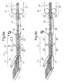
- Fig. 6 is a simplified view of an apparatus for the production of a single-ply mineral fibreboard a) in a continuous process and in a continuous compression zone respectively and b) in a single-stage process.
- Fig. 7 is a diagram showing the principle of an apparatus for the continuous production of a single-ply or multi-ply mineral fibreboard of different densities; a) in a continuous process and in a continuous compression zone respectively and b) in a single-stage process.
- Fig. 8 is a front elevation of a compression unit in detail.
- Fig. 9 is a side elevation of the compression unit of Fig. 8.
- Fig. 10 is a plan view of the compression unit of Fig. 8.
- Fig. 11 shows the breaking zone of a) a board having a substantially parallel fibre orientation and b) and c) rock wool boards made by the new process and pulled apart perpendicularly to the board plane.
- Fig. 12 is a perspective section through a two-ply board, the fibre structure being shown on an enlarged scale and Fig. 13 is a diagram showing various possible arrangements of four conveyor pairs disposed consecutively in the conveying direction.
-
- Figs. 1 to 5 illustrate the fibre orientations frequently occurring in softboards. Boards having fibres disposed parallel to the surface (Fig. 1) have comparatively poor mechanical properties. To compensate for the disadvantages, the fibres are frequently strengthened with binder and the density increased.
- Products having fibres arranged perpendicularly to the surface can be obtained if a board of the kind shown in Fig. 1 is cut into strips, the strips are turned through 90° and are then bundled. This type of manufacture is complex and correspondingly uneconomic. According to another type of manufacture, the fleece is pleated (pleating process, Fig. 2). These products have a substantially better compressive and tensile strength perpendicularly to the board plane than boards of the kind shown in Fig. 1. Boards having pleated fibres can bend and can therefore be used for insulating pipes or for lining curved areas. A disadvantage, on the other hand, is that these products tend to break along the pleats, and the piercing strength is inadequate. Another disadvantage of the known products of this kind is that there may be relatively considerable differences in density within the board.
- Fig. 3 shows a two-ply product, the top layer of which has an increased density. These products are suitable for applications requiring high tread strength or enhanced surface protection. As a result of the increased density of the top layer the average density can be reduced.
- Fig. 4 shows a product with substantially isotropic fibre orientation with a substantially random fibre orientation. These products have excellent mechanical properties, such as high compressive, tread, and piercing strength, and high tensile strength perpendicularly to the board plane. They do not break and their thermal conductivity is substantially the same as the products shown in Fig. 1. Generally, these products are lighter than comparable products having substantially parallel fibres for comparable or improved mechanical properties.
- Fig. 5 shows a product in which the advantages of increased density of the top layer and of the fibre structure shown in Fig. 4 are combined. The object of the invention is particularly further to improve the properties of products of the kind shown in Figs. 4 and 5.
- The apparatus 11' shown in Fig. 6 for performing a suitable precompression process suitable for use in the invention comprises, as considered in the conveying direction F, a precompression stage 17', an optimisation or compression unit 19' adjoining the precompression stage 17' and consisting of two conveyor pairs 30, 32 for compressing the felt or fleece, and also a
conveyor belt 40 and a hold-downbelt 42 andfeed rollers oven 25. Finally,conveyor belts 67, 67' are provided in the curingoven 25 to transport the compressed fleece through the oven and hold the same at the opposite large surfaces during curing of the binder. - The precompression stage 17' consists of a
lower conveyor belt 27 and apressing belt 29. By means of the precompression stage 17', the primary fleece deposited preferably in layers on a collectingbelt 15 is precompressed to such an extent that the fleece denoted byreference 20 can be introduced into the compression unit 19'. For this purpose thepressing belt 29 is adjustable as to height. - The conveyor pairs 30, 32 of the compression unit 19' consist of upper and lower roller groups 30', 30' ' and 32', 32'' each consisting of six
rollers 39. The upper and lower roller groups 30', 30''; 32', 32'' each have a separate drive (not shown in detail) so that the conveyors can be driven at different speeds respectively. Also, the upper roller group 30', 32' are adjustable as to height, so that the apparatus 11' can be used for the production of products of different thicknesses. The distance between the upper and lower roller groups 30', 30'', 32', 32' ' is preferably identical. - To perform this process, the fleece is precompressed in the precompression stage to approximately the nominal thickness of the finished product and then longitudinally compressed with a conveyor spacing corresponding approximately to the nominal thickness of the finished product. In these circumstances the
conveyor 30 is driven at a first speed and theconveyor 32 at a second speed which is usually not more than half the first speed so that a corresponding longitudinal compression of thefleece 20 results. In principle, another conveyor could be provided in order to expand the fleece somewhat after longitudinal compression. The latter step can prevent the highly compressed fleece from pleating or breaking out in the upward direction on transport into the curingoven 25. - The
compression unit 19 is followed by aconveyor belt 40 and a hold-downdevice 42 in order to constrain thecompressed fleece 20 against breaking out, ie buckling upwards off theconveyor 40. The hold-downdevice 42 consists of an uncoilable relatively heavy belt which is placed on the conveyed fleece web. The belt can be additionally loaded by applied weights.Feed rollers oven 25 and are preferably coolable. Advantageously, the distances between the lower and upper roller groups are each set to approximately the nominal thickness of the end product. This has the advantage that once the fibre orientation has been set in thecompression unit 19 it is no longer changed. - The precompression apparatus shown in Fig. 7 differs from that shown in Fig. 6 basically in that the
compression unit 19 has four conveyors each with four rollers. A multi-ply unit is also provided, in accordance with the invention, and is used for the production of multi-ply boards, and can in principle also be used together with the apparatus 11' shown in Figures 6a and 6b. For simplification, the same references are used in the following description as in the description of the apparatus 11' for like parts. - The apparatus shown in Fig. 7 for the production of mineral fibre boards comprises essentially, arranged consecutively in the direction of conveyance F, a
pendulum belt 13 and a collectingbelt 15 for the respective deposition and reception of fibres produced by a fibre production unit (not shown in detail), and aprecompression stage 17 and an optimisation orcompression unit 19 for forming a felt orfleece 20 having optimised fibre orientation and homogeneity. Thecompression unit 19 for optimising the compression is followed by an optionalmulti-ply unit 21 which can be used for the production of multi-ply mineral fibre boards. Themulti-ply unit 21 is followed by transport means 23 which hold the compressed fleece clamped at the opposite large surfaces and feed the same to a bonding station, e.g. a curingoven 25. - The above-mentioned fibre production unit serves for the continuous production of fibres by one of the known methods, e.g. the cascade spinning process. The fibres produced, also termed the "primary fleece", are sprayed (not shown) with a binder and pass by means of a conveyor (not shown) to the
pendulum belt 13. The latter belt is situated above the collectingbelt 15 and swings transversely to the direction of transport of the collectingbelt 15. A different orientation of the pendulum movement, e.g. in the transport direction, is however also possible. As a result of the pendulum movement, theprimary fleece 26 is deposited as cross-laps, as will be seen from Fig. 7, on the forwardly moving collectingbelt 15, depending on the speed of the latter and the frequency of the pendulum movement. Other means, for example gas jets, are however possible for the production of the most random possible fibre orientation on the collecting belt. As a result of the advance movement of the collectingbelt 15, the orientation of the fibres is predominantly at an angle to the direction of transport. Viewed from above, the fibres of two superposed fleece layers extend substantially crosswise. - The
precompression stage 17 consists of alower conveyor belt 27 and apressing belt 29. The latter is adjustable as to height so that thefleece 26 can be precompressed to different degrees. Theprecompression stage 17 provides precompression and a certain homogenisation of the relativelyloose fleece 20 before the same is introduced into theoptimisation unit 19. The twobelts - According to the exemplified embodiment shown, the
optimisation unit 19 consists of a plurality of conveyors or conveyor pairs 31, 33, 35, 37. Eachpair rollers 39. The clearance between the individual roller groups 31', 31''; 33', 33''; 35', 35''; 37' , 37'' is adjustable. The roller groups are also adapted to be inclined relatively to one another preferably in the direction of transport. The latter property enables thefleece 20 to be continuously compressed in thickness or be decompressed on passage through aconveyor pair - A number of different formulations for the fleece optimisation can be obtained as a result of the possibility of adjusting the distance between the opposite roller groups and their speeds. In this way the product properties can be quite different. Also, because of these adjustment facilities, the fibre structure can be controllably optimised and, for example, undesirable pleating at the fleece surface can be prevented.
- At least the lower and upper roller groups 31'' and 31' respectively of the
first conveyor pair 31 are adjustable as to height. This enables the fleece to be subjected to bending, as shown in Fig. 7, for example in order to smooth and compact the fleece surface. - The upper and lower roller groups 31', 31''; 33', 33''; 35', 35''; 37', 37' ' of the conveyor pairs 31, 33, 35, 37 each have a separate drive not shown in detail in Fig. 7. The drives used are preferably infinitely variable within a specific range, so that, for example, the upper and lower roller groups can have different circumferential speeds. A slightly higher circumferential speed of the upper roller group is necessary, for example, if the same is disposed, not horizontally, but at an angle to the lower roller group.
- Figs. 8 to 10 show an exemplified embodiment of a
compression unit 19 in which the conveyors with the roller groups 31', 31''; 33', 33''; 35', 35''; 37', 37'' having therollers 39 are disposed on a supportingstructure 71. Chain wheels 115 (Fig. 10) are provided at one end of each of therollers 39. Each four or fiverollers 39 are interconnected by drive chains (not shown) and form a roller group. A drive 117', 117'', 117''', 117'''', 118', 118'', 118''', 118'''' is provided for each roller group. - The upper and lower roller groups 31', 31'' of the
first conveyor pair 31 considered in the direction of conveyance (Fig. 9, arrow F) are vertically adjustable. The vertical adjustment of the upper roller group 31' is effected by means of adrive member 81 which drives thespindles 73, 73' via theCardan shafts 77, 77'. - A
drive member 83 driving thespindles 75, 75' via theCardan shafts 79, 79' is used for the vertical adjustment of the bottom roller group 31''. - Unlike the first roller groups 31', 31'', the position of the remaining roller groups is either not adjustable (at the bottom) or adjustable only jointly (at the top). As will be seen particularly from Figs. 8 and 9, the rear bottom three rollers groups 33'', 35'', 37'' as considered in the direction of conveyance are disposed on a
stationary frame 85 while the upper three roller groups 33', 35', 37' are disposed on a verticallyadjustable frame 87. Thelatter frame 87 is vertically adjustable at the top part of the supportingstructure 71. Linear guides 93 at thecolumns 95, 95', 97, 97' provide vertical guidance of theframe 87. Adrive member 103 which by way of theCardan shafts spindles structure 71 is provided for vertical adjustment of theframe 87. - The upper roller groups 33', 35', 37', the last of which has 5
rollers 39, are disposed onsupport rails 105 pivotally connected to theframe 87 by thepivot 107. In the exemplified embodiment illustrated, the front end of therails 105 as considered in the direction of conveyance is connected to the verticallyadjustable frame 87 by another pair ofspindles 109, 109'. By adjustment of thespindles 109, 109' it is possible to swing the support rails 105 upwardly or downwardly out of the horizontal so that, for example, it is possible to form a path tapering in the direction of conveyance F. Thespindles 109, 109' are also interconnected viaCardan shafts 111, 111' so that here again onedrive 113 is sufficient to adjust them. - Fig. 13 shows various possibilities of how four conveyor pairs can be arranged in principle. The adjustments according to Figs. 13b and 13c, however, cannot be made with the compression unit according to Figs. 8 to 10. An arrangement of the roller groups 31', 31'', 33', 33'', 35', 35'', 37' , 37'' according to Fig. 13d is advisable, for example, if light products are to be made.
- The
optimisation unit 19 comprising a plurality of conveyor pairs is followed by the optionalmulti-ply unit 21, which in the exemplified embodiment illustrated is in the form of a dual density device. This comprises a separatingdevice 41, for example, a band saw or a band knife, which is shown only in outline in Fig. 7 for separating thecompressed fleece 20 into twowebs multi-ply unit 21 also comprisesconveyors compressed sub-webs conveyor belt fleece web 43, which is compressed to varying degrees, from breaking out. - The separating
device 41 and following conveyor is preferably adjustable as to height. This enables the fleece emerging from thecompression unit 19 to be cut into lower andupper webs device 41 and theconveyor belt 49 can also be displaced independently of one another and upwardly to an extent such that they are disposed outside the range of transport of the fleece. Theconveyor belt 49 then serves as a hold-down belt. Owing to the vertical adjustability, theapparatus 11 can be used optionally for the production of single-ply or multi-ply boards. Basically, a plurality of separating devices and corresponding hold-down belts can be provided to enable boards to be produced with three or even more layers. Also, the distance between the upper and lower rollers is adjustable so that outer layers of different thicknesses can be made. - Two conveyor pairs 53, 54 provided after the
conveyors upper web 45. The conveyor pairs 53, 54 preferably comprise rollers S5, which are combined in each case to form upper and lower roller groups with three rollers in each case. The conveyor pairs 53, 54 are each drivable at different circumferential speeds so that the elongations which may occur as a result of thickness compression can be compensated by subsequent longitudinal compression. Also, the distance between the upper and lower rollers is adjustable so that outer layers of different thicknesses can be made. - Conveyor belts, chutes and/or guide plates (not shown in detail) combine the compressed web 45' with the
lower web 43. In most cases a hold-down belt for the highly compressed web 45' can be dispensed with. Ametering device 57 for a binder is provided in the zone where thewebs lower webs 43, 45' so that a better bonding is obtained after curing of the binder. In most cases, particularly if any elongations occurring have been compensated previously, ametering device 57 can also be dispensed with. -
Feed belts feed rollers webs 43, 45' together and transport the same into the curingoven 25. The circumferential speeds of thefeed belts feed rollers webs 43, 45' can be effected as required. At least thefeed rollers permeable conveyor belts 67, 67' are preferably provided in the curingoven 25. Thebelts 67, 67' hold thewebs 43, 45' together during the curing process and thus substantially determine the nominal thickness of the finished boards. Thebelts 67, 67', like theconveyors multi-ply unit 21 or thecompression unit 19. - The production of the multi-ply board can be carried out as follows: the primary fleece delivered from a collecting chamber (not shown) and provided with binder and, in the case of rock wool fibres usually of a weight of about 200 - 800 g/m2, preferably 200 400 g/m2, with an approximately average thickness of 15 - 20 mm, or frequently up to 75 mm, is fed to the
pendulum belt 13. The latter deposits the primary fleece on the continuously advancing collectingbelt 15. Depending on the speed of thelatter belt 15 and the frequency of thependulum belt 13, a larger or smaller number of fleece layers is formed on thebelt 15 in the vertical direction. The number of layers is selected according to the required board properties, e.g. weight, compressive strength etc., of the end product. The number of layers also depends on the fibre formulation, i.e. the individual fibre processing stages between the fibre production unit and the curingoven 25. Usually 2 to 40 to 50 layers are deposited on the collectingbelt 15. - Depositing the
primary fleece 26 by means of thependulum belt 13 not only provides good transverse distribution of the fibre material on the collectingbelt 15, but also contributes to uniform fibre orientation and a certain homogenisation. The fibre orientation can be further controllably influenced by changing the direction of the pendulum movement. - The deposited fleece is subjected to a precompression in the
precompression stage 17. The precompression is usually such that the fleece can be engaged by the rollers of the first conveyor pair (required nominal thickness plus at maximum approximately 40% of the roller diameter). Some deflection of the fleece after precompression is desirable so that, on entry into the compression unit, sufficient adhesion between the fleece and the rollers is achieved to give the required reorientation of the fibres. Since, in the case of products having a density of less than approximately 80 to 90 kg/m3 the expansion forces prevailing in the fleece during longitudinal compression are much lower, a moderate thickness compression in addition to the longitudinal compression is usually necessary in the production of these products in order to set the required tension and avoid undesirable pleating at the fleece surface. - In the case of doubling, i.e. when the primary fleece is deposited in layers, the fleece surfaces have steps showing to varying degrees. These steps can be at least partially evened out in the
precompression stage 17, by driving theupper belt 29 at a slightly higher speed than would be necessary for further transport. - The partially smoothed fleece can be subjected to further smoothing in the
optimisation unit 19. To this end, for example, the first and second conveyor pairs can be disposed so as to be out of alignment. It is also possible for any other pairs of conveyors to be disposed out of alignment. The out-of-alignment arrangement subjects the conveyedfleece 20 to a bending or transverse deflection, which can effect smoothing of the fleece surfaces. The smoothing effect can be enhanced if the second conveyor pair runs somewhat more slowly than the first. - Preferably, a longitudinal compression of 2:1 to 6:1 (corresponding to the circumferential speeds of the first and the last conveyor pairs 31 and 37) is effected in the
compression unit 19 substantially with a roller spacing corresponding to the nominal thickness of the board being produced (i.e. compaction by longitudinal compression without thickness compression). In the case of lighter products, however, a longitudinal compression together with simultaneous moderate thickness compression may be advantageous. In the case of a single speed graduation, each two conveyor pairs 31, 33 and 35, 37 can be driven jointly by one drive. - Although conveyor belts can be used for compression, rollers are preferred, because the tendency to pleating at the fleece surfaces is relatively minor, even with a considerable degree of longitudinal compression. The fleece can be greatly longitudinally compressed with
rollers 39 without appreciable pleating at the fleece surface. One possible explanation for this is that there is only a slight adhesion between the rollers and the fleece. The rollers also promote the reorientation of the fibres, since the fleece can expand somewhat between the rollers in each case but without pleating. - This results in good compaction of the fibre felt in the interior and at the surface.
- Separation of the
fleece 20 is effected by a band saw or a band knife in manner known per se. Theupper web 45 with the optimised fibre structure is then subjected to a thickness and longitudinal compression. In this, the fibres of theupper layer 45 are further compacted by the thickness and subsequent longitudinal compression. The thickness-compressed web 45' is then returned to the continuously movinglower web 43. - The
compressed fleece 43, 45', more particularly theweb 43 under tension, is guided between thecompression stage 19 and the curingoven 25 by theconveyors - In the curing
oven 25 the binder in the fleece is cured. Curing of the binder takes place at temperatures between 180 and 300°C, preferably at about 200 to 250°C. The binder also ensures a firm bonding between the twowebs 43, 45' of low and high gross density. - To improve the adhesion of the
webs 43, 45', the contact points thereof can be provided with a solid or liquid adhesive (metering device 57) on the multi-ply unit before being combined. - Alternatively, or in addition, the bonding between the two
webs 43 and 45' can be improved if the webs are contracted somewhat before the curingoven 25, preferably in a ratio of 1.1:1 to 2:1. Depending on the degree of contraction, this may result in some pleating of the webs. The contraction results in the contact surfaces increasing in size and the adhesion/felting of the webs can thus be improved. - With the above-described apparatus according to the invention, the fleece or felt is longitudinally compressed preferably in a single stage. Alternatively, the apparatus can also be so operated that a plurality of compression zones or a continuous compression zone form during the compression.
-
- Board type Single-ply
- Fibre material Rock wool
- Board thickness 100 mm
- Gross density About 90 kg/m3
- Binder Modified phenolic resin
- Average fibre length From about 3 to 4 mm
- Average fibre diameter From 3 to 4 µ m
- Precompression Approximately nominal thickness
- Longitudinal compression 3 : 1
- Compressive strength at 10% deflection 0.035 N/mm2
- Pull-off strength 0.020 N/mm2
-
-
- Board type 2-ply
- Fibre material Rock wool
- Board thickness 100 mm
- Outer layer thickness About 20 mm
- Substrate thickness About 80 mm
- Average gross density About 90 kg/m3
- Outer layer gross density 155 kg/m3
- Substrate
gross density 75 kg/m3 - Binder Modified phenolic resin
- Average fibre length From about 0.5 to 10 mm
- Average fibre diameter From 3 to 6 µm
- Precompression Approximately 1.5 nominal thickness
- Thickness compression 1.8 : 1 to 1.1 : 1
- Longitudinal compression 3 : 1
- Compressive strength at 10%
- deflection 0.025 - 0.030 N/mm2
- Pull-off strength 0.013 - 0.018 N/mm2
-
-
- Board type 2-ply
- Fibre material Rock wool
- Board thickness 100 mm
- Outer layer thickness About 20 mm
- Substrate thickness About 80 mm
- Average gross density About 90 kg/m3
- Outer layer gross density 155 kg/m3
- Substrate
gross density 75 kg/m3 - Binder Modified phenolic resin
- Average fibre length About 3 to 4 mm
- Average fibre diameter From 3 to 4 µm
- Precompression Approximately 1.8 to 1.5 times nominal thickness
- Thickness compression 1.5 : 1.1 : 1
- Longitudinal compression 3 : 1
- Compressive strength at 10%
- deflection 0.025 - 0.030 N/mm2
- Pull-off strength
- (Delamination) 0.013 - 0.018 N/mm2
- Diameter of rollers used 80 mm.
-
- In comparison with boards having a non-optimised fibre structure and density, the weight in boards produced by the new process can be reduced by up to 25 to 40% for otherwise substantially identical mechanical properties. The tensile strength perpendicularly to the board plane is greatly improved, this being evident from the highly structured breaking zone (Figs. 11b and 11c).
- Products according to the invention can be used for any of the conventional purposes of synthetic fibres, e.g. for boards, webs, used for thermal insulation, fireproofing and fire protection or soundproofing and sound control, or in suitable form in horticulture as a growth medium.
Claims (20)
- A continuous process for the production of a two-ply or multi-ply bonded mineral fibreboard from a mineral fibre fleece by longitudinal precompression of the fleece in a compression unit (19), feeding the precompressed fleece (20) to a separating device (41), separating the fleece by means of the separating device (41) into two or more sub-webs (43, 45), compressing at least one sub-web (45) in the direction of the thickness, followed by combining the sub-webs (43, 45') and transporting the same on to a bonding station (25) in which the fleece is bonded, characterised in that break-out of the tensioned sub-webs (43, 45) between the compression unit (19) and the bonding station (25) is prevented by means (49, 50, 51, 59, 61, 63, 65) that prevent break out.
- A process according to claim 1 in which the means that prevent break out are constraining means selected from belts, chains, roller systems and guide plates.
- A process according to claim 1 or claim 2 in which the constraining means extend from the separating device to the position where one sub-web is compressed and from the separating device to the position where the sub-webs are combined.
- A process according to any of claims 1 to 3, characterised in that at least the one thickness-compressed sub-web (45) is longitudinally compressed.
- A process according to any of claims 1 to 4, characterised in that the contact surfaces of the sub-webs (43, 45) are provided with binder before being combined.
- A process according to any preceding claim, characterised in that the combined webs (44, 45') are longitudinally compressed before bonding.
- A process according to any preceding claim, characterised in that the separating device (41) is continuously cleaned.
- A process according to any preceding claim, characterised in that the fleece is longitudinally compressed before the separating device in a compression unit in a continuous compression zone or in stages substantially without thickness compression taking place.
- A process according to any preceding claim characterised in that before entering the compression unit (21) the fleece is precompressed to approximately 0.8 to 1.5 times, preferably 0.9 to 1.3 times the nominal thickness of the finished product.
- A process according to claim 8 or claim 9 in which the compression is effected in one stage.
- A process according to any preceding claim in which the fleece is compressed to approximately the nominal thickness of the finished product at the latest by the last conveyor.
- A process for the continuous production of a mineral fibre board having two or more layers of different densities by longitudinally precompressing a fibre felt in a compression unit, feeding the precompressed felt to a separating device (41), separating the felt into two or more sub-webs (43, 45), compressing at least one sub-web (45) in the direction of the thickness, followed by combining the sub-webs (43, 45') and transporting the same on to a bonding station (25) in which the felt is bonded, characterised in that the longitudinal compression of the fibre felt is conducted in a compression unit (19) without compression in the direction of the thickness in a continuous compression zone in which the nominal thickness of the product is maintained, and break-out of the tensioned sub-webs (43, 45) between the compression unit (19) and the bonding station (25) is prevented by constraining means.
- A process according to any preceding claim in which the longitudinal compression imparts a pleated structure to the precompressed fleece.
- Apparatus for the continuous production of a bonded mineral fibreboard from a mineral fibre fleece comprising means (27, 29) disposed consecutively in the conveying direction F for precompressing the fleece, first transport means (19) for transporting the fleece to a separating device (41), a separating device (41) for separating the fleece into two or more sub-webs (43, 45) means for compressing at least one sub-web (45) in the direction of the thickness, second transport means (23) for subsequently combining the sub-webs (43, 45') and transporting the same on to the bonding station (25) in which the fleece is bonded, characterised in that the first transport means (19) form a compression unit which comprises at least two conveyor pairs (31, 33, 35, 37) disposed consecutively in the conveying direction, and means (49, 50, 51, 59, 61, 63, 65) are provided to prevent break-out of the tensioned sub-webs (43, 45) between the compression unit (19) and the bonding station (25).
- Apparatus according to claim 14 in which the constraining means extend from the separating device to the means for compressing at least one sub-web and from the separating device to the second transport means.
- Apparatus according to claim 14 or claim 15 in which the constraining means are selected from belts, chains, roller systems and guide plates.
- Apparatus according to any of claims 14 to 16, characterised in that means (57) are provided to provide the sub-webs with binder before they are re-combined.
- Apparatus according to any of claims 14 to 17, characterised in that the separating device (41) consists of a band knife or a band saw.
- Apparatus according to any of claims 14 to 18, characterised in that a cleaning device is provided for the continuous or intermittent cleaning of the band knife or band saw.
- Apparatus according to any of claims 14 to 19, characterised in that at least the separating device (41) and the following hold-down device (49) are vertically adjustable in the region of the multi-ply unit (21).
Priority Applications (2)
| Application Number | Priority Date | Filing Date | Title |
|---|---|---|---|
| SI9730780T SI1111113T1 (en) | 1996-03-25 | 1997-03-24 | Process and apparatus for the production of a mineral fibreboard |
| EP08007764A EP1942217A3 (en) | 1996-03-25 | 1997-03-24 | Apparatus for the production of a mineral fibreboard |
Applications Claiming Priority (7)
| Application Number | Priority Date | Filing Date | Title |
|---|---|---|---|
| CH00768/96A CH691816A5 (en) | 1996-03-25 | 1996-03-25 | Process and apparatus for producing mineral fibreboard |
| CH76896 | 1996-03-25 | ||
| CH216796 | 1996-09-02 | ||
| CH02169/96A CH691960A5 (en) | 1996-09-02 | 1996-09-02 | Process and apparatus for producing mineral fibreboard |
| CH216796 | 1996-09-02 | ||
| CH216996 | 1996-09-02 | ||
| EP97914299A EP0889981B1 (en) | 1996-03-25 | 1997-03-24 | Process and apparatus for the production of a mineral fibreboard |
Related Parent Applications (1)
| Application Number | Title | Priority Date | Filing Date |
|---|---|---|---|
| EP97914299A Division EP0889981B1 (en) | 1996-03-25 | 1997-03-24 | Process and apparatus for the production of a mineral fibreboard |
Related Child Applications (1)
| Application Number | Title | Priority Date | Filing Date |
|---|---|---|---|
| EP08007764A Division EP1942217A3 (en) | 1996-03-25 | 1997-03-24 | Apparatus for the production of a mineral fibreboard |
Publications (3)
| Publication Number | Publication Date |
|---|---|
| EP1111113A2 true EP1111113A2 (en) | 2001-06-27 |
| EP1111113A3 EP1111113A3 (en) | 2003-09-03 |
| EP1111113B1 EP1111113B1 (en) | 2008-05-14 |
Family
ID=27172403
Family Applications (3)
| Application Number | Title | Priority Date | Filing Date |
|---|---|---|---|
| EP97914299A Revoked EP0889981B1 (en) | 1996-03-25 | 1997-03-24 | Process and apparatus for the production of a mineral fibreboard |
| EP01102183A Expired - Lifetime EP1111113B1 (en) | 1996-03-25 | 1997-03-24 | Process and apparatus for the production of a mineral fibreboard |
| EP08007764A Withdrawn EP1942217A3 (en) | 1996-03-25 | 1997-03-24 | Apparatus for the production of a mineral fibreboard |
Family Applications Before (1)
| Application Number | Title | Priority Date | Filing Date |
|---|---|---|---|
| EP97914299A Revoked EP0889981B1 (en) | 1996-03-25 | 1997-03-24 | Process and apparatus for the production of a mineral fibreboard |
Family Applications After (1)
| Application Number | Title | Priority Date | Filing Date |
|---|---|---|---|
| EP08007764A Withdrawn EP1942217A3 (en) | 1996-03-25 | 1997-03-24 | Apparatus for the production of a mineral fibreboard |
Country Status (14)
| Country | Link |
|---|---|
| EP (3) | EP0889981B1 (en) |
| AT (2) | ATE395452T1 (en) |
| AU (1) | AU2159897A (en) |
| BA (1) | BA98344A (en) |
| CZ (2) | CZ291481B6 (en) |
| DE (2) | DE69738694D1 (en) |
| DK (1) | DK1111113T3 (en) |
| EA (1) | EA000493B1 (en) |
| ES (2) | ES2166530T3 (en) |
| HU (2) | HU223013B1 (en) |
| PL (2) | PL184688B1 (en) |
| SI (2) | SI0889981T1 (en) |
| SK (2) | SK283915B6 (en) |
| WO (1) | WO1997036035A1 (en) |
Cited By (8)
| Publication number | Priority date | Publication date | Assignee | Title |
|---|---|---|---|---|
| WO2003018933A1 (en) * | 2001-08-23 | 2003-03-06 | Deutsche Rockwool Mineralwoll Gmbh & Co. Ohg | Method for the production of an absorber element from mineral wool |
| EP1571247A2 (en) * | 2003-12-19 | 2005-09-07 | Saint-Gobain Isover | Process for manufacturing mineral wool products, in particular singlelayered and multilayered products |
| EP1826335A1 (en) | 2006-02-28 | 2007-08-29 | Rockwool International A/S | Insulated façade system |
| EP2100992A1 (en) * | 2008-03-12 | 2009-09-16 | Paroc Oy Ab | Method and arrangement for improving the runnability of a continuous mineral fibre web |
| EP2180104A1 (en) | 2008-10-21 | 2010-04-28 | Rockwool International A/S | Facade insulation system |
| EP2281962B1 (en) | 2009-06-25 | 2017-04-05 | Knauf Insulation | Aerogel containing Composite Material |
| US10703668B2 (en) | 2011-09-30 | 2020-07-07 | Owens Corning Intellectual Capital, Llc | Method of forming a web from fibrous material |
| EP3564423B1 (en) | 2018-04-30 | 2020-08-12 | Betek Tasyunu Sanayi Ve Ticaret A.S. | Process for the manufacture of mineral wool panels made of two or more layers having different densities |
Families Citing this family (17)
| Publication number | Priority date | Publication date | Assignee | Title |
|---|---|---|---|---|
| ES2166530T3 (en) | 1996-03-25 | 2002-04-16 | Rockwool Int | PROCEDURE AND APPLIANCE FOR THE PRODUCTION OF A MINERAL FIBER BOARD. |
| DE19860040A1 (en) * | 1998-12-23 | 2000-06-29 | Gruenzweig & Hartmann | Process for the production of mineral wool products bound with binder, device for carrying them out, mineral wool product produced thereby and composite mineral wool product produced thereby and use of these products |
| DK1456444T4 (en) † | 2001-12-21 | 2014-03-03 | Rockwool Int | MINERAL FIBER MEASURES AND THEIR PREPARATION |
| ES2334649T3 (en) * | 2001-12-21 | 2010-03-15 | Rockwool International A/S | NAPES OF MINERAL FIBERS. |
| DE10257977A1 (en) * | 2002-12-12 | 2004-07-01 | Rheinhold & Mahla Ag | Space limiting panel |
| FR2854626B1 (en) * | 2003-05-07 | 2006-12-15 | Saint Gobain Isover | MINERAL FIBER-BASED PRODUCT AND FIBER OBTAINING DEVICE |
| CA2541440C (en) | 2003-10-06 | 2012-04-10 | Saint-Gobain Isover | Fire protection gate and correlated fire protection inset |
| PL1743076T3 (en) | 2004-04-02 | 2013-04-30 | Rockwool Int | Acoustic elements and their production |
| EP1645698A1 (en) | 2004-10-05 | 2006-04-12 | Rockwool International A/S | A roof structure |
| US20130140481A1 (en) | 2010-07-23 | 2013-06-06 | Lars Naerum | Bonded mineral fibre product having high fire and punking resistance |
| BR112013013409A2 (en) | 2010-12-06 | 2016-09-06 | Rockwool Int | "method of reducing formaldehyde emission from a mineral fiber product, and reduced formaldehyde emission mineral fiber product" |
| WO2012156483A1 (en) | 2011-05-17 | 2012-11-22 | Rockwool International A/S | Growth substrate products and their use |
| GB201121252D0 (en) * | 2011-12-12 | 2012-01-18 | Knauf Insulation Doo Skofa Loka | Mineral wool panel |
| CN102677446A (en) * | 2012-05-14 | 2012-09-19 | 陈浩 | Rock/mineral wool pleating device |
| SI2931955T1 (en) | 2012-12-11 | 2017-04-26 | Rockwool International A/S | A method of forming a cured mineral fibre product |
| RU2701425C2 (en) * | 2015-02-16 | 2019-09-26 | Роквул Интернэшнл А/С | Method of compressing web of artificial vitreous fibres |
| CN114836904B (en) * | 2022-04-26 | 2023-11-03 | 大连华阳新材料科技股份有限公司 | System for automatically adjusting uniformity of two sides of formed web and adjusting method thereof |
Citations (5)
| Publication number | Priority date | Publication date | Assignee | Title |
|---|---|---|---|---|
| CA1057183A (en) * | 1976-05-06 | 1979-06-26 | Malcolm J. Stagg | Method and apparatus for producing multiple density fibrous product |
| WO1988000265A1 (en) * | 1986-06-30 | 1988-01-14 | Rockwool International A/S | Method for continuous production of mineral wool slabs |
| US4917750A (en) * | 1987-01-21 | 1990-04-17 | Deutsche Rockwool Mineralwoll - Gmbh | Method of and apparatus for manufacturing a mineral fiber insulating web |
| WO1992013150A1 (en) * | 1991-01-28 | 1992-08-06 | Rockwool International A/S | Process for the manufacture of mineral-fibre plates capable of acting as plaster substrates, a device for carrying out the process, and mineral-fibre plate manufactured by the process |
| WO1994016162A1 (en) * | 1993-01-14 | 1994-07-21 | Rockwool International A/S | A method of producing a mineral fiber-insulating web, a plant for producing a mineral fiber-insulating web, and a mineral fiber-insulated plate |
Family Cites Families (9)
| Publication number | Priority date | Publication date | Assignee | Title |
|---|---|---|---|---|
| DE1635620A1 (en) | 1966-09-16 | 1971-03-25 | Reichhold Albert Chemie Ag | Improved continuously produced fibrous sheet from natural, synthetic and / or mineral fibers and processes for their production |
| FR2548695B1 (en) | 1983-07-07 | 1986-06-20 | Saint Gobain Isover | FORMATION OF FELTS WITH ISOTROPIC STRUCTURE |
| CA1340751C (en) | 1984-07-03 | 1999-09-21 | William T. Fletcher | Apparatus for producing reoriented glass fibre material |
| CA2032229C (en) * | 1989-12-19 | 2001-10-16 | Paolo Baracchini | Thermal insulating mat made of radom oriented mineral fibres |
| FI85034C (en) | 1990-03-26 | 1992-02-25 | Partek Ab | Method and apparatus for treating a mineral fiber web |
| DK165926B (en) * | 1990-12-07 | 1993-02-08 | Rockwool Int | PROCEDURE FOR THE MANUFACTURE OF INSULATION PLATES COMPOSED BY INVOLVED CONNECTED STABLE MINERAL FIBER ELEMENTS |
| DE9117005U1 (en) * | 1991-02-01 | 1995-02-02 | Heraklith Baustoffe Ag | Mineral fiber board and device for its manufacture |
| DK3793D0 (en) | 1993-01-14 | 1993-01-14 | Rockwool Int | A METHOD OF PRODUCING A MINERAL FIBER INSULATING WEB A PLANT FOR PRODUCING A MINERAL WEB, AND A MINERAL FIBER INSULATED PLATE |
| ES2166530T3 (en) | 1996-03-25 | 2002-04-16 | Rockwool Int | PROCEDURE AND APPLIANCE FOR THE PRODUCTION OF A MINERAL FIBER BOARD. |
-
1997
- 1997-03-24 ES ES97914299T patent/ES2166530T3/en not_active Expired - Lifetime
- 1997-03-24 AU AU21598/97A patent/AU2159897A/en not_active Abandoned
- 1997-03-24 EP EP97914299A patent/EP0889981B1/en not_active Revoked
- 1997-03-24 ES ES01102183T patent/ES2306679T3/en not_active Expired - Lifetime
- 1997-03-24 AT AT01102183T patent/ATE395452T1/en active
- 1997-03-24 HU HU0001326A patent/HU223013B1/en not_active IP Right Cessation
- 1997-03-24 SI SI9730262T patent/SI0889981T1/en unknown
- 1997-03-24 EA EA199800855A patent/EA000493B1/en not_active IP Right Cessation
- 1997-03-24 EP EP01102183A patent/EP1111113B1/en not_active Expired - Lifetime
- 1997-03-24 CZ CZ19983024A patent/CZ291481B6/en not_active IP Right Cessation
- 1997-03-24 AT AT97914299T patent/ATE209715T1/en not_active IP Right Cessation
- 1997-03-24 PL PL97329169A patent/PL184688B1/en not_active IP Right Cessation
- 1997-03-24 DE DE69738694T patent/DE69738694D1/en not_active Expired - Lifetime
- 1997-03-24 DE DE69708613T patent/DE69708613T2/en not_active Revoked
- 1997-03-24 EP EP08007764A patent/EP1942217A3/en not_active Withdrawn
- 1997-03-24 HU HU0200479A patent/HU225208B1/en not_active IP Right Cessation
- 1997-03-24 SI SI9730780T patent/SI1111113T1/en unknown
- 1997-03-24 WO PCT/EP1997/001490 patent/WO1997036035A1/en not_active Application Discontinuation
- 1997-03-24 SK SK1279-98A patent/SK283915B6/en not_active IP Right Cessation
- 1997-03-24 PL PL97351584A patent/PL186337B1/en unknown
- 1997-03-24 SK SK1286-2001A patent/SK286867B6/en not_active IP Right Cessation
- 1997-03-24 DK DK01102183T patent/DK1111113T3/en active
-
1998
- 1998-09-18 BA BA980344A patent/BA98344A/en unknown
-
2001
- 2001-08-15 CZ CZ20012961A patent/CZ291473B6/en not_active IP Right Cessation
Patent Citations (5)
| Publication number | Priority date | Publication date | Assignee | Title |
|---|---|---|---|---|
| CA1057183A (en) * | 1976-05-06 | 1979-06-26 | Malcolm J. Stagg | Method and apparatus for producing multiple density fibrous product |
| WO1988000265A1 (en) * | 1986-06-30 | 1988-01-14 | Rockwool International A/S | Method for continuous production of mineral wool slabs |
| US4917750A (en) * | 1987-01-21 | 1990-04-17 | Deutsche Rockwool Mineralwoll - Gmbh | Method of and apparatus for manufacturing a mineral fiber insulating web |
| WO1992013150A1 (en) * | 1991-01-28 | 1992-08-06 | Rockwool International A/S | Process for the manufacture of mineral-fibre plates capable of acting as plaster substrates, a device for carrying out the process, and mineral-fibre plate manufactured by the process |
| WO1994016162A1 (en) * | 1993-01-14 | 1994-07-21 | Rockwool International A/S | A method of producing a mineral fiber-insulating web, a plant for producing a mineral fiber-insulating web, and a mineral fiber-insulated plate |
Cited By (16)
| Publication number | Priority date | Publication date | Assignee | Title |
|---|---|---|---|---|
| WO2003018933A1 (en) * | 2001-08-23 | 2003-03-06 | Deutsche Rockwool Mineralwoll Gmbh & Co. Ohg | Method for the production of an absorber element from mineral wool |
| EP1571247A2 (en) * | 2003-12-19 | 2005-09-07 | Saint-Gobain Isover | Process for manufacturing mineral wool products, in particular singlelayered and multilayered products |
| EP1571247A3 (en) * | 2003-12-19 | 2006-03-29 | Saint-Gobain Isover | Process for manufacturing mineral wool products, in particular singlelayered and multilayered products |
| EP1571247B2 (en) † | 2003-12-19 | 2013-12-04 | Saint-Gobain Isover | Process for manufacturing mineral wool products, in particular singlelayered and multilayered products |
| EP1826335A1 (en) | 2006-02-28 | 2007-08-29 | Rockwool International A/S | Insulated façade system |
| RU2469134C2 (en) * | 2008-03-12 | 2012-12-10 | Парок Ой Аб | Method and device to improve capacity to withstand canvass run from continuous mineral fibre |
| EP2100993A1 (en) | 2008-03-12 | 2009-09-16 | Paroc Oy Ab | Method and arrangement for improving the runnability of a continuous mineral fibre web |
| EP2100992A1 (en) * | 2008-03-12 | 2009-09-16 | Paroc Oy Ab | Method and arrangement for improving the runnability of a continuous mineral fibre web |
| EP2180104A1 (en) | 2008-10-21 | 2010-04-28 | Rockwool International A/S | Facade insulation system |
| WO2010046074A1 (en) | 2008-10-21 | 2010-04-29 | Rockwool International A/S | Facade insulation system |
| EP3216933A1 (en) | 2008-10-21 | 2017-09-13 | Rockwool International A/S | Facade insulation system |
| EP2281962B1 (en) | 2009-06-25 | 2017-04-05 | Knauf Insulation | Aerogel containing Composite Material |
| US10703668B2 (en) | 2011-09-30 | 2020-07-07 | Owens Corning Intellectual Capital, Llc | Method of forming a web from fibrous material |
| US11939255B2 (en) | 2011-09-30 | 2024-03-26 | Owens Corning Intellectual Capital, Llc | Method of forming a web from fibrous material |
| EP3564423B1 (en) | 2018-04-30 | 2020-08-12 | Betek Tasyunu Sanayi Ve Ticaret A.S. | Process for the manufacture of mineral wool panels made of two or more layers having different densities |
| EP3564423B2 (en) † | 2018-04-30 | 2023-07-12 | Betek Boya ve Kimya Sanayi A.S. | Process for the manufacture of mineral wool panels made of two or more layers having different densities |
Also Published As
Similar Documents
| Publication | Publication Date | Title |
|---|---|---|
| EP1111113B1 (en) | Process and apparatus for the production of a mineral fibreboard | |
| EP0560878B1 (en) | Method of manufacturing insulating boards composed of interconnected rod-shaped mineral fibre elements | |
| SK284206B6 (en) | A method of producing a mineral fibre-insulating web, a plant for producing mineral fibre-insulating web, and a mineral fibre-insulating plate | |
| WO1997036034A1 (en) | Process and apparatus for the production of a mineral fibreboard | |
| CZ323194A3 (en) | Process for producing articles from mineral fibers and apparatus for making the same | |
| EP1456444B1 (en) | Mineral fibre batts and their production | |
| CS9100817A2 (en) | Method and device for felt of mineral fibres treatment | |
| AU767463B2 (en) | Method for the production of binder-bound mineral wool products, apparatus for carrying it out, mineral wool product thereby produced, composite mineral product thereby produced and use of these products | |
| CA2028768A1 (en) | Method and apparatus for the manufacture of mineral wool plates | |
| CH692114A5 (en) | Process and apparatus for producing mineral fibreboard | |
| CH691960A5 (en) | Process and apparatus for producing mineral fibreboard |
Legal Events
| Date | Code | Title | Description |
|---|---|---|---|
| PUAI | Public reference made under article 153(3) epc to a published international application that has entered the european phase |
Free format text: ORIGINAL CODE: 0009012 |
|
| AC | Divisional application: reference to earlier application |
Ref document number: 889981 Country of ref document: EP |
|
| AK | Designated contracting states |
Kind code of ref document: A2 Designated state(s): AT BE CH DE DK ES FI FR GB IT LI NL SE |
|
| AX | Request for extension of the european patent |
Free format text: SI PAYMENT 20010227 |
|
| RIN1 | Information on inventor provided before grant (corrected) |
Inventor name: WYSS, PETER Inventor name: ZIMMERMANN, FREDY Inventor name: JACOBSEN, BENT |
|
| PUAL | Search report despatched |
Free format text: ORIGINAL CODE: 0009013 |
|
| AK | Designated contracting states |
Kind code of ref document: A3 Designated state(s): AT BE CH DE DK ES FI FR GB IT LI NL SE |
|
| AX | Request for extension of the european patent |
Extension state: SI |
|
| 17P | Request for examination filed |
Effective date: 20010227 |
|
| AKX | Designation fees paid |
Designated state(s): AT BE CH DE DK ES FI FR GB IT LI NL SE |
|
| AXX | Extension fees paid |
Extension state: SI Payment date: 20010227 |
|
| 17Q | First examination report despatched |
Effective date: 20050603 |
|
| GRAP | Despatch of communication of intention to grant a patent |
Free format text: ORIGINAL CODE: EPIDOSNIGR1 |
|
| GRAS | Grant fee paid |
Free format text: ORIGINAL CODE: EPIDOSNIGR3 |
|
| GRAA | (expected) grant |
Free format text: ORIGINAL CODE: 0009210 |
|
| AC | Divisional application: reference to earlier application |
Ref document number: 0889981 Country of ref document: EP Kind code of ref document: P |
|
| AK | Designated contracting states |
Kind code of ref document: B1 Designated state(s): AT BE CH DE DK ES FI FR GB IT LI NL SE |
|
| AX | Request for extension of the european patent |
Extension state: SI |
|
| REG | Reference to a national code |
Ref country code: GB Ref legal event code: FG4D |
|
| RIN1 | Information on inventor provided before grant (corrected) |
Inventor name: WYSS, PETER Inventor name: ZIMMERMAN, FREDY Inventor name: JACOBSEN, BENT |
|
| REG | Reference to a national code |
Ref country code: CH Ref legal event code: EP |
|
| RAP2 | Party data changed (patent owner data changed or rights of a patent transferred) |
Owner name: ROCKWOOL INTERNATIONAL A/S |
|
| REF | Corresponds to: |
Ref document number: 69738694 Country of ref document: DE Date of ref document: 20080626 Kind code of ref document: P |
|
| REG | Reference to a national code |
Ref country code: CH Ref legal event code: NV |
|
| NLT2 | Nl: modifications (of names), taken from the european patent patent bulletin |
Owner name: ROCKWOOL INTERNATIONAL A/S Effective date: 20080611 |
|
| REG | Reference to a national code |
Ref country code: SE Ref legal event code: TRGR |
|
| REG | Reference to a national code |
Ref country code: DK Ref legal event code: T3 |
|
| REG | Reference to a national code |
Ref country code: ES Ref legal event code: FG2A Ref document number: 2306679 Country of ref document: ES Kind code of ref document: T3 |
|
| PLBE | No opposition filed within time limit |
Free format text: ORIGINAL CODE: 0009261 |
|
| STAA | Information on the status of an ep patent application or granted ep patent |
Free format text: STATUS: NO OPPOSITION FILED WITHIN TIME LIMIT |
|
| 26N | No opposition filed |
Effective date: 20090217 |
|
| REG | Reference to a national code |
Ref country code: DE Ref legal event code: R082 Ref document number: 69738694 Country of ref document: DE Representative=s name: MEISSNER BOLTE PATENTANWAELTE RECHTSANWAELTE P, DE Ref country code: DE Ref legal event code: R082 Ref document number: 69738694 Country of ref document: DE Representative=s name: MEISSNER, BOLTE & PARTNER GBR, DE |
|
| REG | Reference to a national code |
Ref country code: DE Ref legal event code: R082 Ref document number: 69738694 Country of ref document: DE Representative=s name: MEISSNER, BOLTE & PARTNER GBR, DE |
|
| REG | Reference to a national code |
Ref country code: FR Ref legal event code: PLFP Year of fee payment: 19 |
|
| PGFP | Annual fee paid to national office [announced via postgrant information from national office to epo] |
Ref country code: IT Payment date: 20150225 Year of fee payment: 19 Ref country code: CH Payment date: 20150313 Year of fee payment: 19 Ref country code: NL Payment date: 20150309 Year of fee payment: 19 Ref country code: DE Payment date: 20150317 Year of fee payment: 19 Ref country code: DK Payment date: 20150310 Year of fee payment: 19 Ref country code: ES Payment date: 20150227 Year of fee payment: 19 Ref country code: FI Payment date: 20150311 Year of fee payment: 19 |
|
| PGFP | Annual fee paid to national office [announced via postgrant information from national office to epo] |
Ref country code: AT Payment date: 20150225 Year of fee payment: 19 Ref country code: SE Payment date: 20150311 Year of fee payment: 19 Ref country code: GB Payment date: 20150318 Year of fee payment: 19 Ref country code: FR Payment date: 20150309 Year of fee payment: 19 |
|
| PGFP | Annual fee paid to national office [announced via postgrant information from national office to epo] |
Ref country code: BE Payment date: 20150311 Year of fee payment: 19 |
|
| PG25 | Lapsed in a contracting state [announced via postgrant information from national office to epo] |
Ref country code: BE Free format text: LAPSE BECAUSE OF NON-PAYMENT OF DUE FEES Effective date: 20160331 |
|
| REG | Reference to a national code |
Ref country code: DE Ref legal event code: R119 Ref document number: 69738694 Country of ref document: DE |
|
| REG | Reference to a national code |
Ref country code: DK Ref legal event code: EBP Effective date: 20160331 |
|
| PG25 | Lapsed in a contracting state [announced via postgrant information from national office to epo] |
Ref country code: FI Free format text: LAPSE BECAUSE OF NON-PAYMENT OF DUE FEES Effective date: 20160324 |
|
| REG | Reference to a national code |
Ref country code: CH Ref legal event code: PL |
|
| REG | Reference to a national code |
Ref country code: SE Ref legal event code: EUG |
|
| REG | Reference to a national code |
Ref country code: AT Ref legal event code: MM01 Ref document number: 395452 Country of ref document: AT Kind code of ref document: T Effective date: 20160324 |
|
| REG | Reference to a national code |
Ref country code: NL Ref legal event code: MM Effective date: 20160401 |
|
| GBPC | Gb: european patent ceased through non-payment of renewal fee |
Effective date: 20160324 |
|
| PG25 | Lapsed in a contracting state [announced via postgrant information from national office to epo] |
Ref country code: SE Free format text: LAPSE BECAUSE OF NON-PAYMENT OF DUE FEES Effective date: 20160325 |
|
| REG | Reference to a national code |
Ref country code: SI Ref legal event code: KO00 Effective date: 20161123 Ref country code: FR Ref legal event code: ST Effective date: 20161130 |
|
| PG25 | Lapsed in a contracting state [announced via postgrant information from national office to epo] |
Ref country code: NL Free format text: LAPSE BECAUSE OF NON-PAYMENT OF DUE FEES Effective date: 20160401 Ref country code: DE Free format text: LAPSE BECAUSE OF NON-PAYMENT OF DUE FEES Effective date: 20161001 Ref country code: FR Free format text: LAPSE BECAUSE OF NON-PAYMENT OF DUE FEES Effective date: 20160331 Ref country code: GB Free format text: LAPSE BECAUSE OF NON-PAYMENT OF DUE FEES Effective date: 20160324 Ref country code: LI Free format text: LAPSE BECAUSE OF NON-PAYMENT OF DUE FEES Effective date: 20160331 Ref country code: CH Free format text: LAPSE BECAUSE OF NON-PAYMENT OF DUE FEES Effective date: 20160331 |
|
| PG25 | Lapsed in a contracting state [announced via postgrant information from national office to epo] |
Ref country code: AT Free format text: LAPSE BECAUSE OF NON-PAYMENT OF DUE FEES Effective date: 20160324 Ref country code: IT Free format text: LAPSE BECAUSE OF NON-PAYMENT OF DUE FEES Effective date: 20160324 |
|
| REG | Reference to a national code |
Ref country code: ES Ref legal event code: FD2A Effective date: 20170427 |
|
| PG25 | Lapsed in a contracting state [announced via postgrant information from national office to epo] |
Ref country code: DK Free format text: LAPSE BECAUSE OF NON-PAYMENT OF DUE FEES Effective date: 20160331 |
|
| PG25 | Lapsed in a contracting state [announced via postgrant information from national office to epo] |
Ref country code: ES Free format text: LAPSE BECAUSE OF NON-PAYMENT OF DUE FEES Effective date: 20160325 |