EP1110848B1 - Längslenkerbock in Nutzfahrzeugen - Google Patents
Längslenkerbock in Nutzfahrzeugen Download PDFInfo
- Publication number
- EP1110848B1 EP1110848B1 EP00127042A EP00127042A EP1110848B1 EP 1110848 B1 EP1110848 B1 EP 1110848B1 EP 00127042 A EP00127042 A EP 00127042A EP 00127042 A EP00127042 A EP 00127042A EP 1110848 B1 EP1110848 B1 EP 1110848B1
- Authority
- EP
- European Patent Office
- Prior art keywords
- arm bracket
- longitudinal
- longitudinal arm
- frame
- members
- Prior art date
- Legal status (The legal status is an assumption and is not a legal conclusion. Google has not performed a legal analysis and makes no representation as to the accuracy of the status listed.)
- Expired - Lifetime
Links
Images



Classifications
-
- B—PERFORMING OPERATIONS; TRANSPORTING
- B60—VEHICLES IN GENERAL
- B60G—VEHICLE SUSPENSION ARRANGEMENTS
- B60G21/00—Interconnection systems for two or more resiliently-suspended wheels, e.g. for stabilising a vehicle body with respect to acceleration, deceleration or centrifugal forces
- B60G21/02—Interconnection systems for two or more resiliently-suspended wheels, e.g. for stabilising a vehicle body with respect to acceleration, deceleration or centrifugal forces permanently interconnected
- B60G21/04—Interconnection systems for two or more resiliently-suspended wheels, e.g. for stabilising a vehicle body with respect to acceleration, deceleration or centrifugal forces permanently interconnected mechanically
- B60G21/05—Interconnection systems for two or more resiliently-suspended wheels, e.g. for stabilising a vehicle body with respect to acceleration, deceleration or centrifugal forces permanently interconnected mechanically between wheels on the same axle but on different sides of the vehicle, i.e. the left and right wheel suspensions being interconnected
- B60G21/055—Stabiliser bars
- B60G21/0551—Mounting means therefor
-
- B—PERFORMING OPERATIONS; TRANSPORTING
- B60—VEHICLES IN GENERAL
- B60G—VEHICLE SUSPENSION ARRANGEMENTS
- B60G5/00—Resilient suspensions for a set of tandem wheels or axles having interrelated movements
- B60G5/04—Resilient suspensions for a set of tandem wheels or axles having interrelated movements with two or more pivoted arms, the movements of which are resiliently interrelated, e.g. the arms being rigid
-
- B—PERFORMING OPERATIONS; TRANSPORTING
- B60—VEHICLES IN GENERAL
- B60G—VEHICLE SUSPENSION ARRANGEMENTS
- B60G7/00—Pivoted suspension arms; Accessories thereof
- B60G7/02—Attaching arms to sprung part of vehicle
-
- B—PERFORMING OPERATIONS; TRANSPORTING
- B62—LAND VEHICLES FOR TRAVELLING OTHERWISE THAN ON RAILS
- B62D—MOTOR VEHICLES; TRAILERS
- B62D21/00—Understructures, i.e. chassis frame on which a vehicle body may be mounted
- B62D21/11—Understructures, i.e. chassis frame on which a vehicle body may be mounted with resilient means for suspension, e.g. of wheels or engine; sub-frames for mounting engine or suspensions
-
- B—PERFORMING OPERATIONS; TRANSPORTING
- B60—VEHICLES IN GENERAL
- B60G—VEHICLE SUSPENSION ARRANGEMENTS
- B60G2200/00—Indexing codes relating to suspension types
- B60G2200/30—Rigid axle suspensions
- B60G2200/314—Rigid axle suspensions with longitudinally arranged arms articulated on the axle
- B60G2200/315—Rigid axle suspensions with longitudinally arranged arms articulated on the axle at least one of the arms having an A or V shape
-
- B—PERFORMING OPERATIONS; TRANSPORTING
- B60—VEHICLES IN GENERAL
- B60G—VEHICLE SUSPENSION ARRANGEMENTS
- B60G2202/00—Indexing codes relating to the type of spring, damper or actuator
- B60G2202/10—Type of spring
- B60G2202/15—Fluid spring
- B60G2202/152—Pneumatic spring
-
- B—PERFORMING OPERATIONS; TRANSPORTING
- B60—VEHICLES IN GENERAL
- B60G—VEHICLE SUSPENSION ARRANGEMENTS
- B60G2204/00—Indexing codes related to suspensions per se or to auxiliary parts
- B60G2204/10—Mounting of suspension elements
- B60G2204/12—Mounting of springs or dampers
- B60G2204/122—Mounting of torsion springs
- B60G2204/1222—Middle mounts of stabiliser on vehicle body or chassis
-
- B—PERFORMING OPERATIONS; TRANSPORTING
- B60—VEHICLES IN GENERAL
- B60G—VEHICLE SUSPENSION ARRANGEMENTS
- B60G2204/00—Indexing codes related to suspensions per se or to auxiliary parts
- B60G2204/10—Mounting of suspension elements
- B60G2204/14—Mounting of suspension arms
- B60G2204/143—Mounting of suspension arms on the vehicle body or chassis
-
- B—PERFORMING OPERATIONS; TRANSPORTING
- B60—VEHICLES IN GENERAL
- B60G—VEHICLE SUSPENSION ARRANGEMENTS
- B60G2204/00—Indexing codes related to suspensions per se or to auxiliary parts
- B60G2204/40—Auxiliary suspension parts; Adjustment of suspensions
- B60G2204/43—Fittings, brackets or knuckles
- B60G2204/4302—Fittings, brackets or knuckles for fixing suspension arm on the vehicle body or chassis
Definitions
- the invention relates to a trailing arm bracket on longitudinal frame members of commercial vehicles according to the preamble of claim 1.
- DE 299 02 471 U1 describes the mounting of a stabilizer having a torsion bar known with a bearing housing which is connected to a vehicle carrier.
- a bearing housing which is connected to a vehicle carrier.
- an elastic bearing body is arranged, which integrally with the Torsion bar is connected and form-fitting to form a radial preload can be used in the axial direction in the bearing housing.
- the outer surface of the bearing body and the inner surface of the bearing housing are oriented in the longitudinal direction of the bearing Wells or projections on the circumferential direction in a positive connection to step.
- the bearing housing has at least one centering element, which corresponds is formed to the vehicle carrier associated centering.
- DE 44 27 172 A1 discloses a wheel suspension, in particular a rear axle suspension known for commercial vehicles.
- the wheel suspension has a lower and upper one Longitudinally guided, air-sprung rigid axle, with the trailing arms facing in the direction of travel the axle and where the lower trailing arms are fixed to the frame at their front ends Consoles are held.
- the lower trailing arms are through between the brackets and the leaf spring arm extending the rigid axle body.
- the upper trailing arms are formed by the arms of a stabilizer, the front arm ends of which on the frame side stored torsion bar are connected.
- Support members are provided, which at the level of the upper trailing arms, the axle beam in the vehicle transverse direction Resiliently support against the frame side members of the vehicle frame.
- the rigid axle is constructed in such a way that only the Panhard rod is necessary for its transverse guidance is and without the previously used in heavy commercial vehicles to limit the Wankens necessary U-shaped stabilizer. Instead, the function is one otherwise, the usual stabilizer is stamped on a component assembly, which consists of the rigid axle body and the two trailing arms attached to it. In accordance with the rigid axle beam, the two trailing arms are also in the stabilizer function with involved and trained accordingly.
- the generic FR 2 063 097 shows one floating beneath a side member of a vehicle arranged trestle, which is against the longitudinal beams of a damping elements Vehicle frame is supported and the one supported by a leaf spring package Cab axle is connected.
- the trestle is on the underside with the Leaf spring package connected and supported articulated in the direction of travel via a trailing arm compared to a support bracket which is fixedly connected to the longitudinal member of the vehicle frame from.
- the support frame has a joint which projects from it and on which a End of a stabilizer is arranged.
- the trailing arm bracket according to the invention is characterized in that in addition to the Guidance of the vehicle axles via the trailing and triangular links is designed in addition to the storage of intended stabilizers.
- Guidance of the vehicle axles via the trailing and triangular links is designed in addition to the storage of intended stabilizers.
- the trailing arm bracket has at least one trough, at least partially, circumferentially encompassing the end region of a torsion section a stabilizer running transversely to the direction of travel.
- a stabilizer running transversely to the direction of travel.
- the holding sleeves encompassing the end regions of the torsion section can by means of screw connections or the like on the respective trailing arm bracket be attachable.
- the trailing arm according to the invention offers the advantage that it is additionally provided with a compact design several functions, namely axis guidance, absorption of the supporting forces and screw connection with frame longitudinal and cross members and the resulting Optimally absorbs forces and introduces them directly into the vehicle frame.
- the area of the frame end can therefore be less massive.
- the stabilizer can be in the region of its Fixation be circumferentially enclosed by an annular damping element, which of the interacting troughs of the trailing arm bracket and the holding sleeves is encircled in a ring.
- the annular damping element can either be material with the stabilizer or the recesses of the trailing arm bracket and the Holding sleeves are formed, or by a separately assembled, possibly multi-part trained and completed component can be formed.
- the stabilizers on Trailing arm support bearing troughs below the trailing arm supports connected frame side members can be arranged so that the transverse to the direction of travel running torsion sections of the stabilizers below the frame side members run.
- those extending in the direction of travel can Lever arm sections of the stabilizers have a long leg length, so that only comparatively low support forces at the ends of the lever arm sections Need to become. Furthermore, the lever arm sections of the stabilizers can be arranged in this way and be guided that an edge shadow of the vehicle is not advantageous is towered over. With the design option of a compact arrangement of the components on Trailing arm bracket advantageously protrudes these components into the range of motion avoided the vehicle wheels.
- the trailing arm bracket can at least be attached to vertical webs of the frame side members by means of screw connections.
- the Trailing arm bracket can also be firmly connected to cross-frame members.
- the trailing arm bracket can be a double unit belonging to a commercial vehicle. Further advantageous refinements and practical developments of the invention Trailing arm bracket are from the example descriptions below can be seen from the drawing.
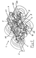
- Fig. 1 is a perspective view of a double-axle unit 1 of a commercial vehicle shown.
- the double-axle unit 1 is in the embodiment shown here arranged at the end of a vehicle frame, which among other things from longitudinal frame members 2, 3 and cross members, such as a cross member 20 and a final cross member 21 is composed.
- trailing arms 8, 9 for supporting and mounting the front and rear Longitudinal 4, 5 and wishbones 6, 7 arranged.
- the level below the Frame side members 2, 3 arranged front and rear wishbones 6, 7 are on the vehicle side in conjunction with the cross member 20 inside the vehicle the trailing arms 8, 9 articulated.
- the level below the Frame side members 2, 3 and the wishbone 6, 7 arranged front and rear trailing arms 4, 5 are in a lower region of trailing arms 8, 9 one end articulated.
- the other ends are the front and rear Trailing arms 4, 5 are articulated to the respective axle bodies 22, 23 (Fig. 3).
- the stabilizers can 10, 11 receiving trailing arms 8, 9 in principle for be provided and formed a single axis.
- FIG. 2 shows the double-axis unit 1 according to FIG. 1 in a top view.
- the frame of the commercial vehicle consists, among other things, of the frame longitudinal members 2, 3 and cross members, such as the cross member 20 and the Final cross member 21 together.
- the trailing arms 8, 9 both on the longitudinal frame members 2, 3 and attached to the cross member 20 via fastening means, not shown here.
- the stabilizers 10, 11 on the trailing arms brackets 8, 9 articulated are additionally for mounting the upper wishbones 6, 7 and those not shown here lower trailing arms.
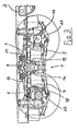
- FIG. 3 shows the double-axle unit 1 according to FIG. 1 in a side view.
- Trailing arm bracket 9 is a perspective view of the right trailing arm bracket 9 with the him articulated and fastened stabilizers 10, 11 and trailing arms 4, 5 shown.
- the one arranged on a vertical web 25 of the right frame side member 3 Trailing arm bracket 9 has a level that is just below the frame side member 3 arranged, for receiving the torison sections of the respective Front and rear recesses 12, 13 provided for stabilizers 10, 11 on.
- the respective depressions 12, 13 form in cooperation with it Area provided holding sleeves 14, 15 (Fig. 5) an annular, positive Recording and fastening for the end regions of the torsion sections 28, 29 of the respective stabilizers 10, 11.
- Fig. 5 is the right longitudinal link bracket attached to the right frame side member 3 9 shown in side view.
- the ring-shaped, form-fitting holder for the torsion sections 28, 29 of the respective stabilizers 10, 11 forming retaining sleeves 14, 15 and troughs 12, 13 are in the embodiment shown about fasteners not specified here, for example screw connections connected with each other. Thereby are between the of holding sleeves 14, 15 and hollows 12, 13 formed recordings and those held therein Stabilizers 10, 11 provided this damping elements 16, 17.
- These damping elements 16, 17 can be annular and, for example integrally connected to the torsion section of the stabilizers 10, 11 his.
- annular damping elements 16, 17 Half-shell plastic that can be completed to form a ring seat to form elements which are designed as components to be assembled separately.
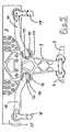
- FIG. 6 shows a right trailing arm bracket 9 according to FIG. 1 in plan view.
- the Trailing arm bracket 9 is, for example, via fastening means not shown here Screws or the like on the vertical web 25 of the right Frame side member 3 arranged.
- Below this frame side member 3 is each a front and a rear stabilizer 10, 11 from the trailing arm bracket 9 fixing added.
- the frame side member 3 shown here faces the outside of the vehicle horizontal webs oriented towards this - not provided with reference symbols on.
- the torsion sections 28, 29 run below the frame side member 3, the lever arm sections 26, 27 of the stabilizers 10, 11 advantageously in approximately in a surrounding area along the frame side member 3 and are supported.
Landscapes
- Engineering & Computer Science (AREA)
- Mechanical Engineering (AREA)
- Chemical & Material Sciences (AREA)
- Combustion & Propulsion (AREA)
- Transportation (AREA)
- Vehicle Body Suspensions (AREA)
Description
- Fig. 1
- in perspektivischer Darstellung ein Doppelachsaggregat eines Nutzfahrzeuges,
- Fig. 2
- ein Doppelachsaggregat gemäß Fig. 1 in Draufsicht,
- Fig. 3
- ein Doppelachsaggregat gemäß Fig. 1 in Seitenansicht,
- Fig. 4
- ausschnittsweise einen an einem Rahmenlängsträger eines Nutzfahrzeuges anordbaren Längslenkerbock mit hieran befestigten Stabilisatoren in perspektivischer Darstellung,
- Fig. 5
- einen Längslenkerbock gemäß Fig. 4 in Seitenansicht und
- Fig. 6
- einen Längslenkerbock gemäß Fig. 4 in Draufsicht.
Claims (6)
- Längslenkerbock an Rahmenlängsträgern (2,3) von Nutzfahrzeugen mit Mitteln zur Abstützung und Lagerung von Längslenkern (4,5) sowie wenigstens eines Stabilisators (10,11), dadurch gekennzeichnet, dass der Längslenkerbock (8,9) Mittel zur Abstützung und Lagerung von Dreieckslenkern und wenigstens eine Ausmuldung (12,13) zur bereichsweise umgreifenden Aufnahme des endseitigen Bereiches eines Torsionsabschnittes (28,29) des wenigstens einen, quer zur Ausmuldung (12,13) verlaufenden Stabilisators (10,11) aufweist, wobei zur Befestigung des jeweiligen Stabilisators (10,11) am Längslenkerbock (8,9) die Ausmuldung (12,13) mit einer den Stabilisator (10,11) bereichsweise umgreifenden Haltemuffe (14,15) zusammenwirkt.
- Längslenkerbock nach Anspruch 1, dadurch gekennzeichnet, dass der Stabilisator (10, 11) im Bereich seiner Fixierung umfangsmäßig von einem ringförmigen Dämpfungselement (16,17) umschlossen ist, welches von den zusammenwirkenden Ausmuldungen (12,13) des Längslenkerbockes (8,9) und der Haltemuffen (14,15) ringförmig umgriffen ist.
- Längslenkerbock nach einem der Ansprüche 1 und 2, dadurch gekennzeichnet, dass die die Stabilisatoren (10,11) am Längslenkerbock (8,9) lagernd aufnehmenden Ausmuldungen (12, 13) unterhalb der mit den Längslenkerböcken (8,9) verbundenen Rahmenlängsträger (2,3) angeordnet sind, so dass die quer zur Fahrtrichtung verlaufenden Torsionsabschnitte ( 28,29) der Stabilisatoren (10,11) unterhalb der Rahmenlängsträger (2,3) verlaufen.
- Längslenkerbock nach einem der Ansprüche 1 bis 3, dadurch gekennzeichnet, dass die in Fahrtrichtung verlaufenden Hebelarmabschnitte (26,27) der Stabilisatoren (10,11) eine lange Schenkellänge aufweisen, und dass die Hebelarmabschnitte (26,27) der Stabilisatoren (10,11) einen Randschatten des Fahrzeuges nicht überragen.
- Längslenkerbock nach einem der Ansprüche 1 bis 4, dadurch gekennzeichnet, dass der Längslenkerbock (8,9) wenigstens an Vertikalstegen (25) der Rahmenlängsträger (2,3) mittels Verschraubungen befestigt ist, und dass der Längslenkerbock (8,9 zusätzlich mit Rahmenquerträgem (20) fest verbunden ist.
- Längslenkerbock nach einem der Ansprüche 1 bis 5, dadurch gekennzeichnet, dass der Längslenkerbock (8,9) einem Doppelachsaggregat (1) eines Nutzfahrzeuges zugehörig ist.
Applications Claiming Priority (2)
| Application Number | Priority Date | Filing Date | Title |
|---|---|---|---|
| DE19961669A DE19961669A1 (de) | 1999-12-21 | 1999-12-21 | Längslenkerbock in Nutzfahrzeugen |
| DE19961669 | 1999-12-21 |
Publications (3)
| Publication Number | Publication Date |
|---|---|
| EP1110848A2 EP1110848A2 (de) | 2001-06-27 |
| EP1110848A3 EP1110848A3 (de) | 2002-11-20 |
| EP1110848B1 true EP1110848B1 (de) | 2004-09-01 |
Family
ID=7933571
Family Applications (1)
| Application Number | Title | Priority Date | Filing Date |
|---|---|---|---|
| EP00127042A Expired - Lifetime EP1110848B1 (de) | 1999-12-21 | 2000-12-09 | Längslenkerbock in Nutzfahrzeugen |
Country Status (2)
| Country | Link |
|---|---|
| EP (1) | EP1110848B1 (de) |
| DE (2) | DE19961669A1 (de) |
Cited By (5)
| Publication number | Priority date | Publication date | Assignee | Title |
|---|---|---|---|---|
| EP2159135A1 (de) | 2008-08-29 | 2010-03-03 | MAN Nutzfahrzeuge AG | Nutzfahrzeugrahmen mit modularem Multifunktionslagerblock |
| DE102010054220A1 (de) | 2010-12-11 | 2011-08-25 | Daimler AG, 70327 | Lagerbockanordnung |
| EP2607211A2 (de) | 2011-12-22 | 2013-06-26 | MAN Truck & Bus AG | Nutzfahrzeug mit einem modularen Fahrgestellrahmen, dessen Längsträger durch Querträger verbunden sind |
| RU2712399C2 (ru) * | 2015-08-01 | 2020-01-28 | Ивеко Магирус Аг | Пневматическая подвеска оси для задней оси транспортного средства |
| AU2016296919B2 (en) * | 2015-07-23 | 2020-02-27 | Iveco Magirus Ag | Pneumatic axle suspension for a rear axle of a vehicle |
Families Citing this family (6)
| Publication number | Priority date | Publication date | Assignee | Title |
|---|---|---|---|---|
| WO2012060745A1 (en) * | 2010-11-05 | 2012-05-10 | Volvo Lastavagnar Ab | Suspension arrangement for a vehicle axle and vehicle comprising a suspension arrangement |
| DE102012011416A1 (de) * | 2012-06-08 | 2013-12-12 | Man Truck & Bus Ag | Tragbock für eine einen Querträger umfassende Tragkonstruktion für ein Kraftfahrzeug |
| SE541216C2 (en) * | 2017-09-06 | 2019-05-07 | Scania Cv Ab | A vehicle suspension arrangement for at least one wheel axle |
| US11207934B2 (en) * | 2018-11-16 | 2021-12-28 | Saf-Holland, Inc. | Vehicle suspension assembly |
| IT201900002405A1 (it) * | 2019-02-19 | 2020-08-19 | Iveco Spa | Sistema di sospensione per veicolo pesante |
| DE102019219095A1 (de) | 2019-12-06 | 2021-06-10 | Zf Friedrichshafen Ag | Doppelachsaggregat für ein nicht-gleisgebundenes Nutzfahrzeug |
Family Cites Families (13)
| Publication number | Priority date | Publication date | Assignee | Title |
|---|---|---|---|---|
| DE1256598B (de) * | 1966-06-29 | 1967-12-21 | Salzgitter Maschinen Ag | Rotaryspuelbohrgeraet |
| FR2063097B1 (de) * | 1969-09-09 | 1973-03-16 | Fruehauf France | |
| JPS5843443Y2 (ja) * | 1977-08-29 | 1983-10-01 | トヨタ自動車株式会社 | 自動車の前輪支持装置 |
| FR2480683A1 (fr) * | 1980-04-21 | 1981-10-23 | Peugeot | Dispositif de maintien transversal de la barre antidevers dans une suspension de vehicule automobile |
| JPS58170607A (ja) * | 1982-03-31 | 1983-10-07 | Nissan Motor Co Ltd | 懸架装置の支持メンバ |
| DE3607748A1 (de) * | 1986-03-08 | 1987-09-17 | Opel Adam Ag | Kraftfahrzeug |
| DD250096A1 (de) * | 1986-06-23 | 1987-09-30 | Sachsenring Automobilwerke | Hilfsrahmen fuer frontgetriebenes kleinkraftfahrzeug |
| DE4129538C2 (de) * | 1991-09-05 | 1993-11-18 | Porsche Ag | Fahrschemel für ein Kraftfahrzeug |
| JP3432578B2 (ja) * | 1994-03-09 | 2003-08-04 | 本田技研工業株式会社 | 自動車のサブフレーム |
| US5862877A (en) * | 1994-12-20 | 1999-01-26 | Cosma International Inc. | Cradle assembly |
| SE9503271L (sv) * | 1995-09-21 | 1997-03-22 | Scania Cv Ab | Chassidel |
| US5879026A (en) * | 1995-12-19 | 1999-03-09 | Chrysler Corporation | Vehicle suspension and steering cradle |
| DE59708237D1 (de) * | 1996-06-21 | 2002-10-24 | Volkswagen Ag | Hilfsrahmen für ein Kraftfahrzeug |
-
1999
- 1999-12-21 DE DE19961669A patent/DE19961669A1/de not_active Withdrawn
-
2000
- 2000-12-09 EP EP00127042A patent/EP1110848B1/de not_active Expired - Lifetime
- 2000-12-09 DE DE50007611T patent/DE50007611D1/de not_active Expired - Lifetime
Cited By (7)
| Publication number | Priority date | Publication date | Assignee | Title |
|---|---|---|---|---|
| EP2159135A1 (de) | 2008-08-29 | 2010-03-03 | MAN Nutzfahrzeuge AG | Nutzfahrzeugrahmen mit modularem Multifunktionslagerblock |
| DE102008045008A1 (de) | 2008-08-29 | 2010-03-04 | Man Nutzfahrzeuge Aktiengesellschaft | Modularer Multifunktionslagerbock |
| DE102010054220A1 (de) | 2010-12-11 | 2011-08-25 | Daimler AG, 70327 | Lagerbockanordnung |
| EP2607211A2 (de) | 2011-12-22 | 2013-06-26 | MAN Truck & Bus AG | Nutzfahrzeug mit einem modularen Fahrgestellrahmen, dessen Längsträger durch Querträger verbunden sind |
| DE102011122460A1 (de) | 2011-12-22 | 2013-06-27 | Man Truck & Bus Ag | Nutzfahrzeug mit einem modularen Fahrgestellrahmen, dessen Längsträger durch Querträger verbunden sind |
| AU2016296919B2 (en) * | 2015-07-23 | 2020-02-27 | Iveco Magirus Ag | Pneumatic axle suspension for a rear axle of a vehicle |
| RU2712399C2 (ru) * | 2015-08-01 | 2020-01-28 | Ивеко Магирус Аг | Пневматическая подвеска оси для задней оси транспортного средства |
Also Published As
| Publication number | Publication date |
|---|---|
| DE19961669A1 (de) | 2001-06-28 |
| EP1110848A3 (de) | 2002-11-20 |
| DE50007611D1 (de) | 2004-10-07 |
| EP1110848A2 (de) | 2001-06-27 |
Similar Documents
| Publication | Publication Date | Title |
|---|---|---|
| DE10219275B4 (de) | Fahrgestell für ein Nutzfahrzeug | |
| EP0656270B1 (de) | Radaufhängung | |
| DE19957628B4 (de) | Achsaufhängung für Starrachsen von Fahrzeugen | |
| DE102014205632B4 (de) | Einzelradaufhängung sowie Hinterachse mit Einzelradaufhängungen für ein Fahrzeug und entsprechend ausgestattetes Fahrzeug | |
| DE102013210338A1 (de) | Mehrlenkerhinterachse für ein Fahrzeug | |
| WO2003008212A1 (de) | Hinterachse eines personenkraftwagens mit fünf einzelnen lenkern | |
| DE102017217190A1 (de) | Mehrlenkerhinterachse und Kraftfahrzeug | |
| EP1900554A1 (de) | Einzelradaufhängung vom Doppelquerlenker-Typ | |
| EP1110848B1 (de) | Längslenkerbock in Nutzfahrzeugen | |
| EP0806310B1 (de) | Einzelradaufhängung für ein luftgefedertes, lenkbares Rad eines Omnibusses oder Lastkraftwagens | |
| EP1346854B1 (de) | Radaufhängung für ein Kraftfahrzeug | |
| EP1592570B1 (de) | Radaufhängung für kraftfahrzeuge | |
| DE4126128C2 (de) | Anordnung zum Anbringen einer Aufhängungseinheit an einer Fahrzeugkarosserie | |
| DE102014205635A1 (de) | Einzelradaufhängung sowie Hinterachse mit Einzelradaufhängungen für ein Fahrzeug und entsprechend ausgestattetes Fahrzeug | |
| DE60102492T2 (de) | Vorderradaufhängung mit transversaler Blattfeder | |
| DE1924175B2 (de) | Hinterradaufhaengung fuer kraftfahrzeuge | |
| DE10157712A1 (de) | Blattgefederte Hinterachsaufhängung für Fahrzeuge | |
| EP0940320B1 (de) | Fahrgestell eines schweren Nutzfahrzeuges | |
| WO2008061488A1 (de) | Stabilisatoreinrichtung mit radführungslenker | |
| DE202014101432U1 (de) | Einzelradaufhängung sowie Hinterachse mit Einzelradaufhängungen für ein Fahrzeug und entsprechend ausgestattetes Fahrzeug | |
| DE102019208444A1 (de) | Radträger für ein Fahrzeug | |
| DE4008465A1 (de) | Vorspannbares lager | |
| EP0464415B1 (de) | Kurbelachse für Kraftfahrzeuge und Anhänger | |
| DE102017211277A1 (de) | Radaufhängung für ein Kraftfahrzeug | |
| DE69325134T2 (de) | Hinterradaufhängung für Kraftfahrzeug mit unabhängigen Rädern |
Legal Events
| Date | Code | Title | Description |
|---|---|---|---|
| PUAI | Public reference made under article 153(3) epc to a published international application that has entered the european phase |
Free format text: ORIGINAL CODE: 0009012 |
|
| AK | Designated contracting states |
Kind code of ref document: A2 Designated state(s): AT BE CH CY DE DK ES FI FR GB GR IE IT LI LU MC NL PT SE TR |
|
| AX | Request for extension of the european patent |
Free format text: AL;LT;LV;MK;RO;SI |
|
| PUAL | Search report despatched |
Free format text: ORIGINAL CODE: 0009013 |
|
| AK | Designated contracting states |
Kind code of ref document: A3 Designated state(s): AT BE CH CY DE DK ES FI FR GB GR IE IT LI LU MC NL PT SE TR |
|
| AX | Request for extension of the european patent |
Free format text: AL;LT;LV;MK;RO;SI |
|
| 17P | Request for examination filed |
Effective date: 20021218 |
|
| 17Q | First examination report despatched |
Effective date: 20030325 |
|
| AKX | Designation fees paid |
Designated state(s): DE FR IT NL SE |
|
| GRAP | Despatch of communication of intention to grant a patent |
Free format text: ORIGINAL CODE: EPIDOSNIGR1 |
|
| GRAS | Grant fee paid |
Free format text: ORIGINAL CODE: EPIDOSNIGR3 |
|
| GRAA | (expected) grant |
Free format text: ORIGINAL CODE: 0009210 |
|
| AK | Designated contracting states |
Kind code of ref document: B1 Designated state(s): DE FR IT NL SE |
|
| REG | Reference to a national code |
Ref country code: IE Ref legal event code: FG4D Free format text: GERMAN |
|
| REF | Corresponds to: |
Ref document number: 50007611 Country of ref document: DE Date of ref document: 20041007 Kind code of ref document: P |
|
| REG | Reference to a national code |
Ref country code: SE Ref legal event code: TRGR |
|
| REG | Reference to a national code |
Ref country code: IE Ref legal event code: FD4D |
|
| PLBE | No opposition filed within time limit |
Free format text: ORIGINAL CODE: 0009261 |
|
| STAA | Information on the status of an ep patent application or granted ep patent |
Free format text: STATUS: NO OPPOSITION FILED WITHIN TIME LIMIT |
|
| ET | Fr: translation filed | ||
| 26N | No opposition filed |
Effective date: 20050602 |
|
| REG | Reference to a national code |
Ref country code: NL Ref legal event code: TD Effective date: 20110420 |
|
| REG | Reference to a national code |
Ref country code: FR Ref legal event code: CD |
|
| REG | Reference to a national code |
Ref country code: DE Ref legal event code: R081 Ref document number: 50007611 Country of ref document: DE Owner name: MAN TRUCK & BUS AG, DE Free format text: FORMER OWNER: MAN NUTZFAHRZEUGE AG, 80995 MUENCHEN, DE Effective date: 20110518 |
|
| REG | Reference to a national code |
Ref country code: FR Ref legal event code: PLFP Year of fee payment: 16 |
|
| REG | Reference to a national code |
Ref country code: FR Ref legal event code: PLFP Year of fee payment: 17 |
|
| REG | Reference to a national code |
Ref country code: FR Ref legal event code: PLFP Year of fee payment: 18 |
|
| REG | Reference to a national code |
Ref country code: DE Ref legal event code: R081 Ref document number: 50007611 Country of ref document: DE Owner name: MAN TRUCK & BUS SE, DE Free format text: FORMER OWNER: MAN TRUCK & BUS AG, 80995 MUENCHEN, DE |
|
| PGFP | Annual fee paid to national office [announced via postgrant information from national office to epo] |
Ref country code: SE Payment date: 20191227 Year of fee payment: 20 Ref country code: NL Payment date: 20191223 Year of fee payment: 20 |
|
| PGFP | Annual fee paid to national office [announced via postgrant information from national office to epo] |
Ref country code: FR Payment date: 20191230 Year of fee payment: 20 |
|
| PGFP | Annual fee paid to national office [announced via postgrant information from national office to epo] |
Ref country code: IT Payment date: 20191223 Year of fee payment: 20 Ref country code: DE Payment date: 20200227 Year of fee payment: 20 |
|
| REG | Reference to a national code |
Ref country code: NL Ref legal event code: MK Effective date: 20201208 Ref country code: DE Ref legal event code: R071 Ref document number: 50007611 Country of ref document: DE |
|
| REG | Reference to a national code |
Ref country code: SE Ref legal event code: EUG |