EP1108620A2 - A grommet for a door - Google Patents
A grommet for a door Download PDFInfo
- Publication number
- EP1108620A2 EP1108620A2 EP00127459A EP00127459A EP1108620A2 EP 1108620 A2 EP1108620 A2 EP 1108620A2 EP 00127459 A EP00127459 A EP 00127459A EP 00127459 A EP00127459 A EP 00127459A EP 1108620 A2 EP1108620 A2 EP 1108620A2
- Authority
- EP
- European Patent Office
- Prior art keywords
- grommet
- door
- wire harness
- side portion
- door body
- Prior art date
- Legal status (The legal status is an assumption and is not a legal conclusion. Google has not performed a legal analysis and makes no representation as to the accuracy of the status listed.)
- Granted
Links
Images


Classifications
-
- B—PERFORMING OPERATIONS; TRANSPORTING
- B60—VEHICLES IN GENERAL
- B60R—VEHICLES, VEHICLE FITTINGS, OR VEHICLE PARTS, NOT OTHERWISE PROVIDED FOR
- B60R16/00—Electric or fluid circuits specially adapted for vehicles and not otherwise provided for; Arrangement of elements of electric or fluid circuits specially adapted for vehicles and not otherwise provided for
- B60R16/02—Electric or fluid circuits specially adapted for vehicles and not otherwise provided for; Arrangement of elements of electric or fluid circuits specially adapted for vehicles and not otherwise provided for electric constitutive elements
- B60R16/0207—Wire harnesses
- B60R16/0215—Protecting, fastening and routing means therefor
- B60R16/0222—Grommets
Definitions
- This invention relates to a grommet for a door of an automobile.
- this invention relates to a grommet that improves waterproofness at a position where a wire harness is mounted to extend from an automobile body to a door body.
- a wire harness mounted to extend from the automobile body to the door body sometimes avoids the interior of the door body and passes through a passenger compartment side.
- the wire harness mounted as described above passes through an opening provided in an inner plate portion, which is on a passenger compartment side of the door body, to provide a required connection.
- a trim cover is mounted to cover an entire surface at the passenger compartment side of the inner plate portion of the door body so that the wire harness is prevented from being exposed to the exterior.
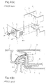
- Figs. 4(A) and 4(B) schematically show a mounting structure of a wire harness extending from the automobile body 1 to the passenger compartment side R of the door body, which is proposed by the Japanese Laid-Open Publication Nos. 7-179156 and 8-40155.
- an L-shaped recess 2c is formed to extend from a side plate portion 2a, which is a front side of the door body 2 and on which a hinge is attached, to an inner plate portion 2b at the passenger compartment side.
- an attachment member 3 that covers the recess 2c is mounted by using bolts 8.
- the attachment member 3 includes an L-shaped plate 4, such as an iron plate or a resin plate, which has a through-hole 4a, and a watertight packing 5 attached on the interior surface (facing the door body) of the L-shaped plate 4. Further, a grommet 6, in which a wire harness W/H is inserted, is mounted at the through-hole 4a.
- the wire harness W/H extending from the door side of the grommet 6 passes through a space K formed by the attachment member 3 and the recess 2c in the door body 2, and extends toward the passenger compartment side R of the inner plate portion 2b of the door body 2, so as not to pass through the interior 2g of the door body 2, where water is likely to intrude.
- a weather strip 7 is provided on the side plate portion 2a of the door body 2 so as to pass over the attachment member 3. Further, after the completion of mounting the wire harness, a trim cover 9, which covers the inner plate portion 2b, is attached to the passenger compartment side R of the inner plate portion 2b of the door body 2.
- the wire harness W/H provided as describe above is formed by bundling a predetermined number of wires, it has a constant (predetermined) cross section. Accordingly, in order to insert the wire harness W/H into the space K formed by the recess 2c of the door body 2 and the attachment member 3, the cross section of the space K should be made larger than the cross section of the wire harness W/H.
- two avenues can be considered, i.e., increasing the depth of the recess 2c, or increasing the vertical width of the recess 2c.
- the door body 2 is formed by press molding, machining to increase the depth of the recess is difficult and requires high cost.
- the vertical width T of the attachment member 3 is set between 120 and 150 mm.
- the weather strip 7 attached on the side plate portion 2a cannot be directly attached to the door body 2 at the position where it crosses over the attachment member 3, the weather strip 7 might lose touch with the wide attachment member 3, and it becomes difficult to ensure waterproofness.
- the attachment member 3 itself is provided with the L-shaped (iron) plate 4, the watertight packing 5 and the grommet 6, the number of parts is large, and thus, the cost becomes high. Further, since the attachment member 3 is mounted on the door body 2 by fastening with the bolts 8, the mounting operation takes a long time. Furthermore, because the path of the wire harness W/H to be mounted requires that it be bent about 90 degrees at two positions, i.e., at the side plate portion 2a and at the inner plate portion 2b of the door body 2, the mounting operation becomes difficult and cannot be performed efficiently. In addition, the wire harness W/H itself, when bent to such an extent, is subject to increased stress.
- Japanese Laid-Open Publication No. 9-76837 proposed a mounting structure of a wire harness (note Fig. 5).
- an opening 2d' is continuously notched from a side plate portion 2a' to an inner plate portion 2b' in the passenger compartment side of the door body 2', and a recessed portion 2e' is provided at the periphery of the opening 2d' in the side plate portion 2a'.
- a grommet 6' which is an attachment member of the wire harness, is integrally formed with a weather strip 7' and has an L-shape.
- a bellows portion 6b' extends from a front surface 6a' and the wire harness W/H passing through the bellows portion 6b' extends toward the side surface (passenger compartment side portion) 6c'.
- the weather strip 7' and the grommet 6' are formed unitarily in one piece as a single unit, waterproofness is ensured. Further, due to the engaging structure between the grommet 6' and the door body 2', the efficiency of mounting of the grommet 6' to the door body 2' improves. However, due to the unitary structure of the weather strip 7' and the grommet 6', a molding die becomes large and complicated, and the manufacturing costs for the die become very expensive. To engage with the grommet 6', the recessed portion 2e' is provided, which results in the shape of the cross section of the door body 2'being complicated. As a result. the cost of machining of the door body 2' becomes higher.
- wire harness W/H is exposed to the exterior from the bellows portion 6b' to a passenger compartment side portion 6c', water that travels along a glass and intrudes into the interior of the door body 2' may splash on the wire harness W/H.
- the present invention is provided in view of the above-described problems, and an objective of the present invention is to reduce the vertical width of the grommet mounted on the door body by diagonally mounting the wire harness from the front surface side to the passenger compartment side of the door body, so as to improve appearance when viewed from the outside and to improve waterproofness.
- the present invention provides a grommet for a door in which a wire harness to be mounted to extend from an automobile body to a door body is to be inserted.
- the grommet is configured to engage with an opening continuously provided in a front surface and a side surface of the door body. The front surface and the side surface connect with each other at a predetermined angle.
- the grommet includes a bellows portion into which the wire harness is to be inserted, a door mounting base portion, and an automobile mounting base portion configured to engage with the automobile body.
- the automobile mounting base portion extends past an end of the bellows portion.
- the door mounting base portion includes a front side portion from which the bellows portion extends and that covers the opening in the front surface of the door body, a passenger compartment side portion that connects with the front side portion at the predetermined angle and covers the opening in the side surface of the door body and having a wire inserting through-hole, and a wire harness protecting portion that extends diagonally between the front side portion and the passenger compartment side portion so as to connect the bellows portion and the wire inserting through-hole.
- the wire harness is insertable into the wire harness protecting portion.
- the front side portion of the door mounting base portion may include a recessed portion on which a weather strip is mountable.
- the vertical width of the door mounting base portion of the grommet mounted to the door body can be short, and as a result, an area of the grommet exposed to the exterior can be reduced and the appearance can be improved. Further, due to the reducing of the vertical width, an area of the grommet over which the weather strip is mounted becomes short. Thus, the more portion of the weather strip can be mounted on the door body, and thus, the weather strip can be securely mounted, and can be prevented from separating from the door body, and waterproofness can be ensured.
- the grommet described above is provided with the door mounting base portion, the bellows portion and the automobile body mounting base portion unitarily formed in one piece as a single unit, a mounting operation can be performed easily. Further, since the wire harness W/H is covered by the wire harness protecting portion of the door mounting base portion even at the position from the front surface to the passenger compartment surface, the possibility that water will splash on the wire harness is reduced. Further, since the wire harness is diagonally mounted from the front surface to the passenger compartment surface to pass through the wire harness through-hole, the wire harness is bent at obtuse angles, and thus, an operation to insert the wire harness into the grommet can be performed easily.
- an engaging recessed portion to engage with the door body is provided in an entire periphery of the front side portion and the passenger compartment side portion, and a lip projects from an end of the engaging recessed portion about the entire periphery of the front side portion and the passenger compartment side portion.
- the grommet which engages with the opening (notch) of the door body, can be securely fixed by the engaging recessed portion, and waterproofness at the engaging position can be ensured by the lip.
- a drain hole is provided in the lip at the position of the recessed portion for the weather strip so that the drain hole extends between the engaging recessed portion and a bottom of the recessed portion for the weather strip. Due to the drain hole provided as described above, even if water passes through a gap between the weather strip and the grommet (or the door body), the water passes through the drain hole and is discharged into the interior of the door body via the engaging recessed portion. Thus, waterproofness can be ensured.
- a pair of drain holes are respectively provided in upper and lower lips of the door mounting base portion so that the door mounting base portion has a vertically symmetric structure. Due to the symmetric structure, the grommet for a door can be used with both right and left doors, and thus, parts can be efficiently used.
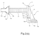
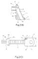
- Fig. 1 and Figs. 2(A)-2(C) illustrate a grommet 10 for a door into which a wire harness to be mounted to extend between an automobile body and a door body 20 is inserted.
- the grommet 10 is unitarily formed to include a door mounting base portion 11 to be mounted on the door body 20, an automobile body mounting base portion 12 to be mounted on an automobile body, and a bellows portion 13 that extends between the door mounting base portion 11 and the automobile body mounting base portion 12.
- the above-described parts could be separately formed and interconnected in any suitable manner to form the grommet of the present invention.
- the door grommet 10 is made of any suitable material, such as a rubber or elastomer, which has flexibility and elasticity.
- the door body 20 on which the door grommet 10 is mounted has an L-shaped opening 20d continuously notched from the side plate portion 20a at the front side to the inner plate portion 20b at the passenger compartment side.
- Mounting holes 20f for mounting a weather strip 27 are provided in the side plate portion 20a with a small pitch.
- the door mounting base portion 11 of the door grommet 10 is formed as a block so as to engage with the opening 20d of the door body 20.
- the vertical width T' (Fig. 2(C)) is shorter than the width of the conventional grommet, and is set to be, for example, about 50 mm in the present embodiment.
- a front side portion 14 is positioned to cover the opening 20d in the side plate portion 20a, which is positioned at a front surface side
- a passenger compartment side portion 15 is positioned to cover the opening 20d in the inner plate portion 20b, which is positioned at a passenger compartment surface side.
- the front side portion 14 and the passenger compartment side portion 15 are connected at a right angle.
- a recessed portion 14c for mounting the weather strip 27 is provided on the surface of the front side portion near a connection side 14b.
- a wire harness through-hole 15b is provided near an end portion 15a of the passenger compartment side portion 15.
- the front side portion 14 and the passenger compartment side portion 15 are not required to connect at the right angle, rather the angle can be changed (adjusted) according to an angle between the side plate portion 20a and the inner plate portion 20b of the door body 20.
- the door grommet 10 has a wire harness protecting portion 16, which extends between the front side portion 14 and the passenger compartment side portion 15.
- the wire harness protecting portion 16 has an inserting portion 16a that diagonally extends between the hollow portion 13a, which protrudes from the front side portion 14 at the position aligning with the bellows portion 13, and the wire harness through-hole 15b in the passenger compartment side portion 15.
- the cross section of the inserting portion 16a has a generally circular shape and has a diameter larger than that of the wire harness inserted therein.
- the door mounting base portion 11 of the door grommet 10 since the door mounting base portion 11 of the door grommet 10 has the inserting portion 16a with a predetermined cross sectional size and that diagonally extends from the front side portion 14 to the passenger compartment side portion 15, it has a large depth. However, since the door mounting base portion 11 is mounted to the opening 20d, which does not have a bottom surface, the grommet 10 can be mounted without interference. Further, since the door grommet 10 has a large depth so as to provide a cross section sufficient to insert the wire harness, the vertical width T' can be minimized, as described above.
- the door grommet 10 has an engaging recessed portion 17 having a width corresponding to the plate thickness of the door body 20, about the entire periphery of the front side portion 14 and the passenger compartment side portion 15. Further, a lip 18 projects from an edge of the engaging recessed portion 17 provided in the entire periphery of the front side portion 14 and the passenger compartment side portion 15. Further, as shown in Figs. 1, 2(A) and 2(C), the lip 18 has drain holes 19 opened at the position of the recessed portion 14c for mounting a weather strip. The drain holes 19 pierce the lip 18 from the front side portion 14 side to the engaging recessed portion 17 side. In the present embodiment, the drain holes 19 are provided at the position of the recessed portion 14c in both of the upper and lower lips 18, so that the door grommet 10 has a vertically symmetric structure, which can be used with both the right and left door bodies.
- the length of the bellows portion 13 extending from the door mounting base portion 11 is determined according to the spacing between the door body 20 and the automobile body, when the door is opened. Further, the automobile body mounting base portion 12, which extends from the extended end portion 13b of the bellows portion 13, has a large-diameter portion 12a, a tapered portion 12b and a small-diameter portion 12c continuously formed from the bellows portion 13 side. A recessed portion 12d for engaging with the automobile body is provided between the large-diameter portion 12a and the tapered portion 12b.
- the door grommet 10 When the wire harness W/H is mounted to extend from the automobile body to the door body 20 by using the above-described door grommet 10, first, during the manufacturing process of the wire harness W/H, the door grommet 10 is mounted on the wire harness W/H at the position for mounting on the door body 20. At this time, since the inserting portion 16a diagonally extends between the front side portion 14 and the passenger compartment side portion 15, an angle at a connection point of the front side portion 14 and the inserting portion 16a, and an angle at a connection point of the passenger compartment side portion 15 and the inserting portion 16a, become obtuse-angles, which are more than 90 degrees, and thus, the inserting operation for the wire harness becomes easy.
- the door grommet 10 in which the wire harness W/H is inserted is mounted on the door body 20, by engaging with the opening 20d provided in the door body 20, as shown in Fig. 1. Since the opening 20d is provided by simply notching the side plate portion 20a and the inner plate portion 20b continuously, and no special machining is performed, there is no special (or particular) cost to form the opening 20d. Further, after the engagement, as shown in Figs. 3(A) and 3(B), the lip 18 tightly contacts the side plate portion 20a and the inner plate portion 20b of the door body 20 so as to ensure an efficient seal at the engaging position. Further, since the front side portion 14 and the passenger compartment side portion 15 connect with each other at a right angle, they are mutually prevented from separating from the door body 20 in the engaged condition, and thus, the engaged condition can be securely maintained.
- the weather strip 27 is mounted on the side plate portion 20a of the door body 20 and on the recessed portion 14c of the door grommet 10. At this time, since the vertical width of the door grommet 10 is short, the length of the weather strip 27 that crosses over the door grommet 10 becomes shorter than the conventional structure. Further, since the mounting holes 20f are provided with a short pitch, the weather strip 27 can be securely mounted, and thus, separation of the weather strip 27 from the upper and lower sides of the door grommet 10 can be reduced.
- a trim cover 25 (Fig. 3(A)) is provided to cover the entire surface of the passenger compartment side of the inner plate portion 20b of the door body 20, and thus the mounted wire harness W/H is prevented from being exposed to the exterior.
- the automobile body mounting base portion 12 of the door grommet 10 engages with an engaging hole (not shown) in the automobile body to perform a required connection of the mounted wire harness W/H.
- the wire harness W/H is naturally mounted in the passenger compartment side R of the door body 20 without being exposed to the exterior at the position between the automobile body and the door body.
- the size, the shape, etc., of the grommet of the present invention can be modified according to a variety of shapes of door bodies and automobile bodies, etc.
- the grommet for a door of the present invention since the vertical width is minimized, the area exposed to the exterior is reduced when the grommet is mounted on the door, and thus, the deterioration of the appearance can be prevented. Further, the mounting efficiency of the weather strip on the door body can be improved, and the waterproofness can also be improved. In addition, since the door grommet itself is provided unitarily and in one piece as a single unit without combining with other parts, the manufacturing cost of the grommet can be reduced. In addition, since the mounting of the grommet to the door body can be performed without using bolts and so on, the mounting operation becomes efficient.
- a grommet for a door is provided with a door mounting base portion, an automobile mounting base portion and a bellows portion.
- the door mounting portion includes a front side portion, from which the bellows portion extends, a passenger compartment side portion, which includes a wire harness through-hole, and a wire harness protecting portion extending diagonally between the front side portion and the passenger compartment side portion.
- the vertical width of the grommet is made short to reduce an area of the grommet that is exposed to the exterior and that is overlapped with the weather strip. Due to the structure described above, the grommet can be efficiently mounted to the door body, and waterproofness can be ensured.
Abstract
Description
- This invention relates to a grommet for a door of an automobile. In particular, this invention relates to a grommet that improves waterproofness at a position where a wire harness is mounted to extend from an automobile body to a door body.
- Since water travels along a glass that moves up and down, and intrudes into the interior of right and left door bodies of an automobile, a wire harness mounted to extend from the automobile body to the door body sometimes avoids the interior of the door body and passes through a passenger compartment side. The wire harness mounted as described above, passes through an opening provided in an inner plate portion, which is on a passenger compartment side of the door body, to provide a required connection. Further, a trim cover is mounted to cover an entire surface at the passenger compartment side of the inner plate portion of the door body so that the wire harness is prevented from being exposed to the exterior.
- Figs. 4(A) and 4(B) schematically show a mounting structure of a wire harness extending from the
automobile body 1 to the passenger compartment side R of the door body, which is proposed by the Japanese Laid-Open Publication Nos. 7-179156 and 8-40155. In the mounting structure, an L-shaped recess 2c is formed to extend from aside plate portion 2a, which is a front side of thedoor body 2 and on which a hinge is attached, to aninner plate portion 2b at the passenger compartment side. Further, anattachment member 3 that covers therecess 2c is mounted by usingbolts 8. - The
attachment member 3 includes an L-shaped plate 4, such as an iron plate or a resin plate, which has a through-hole 4a, and a watertight packing 5 attached on the interior surface (facing the door body) of the L-shaped plate 4. Further, agrommet 6, in which a wire harness W/H is inserted, is mounted at the through-hole 4a. The wire harness W/H extending from the door side of thegrommet 6 passes through a space K formed by theattachment member 3 and therecess 2c in thedoor body 2, and extends toward the passenger compartment side R of theinner plate portion 2b of thedoor body 2, so as not to pass through the interior 2g of thedoor body 2, where water is likely to intrude. Further, a weather strip 7 is provided on theside plate portion 2a of thedoor body 2 so as to pass over theattachment member 3. Further, after the completion of mounting the wire harness, a trim cover 9, which covers theinner plate portion 2b, is attached to the passenger compartment side R of theinner plate portion 2b of thedoor body 2. - Since the wire harness W/H provided as describe above is formed by bundling a predetermined number of wires, it has a constant (predetermined) cross section. Accordingly, in order to insert the wire harness W/H into the space K formed by the
recess 2c of thedoor body 2 and theattachment member 3, the cross section of the space K should be made larger than the cross section of the wire harness W/H. To make the cross section of the space K larger, two avenues can be considered, i.e., increasing the depth of therecess 2c, or increasing the vertical width of therecess 2c. However, since thedoor body 2 is formed by press molding, machining to increase the depth of the recess is difficult and requires high cost. Thus, it is more realistic to increase the vertical width of the recess. Accordingly, the width in a vertical direction of therecess 2c is increased so that the wire harness W/H can be inserted therein. - When the vertical width of the
recess 2c is increased, it is necessary to increase the vertical width of theattachment member 3, which covers therecess 2c. Generally, the vertical width T of theattachment member 3 is set between 120 and 150 mm. As a result, since an area in which theattachment member 3 is exposed to the exterior becomes large at theside plate portion 2a of thedoor body 2, the appearance becomes worse. Further, since the weather strip 7 attached on theside plate portion 2a cannot be directly attached to thedoor body 2 at the position where it crosses over theattachment member 3, the weather strip 7 might lose touch with thewide attachment member 3, and it becomes difficult to ensure waterproofness. - Further, since the
attachment member 3 itself is provided with the L-shaped (iron)plate 4, the watertight packing 5 and thegrommet 6, the number of parts is large, and thus, the cost becomes high. Further, since theattachment member 3 is mounted on thedoor body 2 by fastening with thebolts 8, the mounting operation takes a long time. Furthermore, because the path of the wire harness W/H to be mounted requires that it be bent about 90 degrees at two positions, i.e., at theside plate portion 2a and at theinner plate portion 2b of thedoor body 2, the mounting operation becomes difficult and cannot be performed efficiently. In addition, the wire harness W/H itself, when bent to such an extent, is subject to increased stress. Further, if a gap occurs at the contact point S between the watertight packing 5 and theside plate portion 2a, due to the vibration of the automobile body or age deterioration, etc., water intrudes and splashes on the wire harness W/H, a short or the like might occur in the worst case. - To solve the problem described above, Japanese Laid-Open Publication No. 9-76837 proposed a mounting structure of a wire harness (note Fig. 5). In the mounting structure, an opening 2d' is continuously notched from a
side plate portion 2a' to aninner plate portion 2b' in the passenger compartment side of the door body 2', and arecessed portion 2e' is provided at the periphery of the opening 2d' in theside plate portion 2a'. Further, a grommet 6', which is an attachment member of the wire harness, is integrally formed with a weather strip 7' and has an L-shape. Abellows portion 6b' extends from afront surface 6a' and the wire harness W/H passing through thebellows portion 6b' extends toward the side surface (passenger compartment side portion) 6c'. - In the attachment structure described above, since the weather strip 7' and the grommet 6' are formed unitarily in one piece as a single unit, waterproofness is ensured. Further, due to the engaging structure between the grommet 6' and the door body 2', the efficiency of mounting of the grommet 6' to the door body 2' improves. However, due to the unitary structure of the weather strip 7' and the grommet 6', a molding die becomes large and complicated, and the manufacturing costs for the die become very expensive. To engage with the grommet 6', the
recessed portion 2e' is provided, which results in the shape of the cross section of the door body 2'being complicated. As a result. the cost of machining of the door body 2' becomes higher. Further, because the wire harness W/H is exposed to the exterior from thebellows portion 6b' to a passengercompartment side portion 6c', water that travels along a glass and intrudes into the interior of the door body 2' may splash on the wire harness W/H. - Accordingly, the present invention is provided in view of the above-described problems, and an objective of the present invention is to reduce the vertical width of the grommet mounted on the door body by diagonally mounting the wire harness from the front surface side to the passenger compartment side of the door body, so as to improve appearance when viewed from the outside and to improve waterproofness.
- To achieve the above and/or other goals, the present invention provides a grommet for a door in which a wire harness to be mounted to extend from an automobile body to a door body is to be inserted. The grommet is configured to engage with an opening continuously provided in a front surface and a side surface of the door body. The front surface and the side surface connect with each other at a predetermined angle. The grommet includes a bellows portion into which the wire harness is to be inserted, a door mounting base portion, and an automobile mounting base portion configured to engage with the automobile body. The automobile mounting base portion extends past an end of the bellows portion. The door mounting base portion includes a front side portion from which the bellows portion extends and that covers the opening in the front surface of the door body, a passenger compartment side portion that connects with the front side portion at the predetermined angle and covers the opening in the side surface of the door body and having a wire inserting through-hole, and a wire harness protecting portion that extends diagonally between the front side portion and the passenger compartment side portion so as to connect the bellows portion and the wire inserting through-hole. The wire harness is insertable into the wire harness protecting portion. The front side portion of the door mounting base portion may include a recessed portion on which a weather strip is mountable.
- When the above-described grommet is mounted in an opening of the door body, which has little restriction to the depth thereof, and the wire harness is diagonally mounted, an area corresponding to the cross section of the wire harness can be secured to mount the wire harness, regardless of reducing the vertical width of the opening. Accordingly, the vertical width of the door mounting base portion of the grommet mounted to the door body can be short, and as a result, an area of the grommet exposed to the exterior can be reduced and the appearance can be improved. Further, due to the reducing of the vertical width, an area of the grommet over which the weather strip is mounted becomes short. Thus, the more portion of the weather strip can be mounted on the door body, and thus, the weather strip can be securely mounted, and can be prevented from separating from the door body, and waterproofness can be ensured.
- In addition, since the grommet described above is provided with the door mounting base portion, the bellows portion and the automobile body mounting base portion unitarily formed in one piece as a single unit, a mounting operation can be performed easily. Further, since the wire harness W/H is covered by the wire harness protecting portion of the door mounting base portion even at the position from the front surface to the passenger compartment surface, the possibility that water will splash on the wire harness is reduced. Further, since the wire harness is diagonally mounted from the front surface to the passenger compartment surface to pass through the wire harness through-hole, the wire harness is bent at obtuse angles, and thus, an operation to insert the wire harness into the grommet can be performed easily.
- Preferably, an engaging recessed portion to engage with the door body is provided in an entire periphery of the front side portion and the passenger compartment side portion, and a lip projects from an end of the engaging recessed portion about the entire periphery of the front side portion and the passenger compartment side portion. As described above, if the engaging recessed portion and the lip are provided in the door mounting base portion, the grommet, which engages with the opening (notch) of the door body, can be securely fixed by the engaging recessed portion, and waterproofness at the engaging position can be ensured by the lip.
- Furthermore, preferably a drain hole is provided in the lip at the position of the recessed portion for the weather strip so that the drain hole extends between the engaging recessed portion and a bottom of the recessed portion for the weather strip. Due to the drain hole provided as described above, even if water passes through a gap between the weather strip and the grommet (or the door body), the water passes through the drain hole and is discharged into the interior of the door body via the engaging recessed portion. Thus, waterproofness can be ensured.
- Preferably, a pair of drain holes are respectively provided in upper and lower lips of the door mounting base portion so that the door mounting base portion has a vertically symmetric structure. Due to the symmetric structure, the grommet for a door can be used with both right and left doors, and thus, parts can be efficiently used.
- The present invention is further described in the detailed description which follows, with reference to the noted plurality of drawings by way of non-limiting examples of exemplary embodiments of the present invention, in which like reference numerals represent similar parts throughout the several views of the drawings, and wherein:
- Fig. 1 is a perspective view illustrating a grommet for a door according to the present invention, at the time of mounting.
- Figs. 2(A)- 2(C), respectively, are a front elevation view, a cross sectional view, and a side elevation view illustrating the grommet according to the present invention
- Figs. 3(A) and 3(B), respectively, are a cross sectional view and a perspective view illustrating the grommet for the door in an engaged condition.
- Figs. 4(A) an 4(B), respectively, are a perspective view and a cross sectional view illustrating a conventional mounting structure of a wire harness.
- Fig. 5 is a perspective view illustrating another conventional mounting structure of a wire harness.
-
- The embodiments of the present invention are explained in the following with reference to figures.
- Fig. 1 and Figs. 2(A)-2(C) illustrate a
grommet 10 for a door into which a wire harness to be mounted to extend between an automobile body and adoor body 20 is inserted. Thegrommet 10 is unitarily formed to include a door mountingbase portion 11 to be mounted on thedoor body 20, an automobile body mountingbase portion 12 to be mounted on an automobile body, and abellows portion 13 that extends between the door mountingbase portion 11 and the automobile body mountingbase portion 12. Alternatively, the above-described parts could be separately formed and interconnected in any suitable manner to form the grommet of the present invention. Thedoor grommet 10 is made of any suitable material, such as a rubber or elastomer, which has flexibility and elasticity. Thedoor body 20 on which thedoor grommet 10 is mounted has an L-shapedopening 20d continuously notched from theside plate portion 20a at the front side to theinner plate portion 20b at the passenger compartment side. Mountingholes 20f for mounting aweather strip 27 are provided in theside plate portion 20a with a small pitch. - The door mounting
base portion 11 of thedoor grommet 10 is formed as a block so as to engage with theopening 20d of thedoor body 20. The vertical width T' (Fig. 2(C)) is shorter than the width of the conventional grommet, and is set to be, for example, about 50 mm in the present embodiment. In the condition where the door mountingbase portion 11 is mounted in theopening 20d of thedoor body 20, afront side portion 14 is positioned to cover theopening 20d in theside plate portion 20a, which is positioned at a front surface side, and a passengercompartment side portion 15 is positioned to cover theopening 20d in theinner plate portion 20b, which is positioned at a passenger compartment surface side. - The
front side portion 14 and the passengercompartment side portion 15 are connected at a right angle. Thebellows portion 13, whose interior is hollow and into which the wire harness is inserted, extends from the surface of thefront side portion 14 near anend portion 14a thereof. Further, a recessedportion 14c for mounting theweather strip 27 is provided on the surface of the front side portion near aconnection side 14b. A wire harness through-hole 15b is provided near anend portion 15a of the passengercompartment side portion 15. Thefront side portion 14 and the passengercompartment side portion 15 are not required to connect at the right angle, rather the angle can be changed (adjusted) according to an angle between theside plate portion 20a and theinner plate portion 20b of thedoor body 20. - Further, the
door grommet 10 has a wireharness protecting portion 16, which extends between thefront side portion 14 and the passengercompartment side portion 15. The wireharness protecting portion 16 has an insertingportion 16a that diagonally extends between thehollow portion 13a, which protrudes from thefront side portion 14 at the position aligning with thebellows portion 13, and the wire harness through-hole 15b in the passengercompartment side portion 15. The cross section of the insertingportion 16a has a generally circular shape and has a diameter larger than that of the wire harness inserted therein. - As described above, since the door mounting
base portion 11 of thedoor grommet 10 has the insertingportion 16a with a predetermined cross sectional size and that diagonally extends from thefront side portion 14 to the passengercompartment side portion 15, it has a large depth. However, since the door mountingbase portion 11 is mounted to theopening 20d, which does not have a bottom surface, thegrommet 10 can be mounted without interference. Further, since thedoor grommet 10 has a large depth so as to provide a cross section sufficient to insert the wire harness, the vertical width T' can be minimized, as described above. - Further, the
door grommet 10 has an engaging recessedportion 17 having a width corresponding to the plate thickness of thedoor body 20, about the entire periphery of thefront side portion 14 and the passengercompartment side portion 15. Further, alip 18 projects from an edge of the engaging recessedportion 17 provided in the entire periphery of thefront side portion 14 and the passengercompartment side portion 15. Further, as shown in Figs. 1, 2(A) and 2(C), thelip 18 has drain holes 19 opened at the position of the recessedportion 14c for mounting a weather strip. The drain holes 19 pierce thelip 18 from thefront side portion 14 side to the engaging recessedportion 17 side. In the present embodiment, the drain holes 19 are provided at the position of the recessedportion 14c in both of the upper andlower lips 18, so that thedoor grommet 10 has a vertically symmetric structure, which can be used with both the right and left door bodies. - The length of the
bellows portion 13 extending from the door mountingbase portion 11 is determined according to the spacing between thedoor body 20 and the automobile body, when the door is opened. Further, the automobile body mountingbase portion 12, which extends from theextended end portion 13b of thebellows portion 13, has a large-diameter portion 12a, a taperedportion 12b and a small-diameter portion 12c continuously formed from thebellows portion 13 side. A recessedportion 12d for engaging with the automobile body is provided between the large-diameter portion 12a and the taperedportion 12b. - When the wire harness W/H is mounted to extend from the automobile body to the
door body 20 by using the above-describeddoor grommet 10, first, during the manufacturing process of the wire harness W/H, thedoor grommet 10 is mounted on the wire harness W/H at the position for mounting on thedoor body 20. At this time, since the insertingportion 16a diagonally extends between thefront side portion 14 and the passengercompartment side portion 15, an angle at a connection point of thefront side portion 14 and the insertingportion 16a, and an angle at a connection point of the passengercompartment side portion 15 and the insertingportion 16a, become obtuse-angles, which are more than 90 degrees, and thus, the inserting operation for the wire harness becomes easy. - The
door grommet 10 in which the wire harness W/H is inserted, is mounted on thedoor body 20, by engaging with theopening 20d provided in thedoor body 20, as shown in Fig. 1. Since theopening 20d is provided by simply notching theside plate portion 20a and theinner plate portion 20b continuously, and no special machining is performed, there is no special (or particular) cost to form theopening 20d. Further, after the engagement, as shown in Figs. 3(A) and 3(B), thelip 18 tightly contacts theside plate portion 20a and theinner plate portion 20b of thedoor body 20 so as to ensure an efficient seal at the engaging position. Further, since thefront side portion 14 and the passengercompartment side portion 15 connect with each other at a right angle, they are mutually prevented from separating from thedoor body 20 in the engaged condition, and thus, the engaged condition can be securely maintained. - After the mounting of the
door grommet 10, theweather strip 27 is mounted on theside plate portion 20a of thedoor body 20 and on the recessedportion 14c of thedoor grommet 10. At this time, since the vertical width of thedoor grommet 10 is short, the length of theweather strip 27 that crosses over thedoor grommet 10 becomes shorter than the conventional structure. Further, since the mountingholes 20f are provided with a short pitch, theweather strip 27 can be securely mounted, and thus, separation of theweather strip 27 from the upper and lower sides of thedoor grommet 10 can be reduced. - Further, a trim cover 25 (Fig. 3(A)) is provided to cover the entire surface of the passenger compartment side of the
inner plate portion 20b of thedoor body 20, and thus the mounted wire harness W/H is prevented from being exposed to the exterior. The automobile body mountingbase portion 12 of thedoor grommet 10 engages with an engaging hole (not shown) in the automobile body to perform a required connection of the mounted wire harness W/H. Thus, the wire harness W/H is naturally mounted in the passenger compartment side R of thedoor body 20 without being exposed to the exterior at the position between the automobile body and the door body. - Even if water from rain or a car wash passes through a door mounting side of the
weather strip 27 at the position where thedoor grommet 10 is mounted, the water passes through the drain holes 19 toward the interior of thedoor body 20 via the engaging recessedportion 17. Thus, water intrusion into the passenger compartment is prevented, and the waterproofness is ensured. In addition, the size, the shape, etc., of the grommet of the present invention can be modified according to a variety of shapes of door bodies and automobile bodies, etc. - As clearly described above, according to the grommet for a door of the present invention, since the vertical width is minimized, the area exposed to the exterior is reduced when the grommet is mounted on the door, and thus, the deterioration of the appearance can be prevented. Further, the mounting efficiency of the weather strip on the door body can be improved, and the waterproofness can also be improved. In addition, since the door grommet itself is provided unitarily and in one piece as a single unit without combining with other parts, the manufacturing cost of the grommet can be reduced. In addition, since the mounting of the grommet to the door body can be performed without using bolts and so on, the mounting operation becomes efficient.
- It is noted that the foregoing examples have been provided merely for the purpose of explanation and are in no way to be construed as limiting of the present invention. While the present invention has been described with reference to certain embodiments, it is understood that the words which have been used herein are words of description and illustration, rather than words of limitation. Changes may be made, within the purview of the appended claims, as presently stated and as amended, without departing from the scope and spirit of the present invention in its aspects. Although the present invention has been described herein with reference to particular means, materials and embodiments, the present invention is not intended to be limited to the particulars disclosed herein; rather, the present invention extends to all functionally equivalent structures, methods and uses, such as are within the scope of the appended claims.
- The present disclosure relates to subject matter contained in priority Japanese Application No. HEI 11-354235, filed on December 14, 1999, which is herein expressly incorporated by reference in its entirety.
- A grommet for a door is provided with a door mounting base portion, an automobile mounting base portion and a bellows portion. The door mounting portion includes a front side portion, from which the bellows portion extends, a passenger compartment side portion, which includes a wire harness through-hole, and a wire harness protecting portion extending diagonally between the front side portion and the passenger compartment side portion. The vertical width of the grommet is made short to reduce an area of the grommet that is exposed to the exterior and that is overlapped with the weather strip. Due to the structure described above, the grommet can be efficiently mounted to the door body, and waterproofness can be ensured.
Claims (8)
- A grommet for a door, in which a wire harness to be mounted to extend from an automobile body to a door body is to be inserted, said grommet being configured to engage with an opening continuously provided in a front surface and a side surface of the door body, the front surface and a side surface connecting at a predetermined angle, said grommet comprising:a bellows portion into which the wire harness to be inserted;a door mounting base portion includinga front side portion from which said bellows portion extends, said front side portion covering the opening in the front surface of the door body,a passenger compartment side portion that connects with said front side portion at the predetermined angle, said passenger compartment side portion covering the opening in the side surface of the door body and having a wire inserting through-hole,a wire harness protecting portion that diagonally extends between said front side portion and said passenger compartment side portion so as to connect said bellows portion and said wire inserting through-hole, the wire harness being insertable into said wire harness protecting portion; andan automobile mounting base portion configured to engage with the automobile body, said automobile mounting base portion extending past an end of said bellows portion.
- The grommet according to claim 1, wherein said door mounting portion further includes an engaging recessed portion to engage with the door body about an entire periphery of said front side portion and said passenger compartment side portion, and
a lip that projects from an end of said engaging recessed portion at the entire periphery of said front side portion and said passenger compartment side portion. - The grommet according to claim 2, wherein said front side portion of said door mounting base portion includes a recessed portion on which a weather strip is mountable.
- The grommet according to claim 3, further comprising a drain hole provided in said lip at the position of said recessed portion for the weather strip, said drain hole extending between said engaging recessed portion and a bottom of said recessed portion for the weather strip.
- The grommet according to claim 4, wherein said drain hole comprises a pair of drain holes respectively provided in upper and lower lips of said door mounting portion so that said door mounting base portion is vertically symmetric, whereby said grommet is configured for use in either left or right side doors.
- The grommet according to claim 1, wherein said predetermined angle of said grommet is a right angle.
- The grommet according to claim 1, wherein said door mounting base portion, said bellows, and said automobile mounting base portion are formed unitarily and in one piece.
- The grommet according to claim 7, wherein said grommet is formed of a resilient material.
Applications Claiming Priority (2)
| Application Number | Priority Date | Filing Date | Title |
|---|---|---|---|
| JP35423599A JP3319454B2 (en) | 1999-12-14 | 1999-12-14 | Door grommets |
| JP35423599 | 1999-12-14 |
Publications (3)
| Publication Number | Publication Date |
|---|---|
| EP1108620A2 true EP1108620A2 (en) | 2001-06-20 |
| EP1108620A3 EP1108620A3 (en) | 2001-09-05 |
| EP1108620B1 EP1108620B1 (en) | 2004-03-31 |
Family
ID=18436198
Family Applications (1)
| Application Number | Title | Priority Date | Filing Date |
|---|---|---|---|
| EP00127459A Expired - Lifetime EP1108620B1 (en) | 1999-12-14 | 2000-12-14 | A grommet for a door |
Country Status (4)
| Country | Link |
|---|---|
| US (1) | US6479748B2 (en) |
| EP (1) | EP1108620B1 (en) |
| JP (1) | JP3319454B2 (en) |
| DE (1) | DE60009430D1 (en) |
Cited By (2)
| Publication number | Priority date | Publication date | Assignee | Title |
|---|---|---|---|---|
| EP1555162A1 (en) * | 2004-01-14 | 2005-07-20 | Sumitomo Wiring Systems, Ltd. | Structure for mounting a door wire harness |
| US11108218B2 (en) * | 2018-06-22 | 2021-08-31 | Yazaki Corporation | Grommet |
Families Citing this family (36)
| Publication number | Priority date | Publication date | Assignee | Title |
|---|---|---|---|---|
| JP2002217566A (en) * | 2001-01-17 | 2002-08-02 | Yazaki Corp | Electric wire terminal waterproofing structure in electrical component accommodation casing |
| JP3707399B2 (en) * | 2001-06-18 | 2005-10-19 | 住友電装株式会社 | Grommet with resin inner sleeve |
| JP3879476B2 (en) * | 2001-10-24 | 2007-02-14 | アイシン精機株式会社 | Grommet |
| JP3715232B2 (en) * | 2001-11-19 | 2005-11-09 | 本田技研工業株式会社 | Pillar garnish fastening structure |
| US6844497B2 (en) * | 2002-03-26 | 2005-01-18 | Honda Giken Kogyo Kabushiki Kaisha | Wire harness arrangement |
| JP4217552B2 (en) * | 2003-07-04 | 2009-02-04 | 矢崎総業株式会社 | Water stop structure of electrical junction box |
| JP2005073388A (en) * | 2003-08-25 | 2005-03-17 | Yazaki Corp | Grommet mounting structure and grommet |
| DE602004004986T2 (en) * | 2003-12-17 | 2007-11-08 | Sumitomo Wiring Systems, Ltd., Yokkaichi | Structure for installing a wiring harness of a door |
| JP4221331B2 (en) * | 2004-05-12 | 2009-02-12 | 住友電装株式会社 | Fixing structure of washer tube to grommet |
| JP4406374B2 (en) * | 2005-01-07 | 2010-01-27 | 矢崎総業株式会社 | Grommet assembly assembly structure |
| DE102005033621A1 (en) * | 2005-01-18 | 2006-07-27 | Volkswagen Ag | Device with a grommet for a line transition between relatively movable vehicle parts |
| US7244894B1 (en) | 2005-09-28 | 2007-07-17 | Yazaki North America, Inc. | Grommet for a vehicle door assembly |
| US7175217B1 (en) | 2006-02-03 | 2007-02-13 | Toyota Technical Center Usa, Inc. | Vehicle power outlet bezel assembly |
| US7390969B2 (en) | 2006-02-06 | 2008-06-24 | Toyota Motor Engineering & Manufacturing North America, Inc. | Wire harness grommet |
| US7695041B2 (en) * | 2006-03-31 | 2010-04-13 | Honda Motor Company, Ltd. | Grommet configured for supporting seal strip |
| ATE535048T1 (en) * | 2006-05-18 | 2011-12-15 | Auto Kabel Man Gmbh | CURRENT PROFILE FOR CABLE THROUGHOUTS |
| DE102006042192B3 (en) * | 2006-09-08 | 2008-04-17 | Mekra Lang Gmbh & Co. Kg | Grommet |
| US7701625B2 (en) * | 2006-09-21 | 2010-04-20 | Xerox Corporation | Critical color tolerance guide for printers |
| US7615713B2 (en) * | 2006-12-05 | 2009-11-10 | Delphi Technologies, Inc. | Mounting structure for wiring harness |
| US7423224B2 (en) * | 2006-12-15 | 2008-09-09 | Delphi Technologies, Inc. | Wire bundle routing assembly and installation method |
| JP4791396B2 (en) * | 2007-03-19 | 2011-10-12 | 矢崎総業株式会社 | Grommet and assembly method |
| US8950053B2 (en) * | 2007-10-27 | 2015-02-10 | Mann+Hummel Gmbh | Grommet slot |
| US20090108146A1 (en) * | 2007-10-31 | 2009-04-30 | Svette Jr Joseph A | Low ergonomic grommet and method of making |
| JP4627545B2 (en) * | 2007-11-20 | 2011-02-09 | 関東自動車工業株式会社 | Harness grommet |
| JP5157513B2 (en) * | 2008-02-20 | 2013-03-06 | 住友電装株式会社 | Grommet |
| JP5098828B2 (en) * | 2008-06-03 | 2012-12-12 | 住友電装株式会社 | Grommet |
| US20100285679A1 (en) * | 2009-05-05 | 2010-11-11 | Miller Ryan A | Spring boot |
| JP5743138B2 (en) * | 2011-02-16 | 2015-07-01 | トヨタ車体株式会社 | Vehicle door harness cover |
| JP5852877B2 (en) * | 2011-12-22 | 2016-02-03 | 矢崎総業株式会社 | Grommet and water stop structure for vehicle doors |
| JP6145771B2 (en) * | 2013-06-20 | 2017-06-14 | 矢崎総業株式会社 | Wire harness |
| US9481329B2 (en) * | 2014-04-16 | 2016-11-01 | Yazaki Corporation | Grommet and wire harness |
| US9583930B2 (en) * | 2015-02-26 | 2017-02-28 | Marcus M. Musick | Conductor grommet assembly |
| JP2016210214A (en) * | 2015-04-30 | 2016-12-15 | 住友電装株式会社 | Bracket for grommet |
| BR102019005148A2 (en) * | 2019-03-15 | 2020-10-06 | Electrolux Do Brasil S/A | REFRIGERATOR UNDERSTANDING A SEALING DEVICE AND SEALING DEVICE |
| EP3739252B1 (en) * | 2019-05-13 | 2021-08-25 | FCA Italy S.p.A. | Holding device to hold a tube or cable in engagement with a bracket |
| US20230243513A1 (en) * | 2022-02-01 | 2023-08-03 | Haier Us Appliance Solutions, Inc. | Concave recess for flush mount of a built-in appliance |
Citations (2)
| Publication number | Priority date | Publication date | Assignee | Title |
|---|---|---|---|---|
| JPH07179156A (en) | 1993-05-13 | 1995-07-18 | Yazaki Corp | Waterproof mechanism of automobile door |
| JPH0840155A (en) | 1994-07-28 | 1996-02-13 | Kansei Corp | Door harness laying structure for vehicle |
Family Cites Families (8)
| Publication number | Priority date | Publication date | Assignee | Title |
|---|---|---|---|---|
| US6303869B1 (en) * | 1993-07-06 | 2001-10-16 | Daimlerchrysler Corporation | Flexible conduit |
| GB2289871B (en) * | 1994-05-30 | 1997-10-22 | Kansei Kk | Construction of a vehicle door provided with a wiring harness and a waterproof grommet used in the construction |
| JPH0976837A (en) | 1995-09-13 | 1997-03-25 | Harness Sogo Gijutsu Kenkyusho:Kk | Door harness fitting structure for automobile |
| US5806139A (en) * | 1996-04-24 | 1998-09-15 | Hi-Lex Corporation | Grommet assembly |
| PE69897A1 (en) * | 1996-05-02 | 1997-11-05 | Raychem Sa Nv | CLOSE TO SEAL AN OPENING |
| JP3467172B2 (en) * | 1997-06-27 | 2003-11-17 | 矢崎総業株式会社 | Wiring harness mounting structure |
| JPH11341650A (en) * | 1998-05-20 | 1999-12-10 | Yazaki Corp | Grommet |
| US6218625B1 (en) * | 1998-10-02 | 2001-04-17 | Lear Automotive Dearborn, Inc. | Grommet |
-
1999
- 1999-12-14 JP JP35423599A patent/JP3319454B2/en not_active Expired - Fee Related
-
2000
- 2000-12-14 EP EP00127459A patent/EP1108620B1/en not_active Expired - Lifetime
- 2000-12-14 DE DE60009430T patent/DE60009430D1/en not_active Expired - Lifetime
- 2000-12-14 US US09/735,549 patent/US6479748B2/en not_active Expired - Fee Related
Patent Citations (2)
| Publication number | Priority date | Publication date | Assignee | Title |
|---|---|---|---|---|
| JPH07179156A (en) | 1993-05-13 | 1995-07-18 | Yazaki Corp | Waterproof mechanism of automobile door |
| JPH0840155A (en) | 1994-07-28 | 1996-02-13 | Kansei Corp | Door harness laying structure for vehicle |
Cited By (3)
| Publication number | Priority date | Publication date | Assignee | Title |
|---|---|---|---|---|
| EP1555162A1 (en) * | 2004-01-14 | 2005-07-20 | Sumitomo Wiring Systems, Ltd. | Structure for mounting a door wire harness |
| US7053305B2 (en) | 2004-01-14 | 2006-05-30 | Sumitomo Wiring Systems, Ltd. | Structure for mounting a door wire harness |
| US11108218B2 (en) * | 2018-06-22 | 2021-08-31 | Yazaki Corporation | Grommet |
Also Published As
| Publication number | Publication date |
|---|---|
| US6479748B2 (en) | 2002-11-12 |
| JP3319454B2 (en) | 2002-09-03 |
| US20010006113A1 (en) | 2001-07-05 |
| DE60009430D1 (en) | 2004-05-06 |
| EP1108620A3 (en) | 2001-09-05 |
| JP2001177954A (en) | 2001-06-29 |
| EP1108620B1 (en) | 2004-03-31 |
Similar Documents
| Publication | Publication Date | Title |
|---|---|---|
| EP1108620B1 (en) | A grommet for a door | |
| US7615713B2 (en) | Mounting structure for wiring harness | |
| US7053305B2 (en) | Structure for mounting a door wire harness | |
| EP1040968A2 (en) | A cable arrangement for a door wire harness and a grommet therefor | |
| US6339196B1 (en) | Grommet | |
| US6397525B1 (en) | Sealing assembly for a vehicle door including a weather strip and a dasher seal | |
| US6536835B2 (en) | Door-harness wiring system and method | |
| CN113183733A (en) | Corner structure of glass run | |
| JPH0948241A (en) | Door harness distributing structure for vehicle | |
| JP3517348B2 (en) | Water stop structure of the mounting part of the circuit body for car door | |
| JP2006036016A (en) | Wire harness shielding structure of slide door | |
| JP2003141959A (en) | Grommet | |
| JP3285128B2 (en) | Wire harness insertion structure | |
| JP3159024B2 (en) | Automotive glass run | |
| CN217705447U (en) | Tail door structure and vehicle | |
| JP3252750B2 (en) | Opening trim | |
| JP2007008267A (en) | Grommet water stop structure | |
| JPH07137540A (en) | Water splashing preventive structure for connector door for automobile | |
| JP2023173955A (en) | cowl top cover | |
| CN115214324A (en) | Exterior panel assembly and vehicle | |
| JPH1023577A (en) | Water-proof structure for on-vehicle door speaker | |
| JPS6128340Y2 (en) | ||
| KR200192382Y1 (en) | Structure reinforcing the qualter inner upper center pillar trim of vehicle | |
| CN112406493A (en) | Door assembly and vehicle | |
| JPH07117575A (en) | Opening trim |
Legal Events
| Date | Code | Title | Description |
|---|---|---|---|
| PUAI | Public reference made under article 153(3) epc to a published international application that has entered the european phase |
Free format text: ORIGINAL CODE: 0009012 |
|
| 17P | Request for examination filed |
Effective date: 20001214 |
|
| AK | Designated contracting states |
Kind code of ref document: A2 Designated state(s): AT BE CH CY DE DK ES FI FR GB GR IE IT LI LU MC NL PT SE TR |
|
| AX | Request for extension of the european patent |
Free format text: AL;LT;LV;MK;RO;SI |
|
| PUAL | Search report despatched |
Free format text: ORIGINAL CODE: 0009013 |
|
| AK | Designated contracting states |
Kind code of ref document: A3 Designated state(s): AT BE CH CY DE DK ES FI FR GB GR IE IT LI LU MC NL PT SE TR |
|
| AX | Request for extension of the european patent |
Free format text: AL;LT;LV;MK;RO;SI |
|
| AKX | Designation fees paid |
Free format text: DE FR GB |
|
| GRAP | Despatch of communication of intention to grant a patent |
Free format text: ORIGINAL CODE: EPIDOSNIGR1 |
|
| GRAS | Grant fee paid |
Free format text: ORIGINAL CODE: EPIDOSNIGR3 |
|
| GRAA | (expected) grant |
Free format text: ORIGINAL CODE: 0009210 |
|
| AK | Designated contracting states |
Kind code of ref document: B1 Designated state(s): DE FR GB |
|
| PG25 | Lapsed in a contracting state [announced via postgrant information from national office to epo] |
Ref country code: FR Free format text: LAPSE BECAUSE OF FAILURE TO SUBMIT A TRANSLATION OF THE DESCRIPTION OR TO PAY THE FEE WITHIN THE PRESCRIBED TIME-LIMIT Effective date: 20040331 |
|
| REG | Reference to a national code |
Ref country code: GB Ref legal event code: FG4D |
|
| REF | Corresponds to: |
Ref document number: 60009430 Country of ref document: DE Date of ref document: 20040506 Kind code of ref document: P |
|
| PG25 | Lapsed in a contracting state [announced via postgrant information from national office to epo] |
Ref country code: DE Free format text: LAPSE BECAUSE OF FAILURE TO SUBMIT A TRANSLATION OF THE DESCRIPTION OR TO PAY THE FEE WITHIN THE PRESCRIBED TIME-LIMIT Effective date: 20040701 |
|
| PLBE | No opposition filed within time limit |
Free format text: ORIGINAL CODE: 0009261 |
|
| STAA | Information on the status of an ep patent application or granted ep patent |
Free format text: STATUS: NO OPPOSITION FILED WITHIN TIME LIMIT |
|
| EN | Fr: translation not filed | ||
| 26N | No opposition filed |
Effective date: 20050104 |
|
| PGFP | Annual fee paid to national office [announced via postgrant information from national office to epo] |
Ref country code: GB Payment date: 20121212 Year of fee payment: 13 |
|
| GBPC | Gb: european patent ceased through non-payment of renewal fee |
Effective date: 20131214 |
|
| PG25 | Lapsed in a contracting state [announced via postgrant information from national office to epo] |
Ref country code: GB Free format text: LAPSE BECAUSE OF NON-PAYMENT OF DUE FEES Effective date: 20131214 |