JP4217552B2 - Water stop structure of electrical junction box - Google Patents
Water stop structure of electrical junction box Download PDFInfo
- Publication number
- JP4217552B2 JP4217552B2 JP2003191835A JP2003191835A JP4217552B2 JP 4217552 B2 JP4217552 B2 JP 4217552B2 JP 2003191835 A JP2003191835 A JP 2003191835A JP 2003191835 A JP2003191835 A JP 2003191835A JP 4217552 B2 JP4217552 B2 JP 4217552B2
- Authority
- JP
- Japan
- Prior art keywords
- wall
- junction box
- water
- water stop
- protector
- Prior art date
- Legal status (The legal status is an assumption and is not a legal conclusion. Google has not performed a legal analysis and makes no representation as to the accuracy of the status listed.)
- Expired - Fee Related
Links
Images


Classifications
-
- H—ELECTRICITY
- H02—GENERATION; CONVERSION OR DISTRIBUTION OF ELECTRIC POWER
- H02G—INSTALLATION OF ELECTRIC CABLES OR LINES, OR OF COMBINED OPTICAL AND ELECTRIC CABLES OR LINES
- H02G3/00—Installations of electric cables or lines or protective tubing therefor in or on buildings, equivalent structures or vehicles
- H02G3/02—Details
- H02G3/08—Distribution boxes; Connection or junction boxes
- H02G3/088—Dustproof, splashproof, drip-proof, waterproof, or flameproof casings or inlets
-
- H—ELECTRICITY
- H02—GENERATION; CONVERSION OR DISTRIBUTION OF ELECTRIC POWER
- H02G—INSTALLATION OF ELECTRIC CABLES OR LINES, OR OF COMBINED OPTICAL AND ELECTRIC CABLES OR LINES
- H02G15/00—Cable fittings
- H02G15/013—Sealing means for cable inlets
-
- H—ELECTRICITY
- H02—GENERATION; CONVERSION OR DISTRIBUTION OF ELECTRIC POWER
- H02G—INSTALLATION OF ELECTRIC CABLES OR LINES, OR OF COMBINED OPTICAL AND ELECTRIC CABLES OR LINES
- H02G15/00—Cable fittings
- H02G15/08—Cable junctions
- H02G15/10—Cable junctions protected by boxes, e.g. by distribution, connection or junction boxes
Landscapes
- Engineering & Computer Science (AREA)
- Architecture (AREA)
- Civil Engineering (AREA)
- Structural Engineering (AREA)
- Casings For Electric Apparatus (AREA)
- Connection Or Junction Boxes (AREA)
- Insertion, Bundling And Securing Of Wires For Electric Apparatuses (AREA)
Description
【0001】
【発明の属する技術分野】
本発明は、接続箱本体にハーネスプロテクタを装着した電気接続箱におけるプロテクタから接続箱本体内への水の浸入を防止した電気接続箱の止水構造に関するものである。
【0002】
【従来の技術】
図6〜図7は従来の電気接続箱の止水構造の一形態を示すものである(特許文献1参照)。
【0003】
この構造は、合成樹脂製の主カバー42に垂直方向の開口43を設けると共に、開口43の両側にガイド部44を設け、主カバー42の内側にリレーやヒューズといった電気部品を装着するブロック部45を挿入固定し、各電気部品に接続した各電線を束ねて開口43から導出させると共に、ハーネス案内用の半割の筒状部47と鍔状の覆い板48とで成るプロテクタ46を図7の如くガイド部44にスライド係合させて、開口43を覆い板48で覆い、プロテクタ46の筒状部47で各電線を上側から覆って、主カバー42に合成樹脂製の上下のカバー(図示せず)を被せ、上方から開口43内への雨水の侵入を防いだものである。
【0004】
主カバー42とブロック部45とリレーやヒューズといった電気部品と上下の各カバーとで電気接続箱41が構成される。ハーネス案内用の筒状部47は下向きに傾斜し、筒状部内への雨水等の侵入が防止されている。筒状部47と覆い板48とで成るプロテクタ46は合成樹脂で一体成形されている。
【0005】
【特許文献1】
特開平8−322128号公報(第2〜3頁、図1〜図5)
【0006】
【発明が解決しようとする課題】
しかしながら、上記従来の構造にあっては、水滴が上からのみ落下する電気接続箱41の配置箇所においては何ら問題ないが、例えばエンジンルーム等のように下から水が強く跳ね上がる部位等においては、水が下側から電線案内用の筒状部47内に入り、筒状部47に沿って主カバー42内に浸入したり、あるいは覆い板(鍔壁)46とガイド部44との間から主カバー42内に浸入したりする心配があった。
【0007】
本発明は、上記した点に鑑み、たとえ水が跳ね上がる等してプロテクタ内に浸入したり、覆い板(鍔壁)とガイド部との間に浸入した場合でも、主カバーの内側すなわち電気部品を装着するブロック部側への水の浸入を確実に防止することのできる電気接続箱の止水構造を提供することを目的とする。
【0008】
【課題を解決するための手段】
上記目的を達成するために、本発明に係る電気接続箱の止水構造は、接続箱本体のガイド部に装着されるハーネスプロテクタを備え、該接続箱本体に、該ハーネスプロテクタの端部に対向する止水壁が設けられ、該ハーネスプロテクタの該端部側の開口の下端側に下向きの鍔壁が設けられ、該鍔壁と前記止水壁とが対向して位置し、該鍔壁と該止水壁との間に水誘導用の隙間が設けられ、該ハーネスプロテクタ内に浸入した水が該ハーネスプロテクタの内面に沿って該開口から該隙間に導かれることを特徴とする。
上記構成により、ハーネスプロテクタ内に浸入した水はハーネスプロテクタの下側の内面に沿って接続箱本体内に浸入しようとするが、接続箱本体内に浸入する手前で止水壁に当たって接続箱本体内への浸入が阻止される。止水壁に当たった水は止水壁の外面に沿って落下し、例えば水抜き孔から外部に排出される。あるいは止水壁の下端側に溜められて蒸発し、接続箱本体内へ水滴として浸入することが防止される。
【0009】
また、ハーネスプロテクタの開口端部から接続箱本体内に浸入しようとした水が鍔壁と止水壁との間の隙間に導かれてスムーズに落下する。細かい水滴は鍔壁の内面に沿って落下する。大きな水滴は鍔壁の内面と止水壁の外面との両方に沿って落下する。落下した水は上記同様に水抜き孔や蒸発によって排出される。
【0010】
請求項2に係る電気接続箱の止水構造は、請求項1記載の電気接続箱の止水構造において、前記ハーネスプロテクタの下側に位置する前記接続箱本体の壁部が前記止水壁に交差して続き、該壁部に第一の水抜き孔が設けられたことを特徴とする。
上記構成により、止水壁や鍔壁に沿って落下した水が下側の壁部の第一の水抜き孔から外側に排出され、下側の壁部上に水滴が溜まることが防止される。
【0011】
請求項3に係る電気接続箱の止水構造は、請求項2記載の電気接続箱の止水構造において、前記第一の水抜き孔が前記鍔壁の直下ないしその近傍に位置したことを特徴とする。
上記構成により、止水壁や鍔壁に沿って落下した水は直ちに水抜き孔から外側に排出され、水抜き性が一層向上する。
【0012】
請求項4に係る電気接続箱の止水構造は、請求項1〜3の何れか1項に記載の電気接続箱の止水構造において、前記ハーネスプロテクタの端部側の部分が前記接続箱本体内で上向きに屈曲していることを特徴とする。
上記構成により、ハーネスプロテクタの内面が上向きに傾斜しているから、ハーネスプロテクタ内に水が流入しても、ハーネスプロテクタの開口に達するまでに傾斜面に沿って落下して戻され、開口から外側への水の流出が少なく抑えられる。
【0013】
請求項5に係る電気接続箱の止水構造は、請求項1〜4の何れか1項に記載の電気接続箱の止水構造において、前記ハーネスプロテクタの端部の開口下端と前記止水壁の上端とが同じ高さに位置したことを特徴とする。
上記構成により、ハーネスプロテクタ内に挿通された電線が止水壁に干渉することなくスムーズに接続箱本体内に導入される。ハーネスプロテクタの開口下端と止水壁の上端とが同じ高さであるから、開口下端から接続箱本体内に浸入しようとする水が止水壁の上端に当たり、止水壁の外側面に沿って落下して、接続箱本体内への浸入が確実に阻止される。開口下端から落下する水は鍔壁に沿ってもスムーズに落下する。あるいは開口下端から止水壁と鍔壁との間の隙間に導かれて確実に排出される。
【0014】
請求項6に係る電気接続箱の止水構造は、請求項1〜5の何れか1項に記載の電気接続箱の止水構造において、前記ハーネスプロテクタの中間の鍔壁が前記ガイド部にスライド係合し、該ガイド部の最下位置に第二の水抜き孔が設けられたことを特徴とする。
上記構成により、鍔壁とガイド部との間から接続箱本体内に浸入しようとする水はガイド部や鍔壁に沿ってガイド部の最下部に集められ、第二の水抜き孔から外側に排出される。これにより、鍔壁とガイド部との間から接続箱本体内への水の浸入が防止される。水量が多い場合等で万一、第二の水抜き孔から排出されずにガイド部内側の下側の壁部(請求項2)に沿って流れた場合は、請求項2記載の第一の水抜き孔からも排出され、二つの水抜き孔で効率良く排水が行われる。この際、止水壁で水がせき止められて接続箱本体内への流入が阻止される。
【0015】
請求項7に係る電気接続箱の止水構造は、請求項1〜6の何れか1項に記載の電気接続箱の止水構造において、前記ガイド部と、該ガイド部に続く両側の壁部と前記止水壁と前記下側の壁部とで囲まれてプロテクタ収容部が構成されたことを特徴とする。
上記構成により、四方を囲まれた枠状のプロテクタ収容部が接続箱本体に形成され、プロテクタ収容部内に浸入した水がプロテクタ収容部内で留められて接続箱本体内への浸入が阻止される。プロテクタ収容部内の水は第一及び/又は第二の水抜き孔から外側に排出される。
【0016】
請求項8に係る電気接続箱の止水構造は、請求項1〜7の何れか1項に記載の電気接続箱の止水構造において、前記ガイド部よりも内側で前記ハーネスプロテクタに第三の水抜き孔が設けられたことを特徴とする。
上記構成により、ハーネスプロテクタ内に流入した水は端部開口に達するまでの間で第三の水抜き孔からプロテクタ外に排出され、第一の水抜き孔及び/又は第二の水抜き孔から外側に排出される。第三の水抜き孔と請求項4記載の上向きの屈曲部との組み合わせで一層止水性が向上する。この場合、第三の水抜き孔は上向きの屈曲部の裾側の最下部に設ければより効果的である。
【0017】
【発明の実施の形態】
以下に本発明の実施の形態を図面に基づいて詳細に説明する。
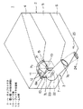
図1〜図2は本発明に係る電気接続箱の止水構造の一実施形態を示す概要図である。
【0018】
図1の如く、電気接続箱1は合成樹脂製の接続箱本体2とハーネスプロテクタ(以下プロテクタと言う)3とを備え、接続箱本体2は上カバー4と主カバー(中間カバー)5と下カバー6とで構成され、主カバー5にプロテクタ3が上方からスライド式に装着され、主カバー5の内側にはブロック部(図示せず)が装着され、ブロック部にはヒューズやリレーといった電気部品(図示せず)が装着されている。各カバー4〜6は係止手段(図示せず)で着脱自在に固定されている。
【0019】
プロテクタ3は筒状部7と、筒状部7の長手方向中間部に一体に形成された鍔状の垂直な覆い板(中間の鍔壁)8とで構成され、筒状部7は略L字状に屈曲し、先端側7aが水平よりも少し下向きに傾斜している。リレーやヒューズ等の複数の電気部品に接続した複数の電線(ワイヤハーネス)が筒状部7内に挿通されて外部に導出される。
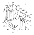
【0020】
図2にも示す如く、プロテクタ3の筒状部7は、主カバー5内に収容される基部側の筒状部分7bが上向きに湾曲状ないし傾斜状に屈曲されている。この上向きの屈曲部分7bの前側に垂直な覆い板8が位置している。覆い板8は左右両側と下側とに略U字状の鍔状のスライド係合部8aを有し、スライド係合部8aが主カバー5の略U字状の開口の周囲のガイド部10にスライド式に係合している。覆い板8の上端はガイド部10の上端とほぼ同一高さに位置している。
【0021】
図1,図2の如く、電気接続箱1の止水構造として、主カバー5にプロテクタ3の基部側の部分(上向きの屈曲部分)7bを収容するプロテクタ収容部11が一体に形成され、プロテクタ収容部11は左右の垂直な壁部12,13(右側の壁部13は主カバー5の外壁を兼ねている)と、底側(下側)の水平方向の壁部14(図2)と、後側の垂直な壁部である止水壁15とを備えている。後側とはプロテクタ3の導出方向を前側と定義した場合の方向である。
【0022】
図2の如く止水壁15はプロテクタ3の基部側の上向き屈曲部7bにおけるハーネス挿通孔16の開口17の下端17aとほぼ同じ高さまで延びている。プロテクタ3の開口17の端縁には下向きの垂直な鍔壁18が設けられ、鍔壁18と止水壁15との間に少しの隙間19が形成されている。鍔壁18はプロテクタ3の下側の長手方向の垂直なリブ板20に直交して続いている。そして、止水壁15に隣接(近接)して主カバー5のプロテクタ収容部11の底壁14に水抜き孔(第一の水抜き孔)21が設けられている。図1の如く主カバー5のプロテクタ収容部11の下側は切欠されて外側に開放され、下カバー6で覆われている。
【0023】
また、図2においてプロテクタ3の垂直な覆い板8をスライド係合させる主カバー5の凹状のガイド部10の底部(最下部)に水抜き孔(第二の水抜き孔)22が設けられている。ガイド部10の底面はプロテクタ収容部11の底壁面よりも低く位置している。
【0024】
さらに、プロテクタ3の覆い板8の後端面に続いて筒状部7に水抜き孔(第三の水抜き孔)23が設けられている。覆い板8は後側の上向き屈曲部7bと前側の短い水平部分7cとの境界に位置している。
【0025】
図2の矢印Aの如くプロテクタ3の覆い板8と主カバー5のガイド部10との間に浸入した水はガイド部10の水抜き孔22から主カバー5の外側すなわちプロテクタ収容部11の外側に排出される。また、矢印Bの如く外部から図1のプロテクタ3の先端開口7aあるいは電線24(図1)を伝わってプロテクタ3内に浸入した水は、先ずプロテクタ中間の水抜き孔23からプロテクタ外に排出され、次いでガイド部10の水抜き孔22又は収容部11の底壁14の水抜き孔21から主カバー5の外側に排出される。プロテクタ3の上向きの屈曲部7bの途中まで浸入した水は自重で屈曲部7bの内面に沿って落下して同じくプロテクタの水抜き孔23からガイド部10の水抜き孔22を経て主カバー5の外側に排出される。
【0026】
さらに、矢印Cの如く筒状部7に沿って上向きの屈曲部7bの頂部である開口端17まで達した水は止水壁15に当たって止水壁15と下向きの鍔壁18との間の隙間19に沿って(止水壁15及び鍔壁18を伝わって)スムーズに落下し、鍔壁18の直下の底壁14の水抜き孔21から主カバー5の外側に排出される。
【0027】
これら主カバー5の外側に排出された水は図1の下カバー6の最下部の水抜き孔25から電気接続箱1の外部に排出される。下カバー6にはリレーやヒューズ等の電気部品が配置されていないので、下カバー6内に水滴が落下してもショートや錆等の問題は何ら生じない。
【0028】
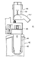
図3は主カバー5のプロテクタ収容部11の詳細図、図4はプロテクタ3の詳細図(図1とは上下を逆にして示している)、図5は主カバー5にプロテクタ3を装着した状態を示す詳細な断面図である。
【0029】
図3の如く、主カバー5のガイド部10は内外の板厚方向の二重壁26と、二重壁26の間の周壁27とでガイド溝(符号27で代用する)を構成し、周壁27の底部中央に前記水抜き孔22が形成されている。ガイド部10は左右両側の垂直な壁部12,13に直交して続き(右側の壁部13は主カバー5の外壁となっている)、両側の垂直な壁部12,13の間に底側の水平な壁部14と後側の垂直な止水壁15とが直交して続き、前側のガイド部10と両側の壁部12,13と底側の壁部14と後側の止水壁15とで略矩形状のプロテクタ収容部11が構成されている。
【0030】
止水壁15は左右の壁部12,13よりも低く形成されている。底壁14は前半14aが高く、後半14bが低くというように段付きとなっており、底壁14の中央に円弧状の凹部14cが形成され、凹部14cの最下部分に止水壁直下の水抜き孔21が左右一対設けられている。外部から底壁14に浸入した水は低い凹部14cに集められ、中央の水抜き孔21からプロテクタ収容部11の外側に排出される。
【0031】
底壁14の前半部分14aにはプロテクタ係止用の支柱28が左右一対対称に立設され、支柱28は外面側に係止凹部28aを有し、支柱28の上端が水平な係止壁28bとなっている。
【0032】
図4の如く、プロテクタ3は筒状部7や覆い板8の高さ方向ほぼ中央から上下に分割可能であり、係止枠部29と係合突起40といった係止手段で上下の分割部材3a,3bが相互に結合されている。図4では下側の水抜き孔23を図示するべく、使用形態とは上下逆に図示している。
【0033】
筒状部7の上向きの屈曲部7bにおいて上側の分割部材3aに図3の係止用の支柱28に対する係合用の断面略コの字状の支柱30が垂下形成され、係合用の支柱30は上向きの可撓性の係合アーム31を有し、係合アーム31の上端に内向きの係合突起31aが形成されている。プロテクタ3の装着時に両支柱28,30がスライド係合しつつ係合突起31aが図3の係止凹部28aに係合する。
【0034】
下側の分割部材3bの上向き屈曲部7bの底部中央に垂直方向のリブ板20が設けられ、リブ板20は開口端の鍔壁18に直交して続き、リブ板20の両側で垂直な覆い壁8の後端面に続いて一対の水抜き孔23が設けられている。屈曲部7bは覆い壁8を起点として上向きに屈曲し、水抜き孔23は起点側の最下部に位置している。水抜き孔23はプロテクタ3の装着状態で図3のガイド部10内の水抜き孔22の上側の近傍に位置する。覆い壁8から前方(プロテクタ収容部11の外側)に突出した筒状部分(符号7aで代用する)は下向きに傾斜している。
【0035】
垂直なリブ板20で図3のプロテクタ収容部11内の空間が区画(二分)され、収容部底壁14の一対の水抜き孔21が左右に二分される(一対の水抜き孔21の間にリブ板20が位置する)。これによって、プロテクタ収容部(収容空間)11の左右何れかに入った水滴は、二分された狭いスペース内で迅速に水抜き孔21から排出される。
【0036】
図5の如く、プロテクタ3を主ケース5に装着した状態で、止水壁15と鍔壁18とは同一高さに位置し、止水壁15と鍔壁18との間に隙間19が構成され、鍔壁18の下端と底壁14の水抜き孔21との間に隙間31が構成され、ガイド部10と覆い壁8との間に隙間32が構成される。水滴は各隙間19,31,32を通ってプロテクタ収容部11の各水抜き孔21,22に達し、迅速に排出される。鍔壁直下の水抜き孔21から排出された水は収容部下側の枠状の壁部33の内面に沿って下カバー6内に流れ落ちる。下カバー6があるから、水抜き孔21からの水の逆流(外部から水抜き孔21に水が入ること)が防止される。
【0037】
図5で符号34は上カバーを示す。上カバー34は主カバー5のガイド部10に続く上側のガイド部35を有し、上側のガイド部35は内側の防水パッキンで覆い壁8の上端部に密着する。ワイヤハーネス(複数本の電線)24はプロテクタ3の上向きの屈曲部7bを経て主カバー5の内側で下向きに屈曲しつつブロック部(図示せず)のヒューズやリレー等の電気部品に接続される。
【0038】
プロテクタ3の上向きの屈曲部7bにより、外部からの水が主カバー5内に浸入しにくくなっている。プロテクタ収容部11によっても、主カバー5内への水の浸入が防止されている。それに加えて、プロテクタ3の水抜き孔23やプロテクタ収容部11の止水壁15や各水抜き孔21,22によって主カバー5内への水の浸入が確実に防止されている。
【0039】
なお、上記した止水構造は主カバー5と上下カバー4,6のある接続箱本体2に限らず、下カバーを一体化した主カバーと上カバーとで成る接続箱本体においても適用可能である。
【0040】
【発明の効果】
以上の如く、請求項1記載の発明によれば、接続箱本体内に浸入しようとした水が止水壁によって阻止されるから、接続箱本体内のヒューズやリレー等の電気部品や電子ユニットや回路基板等にショートや錆等の悪影響を与えることが防止され、電気接続箱の品質が永続的に確保される。
【0041】
また、接続箱本体内に浸入しようとした水が鍔壁と止水壁との間の隙間に導かれてスムーズに落下するから、水の排出効率及び確実性が高まり、止水性が向上し、電気接続箱内の電気部品や電子部品等の水による悪影響が確実に防止される。
【0042】
請求項2記載の発明によれば、止水壁や鍔壁に沿って落下した水が下側の壁部の第一の水抜き孔から外側に排出されるから、電気接続箱内の電気部品や電子部品等への水分による悪影響が一層確実に防止され、電気接続箱の経時的品質が一層確実に保持される。
【0043】
請求項3記載の発明によれば、止水壁や鍔壁に沿って落下した水が直ちに水抜き孔から外側に排出されるから、水による電気接続箱内の悪影響が一層確実に防止され、電気接続箱の経時的品質が一層確実に保持される。
【0044】
請求項4記載の発明によれば、ハーネスプロテクタの開口端まで達する水が上向きの屈曲部で少なく抑えられるから、強い勢いでハーネスプロテクタ内に水が流入した場合でも、上記止水壁や鍔壁によって確実に阻止され、電気接続箱の経時的品質が確保される。
【0045】
請求項5記載の発明によれば、ハーネスプロテクタの開口下端から接続箱本体内に浸入しようとする水が止水壁の上端に当たり、止水壁や鍔壁の壁面に沿ってあるいは止水壁と鍔壁との間の隙間に導かれてスムーズに落下するから、ワイヤハーネスの挿通を邪魔することなく、接続箱本体内への水の浸入を確実に防止することができる。
【0046】
請求項6記載の発明によれば、鍔壁とガイド部との間から接続箱本体内に浸入しようとする水が第二の水抜き孔から外側に排出され、ガイド部側からの水の浸入にも確実に対処できるから、接続箱本体内への水の浸入が確実に防止され、電気接続箱の経時的品質が確実に維持される。
【0047】
請求項7記載の発明によれば、たとえ大量の水が一気に浸入した場合でも、プロテクタ収容部内に水が留められることで、第一及び/又は第二の水抜き孔から確実に外側に排出され、止水性が確保される。
【0048】
請求項8記載の発明によれば、ハーネスプロテクタ内に流入した水が端部開口に達するまでの間で第三の水抜き孔からプロテクタ外に排出され、第一及び/又は第二の水抜き孔から外側に排出されるから、止水性が一層向上し、電気接続箱の経時的品質が一層高められる。
【図面の簡単な説明】
【図1】本発明に係る電気接続箱の止水構造の一実施形態の概要を示す全体斜視図である。
【図2】同じく止水構造の概要を示す要部縦断面図である。
【図3】止水構造を有する主カバーのプロテクタ収容部の一実施形態を示す斜視図である。
【図4】プロテクタの一実施形態を示す斜視図である。
【図5】プロテクタを主カバーに装着した状態を示す縦断面図である。
【図6】従来の電気接続箱の止水構造の一形態を示す分解正面図である。
【図7】同じく組付状態を示す横断面図である。
【符号の説明】
2 接続箱本体
3 ハーネスプロテクタ
7b 上向き屈曲部
8 覆い壁(中間の鍔壁)
10 ガイド部
11 プロテクタ収容部
12,13 両側の壁部
14 下側の壁部(底壁)
15 止水壁
17a 開口下端
18 鍔壁
19 隙間
21 第一の水抜き孔
22 第二の水抜き孔
23 第三の水抜き孔[0001]
BACKGROUND OF THE INVENTION
The present invention relates to a water stop structure for an electrical junction box that prevents water from entering from the protector into the junction box body in an electrical junction box having a harness protector attached to the junction box body.
[0002]
[Prior art]
FIGS. 6-7 shows one form of the water stop structure of the conventional electrical junction box (refer patent document 1).
[0003]
In this structure, a
[0004]
An
[0005]
[Patent Document 1]
JP-A-8-322128 (
[0006]
[Problems to be solved by the invention]
However, in the above conventional structure, there is no problem in the location of the
[0007]
In view of the above points, the present invention allows the inner part of the main cover, i.e., the electrical component to be inserted even if the water jumps into the protector, for example, or enters between the cover plate (wall) and the guide part. It is an object of the present invention to provide a water stop structure for an electrical junction box that can reliably prevent water from entering the block portion side to be mounted.
[0008]
[Means for Solving the Problems]
In order to achieve the above object, a water stop structure for an electrical junction box according to the present invention includes a harness protector attached to a guide portion of a junction box body, and the junction box body is opposed to an end portion of the harness protector. A waterstop wall is provided , a downward wall is provided on the lower end side of the opening on the end side of the harness protector, the wall and the waterstop wall are opposed to each other, and the wall A water guiding gap is provided between the water blocking wall and water that has entered the harness protector is guided along the inner surface of the harness protector from the opening to the gap .
With the above configuration, water entering the harness protector tries to enter the junction box body along the lower inner surface of the harness protector, but hits the water blocking wall before entering the junction box body and enters the junction box body. Intrusion is prevented. The water that hits the water blocking wall falls along the outer surface of the water blocking wall and is discharged to the outside through, for example, a drain hole. Alternatively, it is prevented from being accumulated at the lower end side of the water blocking wall and evaporating and entering the junction box body as water droplets.
[0009]
Moreover, the water which tried to infiltrate into the junction box main body from the opening edge part of a harness protector is guide | induced to the clearance gap between a wall and a water stop wall, and falls smoothly. Fine water drops fall along the inner surface of the wall. Large water drops fall along both the inner surface of the dredging wall and the outer surface of the water blocking wall. The dropped water is discharged by drain holes or evaporation as described above.
[0010]
The water stop structure of the electrical junction box according to
With the above-described configuration, water that has dropped along the water blocking wall or dredging wall is discharged to the outside from the first drain hole of the lower wall portion, and water droplets are prevented from accumulating on the lower wall portion. .
[0011]
The water stop structure of the electrical junction box according to
By the said structure, the water which fell along the water stop wall or the dredging wall is immediately discharged | emitted from a drain hole to the outside, and drainage property improves further.
[0012]
The water stop structure of the electrical junction box according to
With the above configuration, since the inner surface of the harness protector is inclined upward, even if water flows into the harness protector, it falls back along the inclined surface until reaching the opening of the harness protector, and the outside from the opening. The outflow of water into the water is suppressed.
[0013]
The water stop structure of the electrical junction box according to
By the said structure, the electric wire penetrated in the harness protector is smoothly introduce | transduced in a junction box main body, without interfering with a water stop wall. Since the opening lower end of the harness protector and the upper end of the water stop wall are at the same height, the water entering the junction box body from the lower end of the opening hits the upper end of the water stop wall and runs along the outer surface of the water stop wall. It will fall and be surely prevented from entering the junction box body. Water falling from the lower end of the opening falls smoothly along the wall. Or it is guide | induced to the clearance gap between a water stop wall and a wall from an opening lower end, and is discharged | emitted reliably.
[0014]
The water stop structure of the electrical junction box according to
With the above configuration, the water to be infiltrated into the junction box body from between the wall and the guide part is collected along the guide part and the wall and at the lowermost part of the guide part, and outward from the second drain hole. Discharged. Thereby, the penetration | invasion of the water into a junction box main body from between a wall and a guide part is prevented. Should the like if water is large, when the flow along the lower side of the wall portion of the guide portion inside without being discharged from the second drainage holes (Claim 2), the first of
[0015]
The water stop structure of the electrical junction box according to
With the above configuration, a frame-shaped protector accommodating portion surrounded by four sides is formed in the junction box body, and water that has entered the protector accommodating portion is retained in the protector accommodating portion to prevent entry into the junction box body. The water in the protector housing is discharged outward from the first and / or second drain holes.
[0016]
The water stop structure of the electrical junction box according to claim 8 is the water stop structure of the electrical junction box according to any one of
With the above configuration, the water flowing into the harness protector is discharged out of the protector from the third drain hole until the end opening is reached, and from the first drain hole and / or the second drain hole. Discharged to the outside. The combination of the third drain hole and the upward bent portion described in
[0017]
DETAILED DESCRIPTION OF THE INVENTION
Hereinafter, embodiments of the present invention will be described in detail with reference to the drawings.
1 to 2 are schematic views showing an embodiment of a water stop structure for an electrical junction box according to the present invention.
[0018]
As shown in FIG. 1, the
[0019]
The
[0020]
As shown in FIG. 2, the
[0021]
As shown in FIGS. 1 and 2, as the water stop structure of the
[0022]
As shown in FIG. 2, the
[0023]
In FIG. 2, a drain hole (second drain hole) 22 is provided at the bottom (lowermost part) of the
[0024]
Further, a drain hole (third drain hole) 23 is provided in the
[0025]
The water that has entered between the cover plate 8 of the
[0026]
Further, the water that reaches the opening
[0027]
The water discharged to the outside of the
[0028]
3 is a detailed view of the
[0029]
As shown in FIG. 3, the
[0030]
The
[0031]
In the first half portion 14a of the
[0032]
As shown in FIG. 4, the
[0033]
In the upward
[0034]
A
[0035]
The space in the
[0036]
As shown in FIG. 5, with the
[0037]
In FIG. 5,
[0038]
The upward
[0039]
The water stop structure described above can be applied not only to the
[0040]
【The invention's effect】
As described above, according to the first aspect of the present invention, the water that is about to enter the junction box body is blocked by the water blocking wall, so that electrical components such as fuses and relays in the junction box body, electronic units, It is possible to prevent the circuit board or the like from being adversely affected by short circuit or rust, and to ensure the quality of the electrical junction box permanently.
[0041]
In addition, the water that is about to enter the junction box body is smoothly guided by the gap between the dredging wall and the water blocking wall and falls smoothly. The adverse effects of water on the electrical and electronic components in the electrical junction box are reliably prevented.
[0042]
According to invention of
[0043]
According to the invention described in
[0044]
According to invention of
[0045]
According to invention of
[0046]
According to invention of
[0047]
According to the seventh aspect of the present invention, even when a large amount of water intrudes at once, the water is retained in the protector accommodating portion, so that the water is surely discharged to the outside from the first and / or second drain holes. , Waterproofness is ensured.
[0048]
According to invention of Claim 8, the water which flowed in in the harness protector is discharged | emitted out of a protector from a 3rd drain hole until it reaches an edge part opening, and 1st and / or 2nd drain Since the water is discharged from the hole to the outside, the water stopping property is further improved, and the quality of the electric junction box with time is further improved.
[Brief description of the drawings]
FIG. 1 is an overall perspective view showing an outline of an embodiment of a water stop structure for an electrical junction box according to the present invention.
FIG. 2 is a longitudinal sectional view of an essential part showing an outline of a water stop structure.
FIG. 3 is a perspective view showing an embodiment of a protector accommodating portion of a main cover having a water stop structure.
FIG. 4 is a perspective view showing an embodiment of a protector.
FIG. 5 is a longitudinal sectional view showing a state in which the protector is mounted on the main cover.
FIG. 6 is an exploded front view showing one embodiment of a water stop structure of a conventional electric junction box.
FIG. 7 is a cross-sectional view showing the assembled state.
[Explanation of symbols]
2
10
15 Water stop wall 17a Opening
Claims (8)
Priority Applications (5)
| Application Number | Priority Date | Filing Date | Title |
|---|---|---|---|
| JP2003191835A JP4217552B2 (en) | 2003-07-04 | 2003-07-04 | Water stop structure of electrical junction box |
| CNB2004100621003A CN100446368C (en) | 2003-07-04 | 2004-07-05 | Waterproof structure of electrical junction box |
| DE102004032481A DE102004032481B4 (en) | 2003-07-04 | 2004-07-05 | Water barrier structure of an electrical connection box |
| CNU2004200678933U CN2770175Y (en) | 2003-07-04 | 2004-07-05 | Water insulating structure for electric junction box |
| US10/883,971 US6911600B2 (en) | 2003-07-04 | 2004-07-06 | Water-stop structure of electric connection box |
Applications Claiming Priority (1)
| Application Number | Priority Date | Filing Date | Title |
|---|---|---|---|
| JP2003191835A JP4217552B2 (en) | 2003-07-04 | 2003-07-04 | Water stop structure of electrical junction box |
Publications (2)
| Publication Number | Publication Date |
|---|---|
| JP2005027457A JP2005027457A (en) | 2005-01-27 |
| JP4217552B2 true JP4217552B2 (en) | 2009-02-04 |
Family
ID=33549846
Family Applications (1)
| Application Number | Title | Priority Date | Filing Date |
|---|---|---|---|
| JP2003191835A Expired - Fee Related JP4217552B2 (en) | 2003-07-04 | 2003-07-04 | Water stop structure of electrical junction box |
Country Status (4)
| Country | Link |
|---|---|
| US (1) | US6911600B2 (en) |
| JP (1) | JP4217552B2 (en) |
| CN (2) | CN100446368C (en) |
| DE (1) | DE102004032481B4 (en) |
Families Citing this family (25)
| Publication number | Priority date | Publication date | Assignee | Title |
|---|---|---|---|---|
| JP4217552B2 (en) * | 2003-07-04 | 2009-02-04 | 矢崎総業株式会社 | Water stop structure of electrical junction box |
| JP5581803B2 (en) * | 2010-05-19 | 2014-09-03 | 住友電装株式会社 | connector |
| JP5747633B2 (en) * | 2010-08-02 | 2015-07-15 | 富士電機株式会社 | Electronics |
| FR2965448B1 (en) * | 2010-09-27 | 2014-03-28 | Legrand France | ELECTRICAL APPARATUS SEALED |
| WO2012098882A1 (en) * | 2011-01-20 | 2012-07-26 | パナソニック株式会社 | Ceiling-embedded ventilation fan |
| JP5800556B2 (en) * | 2011-04-20 | 2015-10-28 | 矢崎総業株式会社 | Electric junction box wire cover waterproof structure |
| JP5947648B2 (en) * | 2012-07-25 | 2016-07-06 | 矢崎総業株式会社 | Water drainage structure for wire protection members |
| JP6095062B2 (en) * | 2013-05-20 | 2017-03-15 | 矢崎総業株式会社 | Electrical junction box |
| DE102014101579A1 (en) * | 2014-02-07 | 2015-08-13 | Huf Hülsbeck & Fürst Gmbh & Co. Kg | Line connection arrangement for a vehicle component |
| JP2016210214A (en) * | 2015-04-30 | 2016-12-15 | 住友電装株式会社 | Grommet bracket |
| JP6694293B2 (en) * | 2016-02-18 | 2020-05-13 | 本田技研工業株式会社 | Electrical component waterproof structure |
| CN105591291B (en) * | 2016-02-19 | 2018-04-27 | 四川汉舟电气股份有限公司 | A kind of electrical energy metering tank |
| US9742169B1 (en) * | 2016-06-28 | 2017-08-22 | Sumitomo Wiring Systems, Ltd. | Junction box assemblies with sequentially elevated openings |
| CN108242788B (en) * | 2016-12-27 | 2020-09-08 | 隗阳 | Supporting water-blocking power supply junction box structure |
| JP6767919B2 (en) * | 2017-04-25 | 2020-10-14 | 矢崎総業株式会社 | Electrical junction box and wire harness |
| JP6691073B2 (en) * | 2017-04-25 | 2020-04-28 | 矢崎総業株式会社 | Electrical connection box and wire harness |
| JP6660914B2 (en) * | 2017-04-27 | 2020-03-11 | 矢崎総業株式会社 | Electrical junction box and wire harness |
| JP6582016B2 (en) * | 2017-05-23 | 2019-09-25 | 矢崎総業株式会社 | Electrical junction box |
| CN108954739A (en) * | 2018-08-24 | 2018-12-07 | 珠海格力电器股份有限公司 | Electrical box, electrical box assembly and air conditioner |
| JP6797875B2 (en) * | 2018-10-03 | 2020-12-09 | 住友電装株式会社 | Electrical junction box |
| CN112154717A (en) * | 2019-04-10 | 2020-12-29 | 三菱电机株式会社 | Power conversion device |
| JP7163245B2 (en) * | 2019-04-25 | 2022-10-31 | 矢崎総業株式会社 | Electrical Junction Box and Wire Harness |
| JP7293074B2 (en) * | 2019-09-30 | 2023-06-19 | 矢崎総業株式会社 | Electrical Junction Box and Wire Harness |
| DE102023114857A1 (en) | 2023-06-06 | 2024-12-12 | Audi Aktiengesellschaft | Water-protected housing for electronic components, designed for arrangement in an aggregate compartment of a motor vehicle |
| CN120999493B (en) * | 2025-10-21 | 2025-12-30 | 凯普电子(昆山)有限公司 | Multifunctional four-way waterproof junction box |
Family Cites Families (14)
| Publication number | Priority date | Publication date | Assignee | Title |
|---|---|---|---|---|
| JPS5918588Y2 (en) | 1978-02-10 | 1984-05-29 | 株式会社ニフコ | Cable holder |
| JPH07203616A (en) | 1993-12-29 | 1995-08-04 | Sumitomo Wiring Syst Ltd | Fixing structure of wiring harness of electrical connection box |
| JP2981132B2 (en) | 1994-11-07 | 1999-11-22 | 矢崎総業株式会社 | Protector |
| JP2947460B2 (en) | 1994-12-14 | 1999-09-13 | 矢崎総業株式会社 | Protector |
| JPH08322128A (en) * | 1995-05-29 | 1996-12-03 | Yazaki Corp | Electric connection box with electric wire cover |
| JPH10224053A (en) | 1997-02-12 | 1998-08-21 | Funai Electric Co Ltd | Wiring device |
| JP2001063490A (en) * | 1999-08-25 | 2001-03-13 | Yazaki Corp | Grommet mis-assembly prevention structure |
| JP3319454B2 (en) * | 1999-12-14 | 2002-09-03 | 住友電装株式会社 | Door grommets |
| JP3562426B2 (en) * | 2000-03-07 | 2004-09-08 | 住友電装株式会社 | Waterproof structure of electrical junction box |
| JP3914399B2 (en) * | 2001-06-12 | 2007-05-16 | 矢崎総業株式会社 | Waterproof structure of electrical junction box |
| JP2003023715A (en) * | 2001-07-05 | 2003-01-24 | Yazaki Corp | Waterproof structure of electrical junction box |
| JP2003032856A (en) * | 2001-07-18 | 2003-01-31 | Yazaki Corp | Grommet |
| JP2003252356A (en) * | 2002-02-28 | 2003-09-10 | Mitsubishi Fuso Truck & Bus Corp | Waterproof case |
| JP4217552B2 (en) * | 2003-07-04 | 2009-02-04 | 矢崎総業株式会社 | Water stop structure of electrical junction box |
-
2003
- 2003-07-04 JP JP2003191835A patent/JP4217552B2/en not_active Expired - Fee Related
-
2004
- 2004-07-05 DE DE102004032481A patent/DE102004032481B4/en not_active Expired - Fee Related
- 2004-07-05 CN CNB2004100621003A patent/CN100446368C/en not_active Expired - Fee Related
- 2004-07-05 CN CNU2004200678933U patent/CN2770175Y/en not_active Expired - Lifetime
- 2004-07-06 US US10/883,971 patent/US6911600B2/en not_active Expired - Fee Related
Also Published As
| Publication number | Publication date |
|---|---|
| CN100446368C (en) | 2008-12-24 |
| JP2005027457A (en) | 2005-01-27 |
| DE102004032481A1 (en) | 2005-01-27 |
| CN1578037A (en) | 2005-02-09 |
| DE102004032481B4 (en) | 2007-01-18 |
| US6911600B2 (en) | 2005-06-28 |
| US20050045360A1 (en) | 2005-03-03 |
| CN2770175Y (en) | 2006-04-05 |
Similar Documents
| Publication | Publication Date | Title |
|---|---|---|
| JP4217552B2 (en) | Water stop structure of electrical junction box | |
| US9374916B2 (en) | Electrical junction box | |
| CN101874332A (en) | Electrical connection box | |
| JP5242326B2 (en) | Waterproof structure of electrical junction box | |
| US9204562B2 (en) | Electrical junction box | |
| JP2002369335A (en) | Double wall structure of electrical junction box | |
| JP4474463B2 (en) | Electrical junction box | |
| JP6904995B2 (en) | Electrical junction box | |
| JP2020080589A (en) | Housing, electric connection box, and wire harness | |
| JP5741945B2 (en) | Electrical junction box | |
| JP4063020B2 (en) | Drainage structure of electrical junction box | |
| JP5984717B2 (en) | Electrical junction box | |
| JP5626703B2 (en) | Electrical junction box | |
| JP4002801B2 (en) | Drainage structure of electrical junction box | |
| JP4662280B2 (en) | Louver for electrical equipment storage cabinet | |
| JP4096638B2 (en) | Drainage structure of waterproof cover of electrical junction box | |
| EP3826122B1 (en) | Liquid discharge structure | |
| JP2017108493A (en) | Electrical junction box and wire harness | |
| JP5061949B2 (en) | In-vehicle electrical junction box | |
| JP2001238328A (en) | Electric junction box | |
| CN101138138A (en) | electrical connection box | |
| JP2003009349A (en) | Waterproof structure of electrical junction box | |
| JP2019221080A (en) | Wire case | |
| JP2010051161A (en) | Electric connecting box for vehicle | |
| JP7832047B2 (en) | Electrical junction box |
Legal Events
| Date | Code | Title | Description |
|---|---|---|---|
| A621 | Written request for application examination |
Free format text: JAPANESE INTERMEDIATE CODE: A621 Effective date: 20060126 |
|
| A977 | Report on retrieval |
Free format text: JAPANESE INTERMEDIATE CODE: A971007 Effective date: 20071213 |
|
| A131 | Notification of reasons for refusal |
Free format text: JAPANESE INTERMEDIATE CODE: A131 Effective date: 20080212 |
|
| A521 | Request for written amendment filed |
Free format text: JAPANESE INTERMEDIATE CODE: A523 Effective date: 20080409 |
|
| TRDD | Decision of grant or rejection written | ||
| A01 | Written decision to grant a patent or to grant a registration (utility model) |
Free format text: JAPANESE INTERMEDIATE CODE: A01 Effective date: 20081104 |
|
| A01 | Written decision to grant a patent or to grant a registration (utility model) |
Free format text: JAPANESE INTERMEDIATE CODE: A01 |
|
| A61 | First payment of annual fees (during grant procedure) |
Free format text: JAPANESE INTERMEDIATE CODE: A61 Effective date: 20081110 |
|
| R150 | Certificate of patent or registration of utility model |
Free format text: JAPANESE INTERMEDIATE CODE: R150 |
|
| FPAY | Renewal fee payment (event date is renewal date of database) |
Free format text: PAYMENT UNTIL: 20111114 Year of fee payment: 3 |
|
| FPAY | Renewal fee payment (event date is renewal date of database) |
Free format text: PAYMENT UNTIL: 20121114 Year of fee payment: 4 |
|
| FPAY | Renewal fee payment (event date is renewal date of database) |
Free format text: PAYMENT UNTIL: 20121114 Year of fee payment: 4 |
|
| FPAY | Renewal fee payment (event date is renewal date of database) |
Free format text: PAYMENT UNTIL: 20131114 Year of fee payment: 5 |
|
| R250 | Receipt of annual fees |
Free format text: JAPANESE INTERMEDIATE CODE: R250 |
|
| S111 | Request for change of ownership or part of ownership |
Free format text: JAPANESE INTERMEDIATE CODE: R313117 |
|
| R350 | Written notification of registration of transfer |
Free format text: JAPANESE INTERMEDIATE CODE: R350 |
|
| LAPS | Cancellation because of no payment of annual fees |