EP1108492A2 - Method and device for connecting the ends of metal strips by resistance welding - Google Patents
Method and device for connecting the ends of metal strips by resistance welding Download PDFInfo
- Publication number
- EP1108492A2 EP1108492A2 EP00122926A EP00122926A EP1108492A2 EP 1108492 A2 EP1108492 A2 EP 1108492A2 EP 00122926 A EP00122926 A EP 00122926A EP 00122926 A EP00122926 A EP 00122926A EP 1108492 A2 EP1108492 A2 EP 1108492A2
- Authority
- EP
- European Patent Office
- Prior art keywords
- perforation
- welding
- strips
- resistance welding
- layer
- Prior art date
- Legal status (The legal status is an assumption and is not a legal conclusion. Google has not performed a legal analysis and makes no representation as to the accuracy of the status listed.)
- Withdrawn
Links
Images


Classifications
-
- B—PERFORMING OPERATIONS; TRANSPORTING
- B23—MACHINE TOOLS; METAL-WORKING NOT OTHERWISE PROVIDED FOR
- B23K—SOLDERING OR UNSOLDERING; WELDING; CLADDING OR PLATING BY SOLDERING OR WELDING; CUTTING BY APPLYING HEAT LOCALLY, e.g. FLAME CUTTING; WORKING BY LASER BEAM
- B23K11/00—Resistance welding; Severing by resistance heating
- B23K11/002—Resistance welding; Severing by resistance heating specially adapted for particular articles or work
- B23K11/0026—Welding of thin articles
-
- B—PERFORMING OPERATIONS; TRANSPORTING
- B23—MACHINE TOOLS; METAL-WORKING NOT OTHERWISE PROVIDED FOR
- B23K—SOLDERING OR UNSOLDERING; WELDING; CLADDING OR PLATING BY SOLDERING OR WELDING; CUTTING BY APPLYING HEAT LOCALLY, e.g. FLAME CUTTING; WORKING BY LASER BEAM
- B23K11/00—Resistance welding; Severing by resistance heating
- B23K11/16—Resistance welding; Severing by resistance heating taking account of the properties of the material to be welded
- B23K11/163—Welding of coated materials
-
- B—PERFORMING OPERATIONS; TRANSPORTING
- B23—MACHINE TOOLS; METAL-WORKING NOT OTHERWISE PROVIDED FOR
- B23K—SOLDERING OR UNSOLDERING; WELDING; CLADDING OR PLATING BY SOLDERING OR WELDING; CUTTING BY APPLYING HEAT LOCALLY, e.g. FLAME CUTTING; WORKING BY LASER BEAM
- B23K2101/00—Articles made by soldering, welding or cutting
- B23K2101/16—Bands or sheets of indefinite length
Definitions
- the invention relates to a method for connecting the Ends of two strips processed in a rolling mill made of metal, which on its top and / or bottom have layer adhering to them, by Resistance welding, where a welding device is on the surface assigned to it in the area of the ends the tapes are put on.
- the invention also relates to one for connecting the ends of such metal strips suitable device.
- the ends of the belt should be across their entire width are welded together, so are usually wheel-shaped, rotatably mounted electrodes used during welding along the respective edge of the strip be moved.
- a major advantage of resistance welding is there in that high welding speeds with relative simply trained and therefore inexpensive Allow welding fixtures to be achieved. This enables those needed to connect the ends of the tape Reduce production interruptions to a minimum.
- the disadvantage is that in resistance welding sufficient electrical contact between the electrodes and the strip ends to be welded must be in order to achieve a proper welding result.
- Tinder layer the attempt to resistance welding to be used for joining hot tapes with an unfavorable welding properties Tinder layer are shown that a proper weld connection only under large Difficulties can be created.
- the object of the invention is a method and specify a device with which also the safe Bonding with a layer adhering to them provided metal strips by resistance welding inexpensive way is possible.
- this problem is solved in that before Resistance welding the layer in the area with Perforations are provided in which during the Welding process the welded connection is generated.
- the resistance welding device there is sufficient contact between the resistance welding device and the respective Metal strip manufactured in that the Metal tape adhesive layer is provided with openings, in the area of which the surface of the metal strips is exposed.
- the Metal tape adhesive layer is provided with openings, in the area of which the surface of the metal strips is exposed.
- the perforation of the layer adhering to the metal band can be carried out inexpensively in a simple manner, since only the relevant layer has to be broken through got to. In this way, the cost of preparing the Strip ends to be welded for resistance welding reduced to a minimum so that the benefits of this Welding process also when joining with a layer provided metal strips can be used advantageously.
- the method according to the invention is particularly suitable for Joining the ends of steel hot strips in one Rolling mill to be processed without first having to oxide layer adhering to them. Especially when processing with such Steel strips provided with a layer of scale Use invention economically.
- ends of the tapes to be joined after perforating to get in contact with each other and then close weld.
- Welding in two consecutive times Work moves carried out.
- This has the advantage that Layers on both sides of the respective tape ends can be perforated.
- Another advantageous embodiment of the invention is characterized in that the perforation of the respective Layers of both ends of the tapes are done simultaneously. Regardless of whether the perforation of the layers is made before the tapes come into contact with each other brought in or while they are already in contact this procedure leads to another Shortening the process of connecting the tape ends time needed.
- the above is mentioned Task by a device for welding ends a metal tape, which with a stick on them Coated layer, solved with at least one Resistance welding device and with a Perforation device for perforating at least the Layer, which is in the range of generating weld on that surface of the Tapes adheres to which the resistance welding device is attached during the welding process.
- a device designed in this way can in particular Hot strips, which have a firmly adhering scale layer, through resistance welding in a cost-effective way connect.
- the one for welding can be further reduced time required in that at least one Perforation device under and one Perforation device over the conveyor belt path is arranged.
- the device of the invention can easily a simultaneous perforation of the freely accessible Layers on the top and bottom of the tapes be performed. For those applications where the perforation of the layer before the local assembly of the band ends, this can also save time be accomplished by having each end of the tapes one below and one above the funding path of the Belts arranged perforation device is assigned.
- One according to the invention can be particularly inexpensive Realize the device in that the Resistance welding device during the welding process in a manner known per se transversely to the conveying direction of the Bands is movable.
- this embodiment of the invention becomes the welding electrode of the resistance welding device guided along the end of the strip so that the welding process as such takes place locally.
- the welding parameters can be adjusted in this way and those practiced locally during welding Optimize contact forces in a simple way.
- the conditions during the Perforation can be optimized, even if the Perforation device transverse to the conveying direction of the belts is movable.
- the perforations can basically be done with anyone Device are generated that is suitable for a sufficient number of openings in the on the Break metal tape adhesive layer. Especially this can be done easily, for example accomplish that the perforations by means of a rotatably mounted wheel are generated. This can for example, moved under pressure over the layer be so high that the layer at least chipped from the metal strip in places. More even arranged openings of the layer can thereby be generate that on the circumference of the wheel bumps in evenly arranged, which are in the layer penetrate and create the openings.
- the device shown in Figures 1 to 5 is V1 for connecting the ends 1, 2 of two in the conveying direction F promoted by a rolling mill, not shown Hot strips W1, W2 determined on their respective surface 01.02 one from previous steps of Steel strip production originating scale layer firmly adheres.
- the device 1 has one above the hot strips W1, W2 arranged first carriage 3 'and one below the Hot strips W1, W2 arranged second carriage 3 ". Both Carriages 3 ', 3 "are coupled to one another in such a way that they together in a direction transverse to the conveying direction F. Direction of movement Q across the width of the hot strips W1, W2 are movable.
- the respective perforation device 4 ', 4 " is rotatable mounted on the housing 8 ', 8 "of the respective carriage 3', 3", disc-shaped wheel formed on its peripheral surface 9 not in each case at regular intervals shown surveys are arranged.
- actuator can Perforation device 4 ', 4 "in the vertical direction in a rest position raised ( Figures 4,5) or in a Working position are lowered ( Figures 2,3), in which them on the surface 01.02 of the respective metal strip W1, W2 sits.
- the respective resistance welding device 5 ', 5 " is after Kind of a rotatably mounted on the respective carriage 3 ', 3 " Electrode is formed and is not shown Energy supply fed. Also the Resistance welding device 5 ', 5 "can be used as well Not shown actuator in the vertical direction in a rest position raised ( Figures 2,3) or in a Working position are lowered ( Figures 4,5), in which they apply force to the one assigned to them Surface O1 or O2 of the respective hot strip W1, W2 is pressed.
- the respective upsetting device 6 ', 6 " is a roll formed, which are also in the respective housing 8 ', 8 " is stored. It can also move in a vertical direction Rest position raised ( Figures 2, 3) or in one Working position are lowered ( Figures 4,5), in which on the surface O1, O2 of the respective hot strip W1, W2 sits.
- each Surface 01.02 pressed perforation devices 4 ', 4 " roll on the surface in question for this purpose 01.02 and shape in the manner of a knurled wheel with their Elevations in the area of the end sections 14, 15 in the the surface 01.02 existing scale layers openings on. In the area of so generated at regular intervals Perforations are those under the scale layer lying surface of the hot strips W1, W2 exposed.
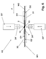
- the alternative device shown in Figures 6 to 8 V2 for connecting the ends 1, 2 of two hot strips W1, W2 also has two carriages 23 ', 23 "which correspond to the Carriage 3 ', 3 "of the example explained first in one Work train together in the direction of movement Q across Direction of conveyance F of the hot strips W1, W2 are movable.
- the carriages 23', 23" each carry one Perforation device 24 ', 24 ", one Resistance welding device 25 ', 25 “and one Upsetting device 26 ', 26 ".
- the carriages 23', 23” each have only one Perforation device 24 ', 24 ", the respective Perforation device 24 ', 24 “, the respective Resistance welding device 25 ', 25 “and the respective Compression device 26 ', 26 “of the carriage 23', 23” in one line one behind the other parallel to the edges 12, 13 of the ends 1, 2 are arranged and the respective perforation device 24 ', 24 "in the direction of a work train direction of travel Q seen before respective resistance welding device 25 ', 25 "arranged is.
- the respective perforation device 24 ', 24 " is again as rotatable on the housing 28 ', 28 "of the respective carriage 23 ', 23 "mounted disc-shaped wheel, on whose peripheral surface 29 each at regular intervals arranged here in detail surveys, not shown are.
- the Perforation device 24 ', 24 "also not shown adjusting device in the vertical direction in a rest position raised (Fig. 6) or in a Working position are lowered ( Figures 7,8), in which them on the surface 01.02 of the respective metal strip W1, W2 sits.
- the respective upsetting device 26 ', 26 " is like that before explained upsetting devices 6 ', 6 "as a roll trained, also in the respective housing 28 ', 28 "is mounted. It can also in the vertical direction raised to a rest position (Fig. 6) or in a Working position are lowered ( Figures 7,8), in which them on the surface O1, O2 of the respective metal strip W1, W2 sits.
- the ends 1, 2 of the hot strips W1, W2 are initially two Guide devices 30, 31 detected, spaced apart fixed and by means of a not shown Cutting device in the area of their ends 1,2 so cut that the mutually associated edges 12, 13 of Ends 1,2 have a clean, parallel course.
- resistance welding devices 25 ', 25 the reach the perforated point at which the Surface of the hot strips W1, W2 under the scale of the respective perforation device 24 ', 24 "exposed has a direct contact and it becomes generates heat necessary for welding. This is sufficient in this case, although perforation of the between the superimposed end sections 14, 15 existing scale layer has not taken place.
- the so generated weld seam is also lowered by the and seen in this direction Q behind Resistance welding devices 25 ', 25 "arranged respective upsetting device 26 ', 26 “upset so that The weld seam should be leveled.
Abstract
Description
Die Erfindung betrifft ein Verfahren zum Verbinden der Enden von zwei in einer Walzstraße verarbeiteten Bändern aus Metall, welche auf ihrer Ober- und/oder Unterseite eine auf ihnen haftende Schicht aufweisen, durch Widerstandsschweißen, bei dem eine Schweißeinrichtung auf die ihr jeweils zugeordnete Oberfläche im Bereich der Enden der Bänder aufgesetzt wird. Ebenso betrifft die Erfindung eine für das Verbinden der Enden derartiger Metallbänder geeignete Vorrichtung.The invention relates to a method for connecting the Ends of two strips processed in a rolling mill made of metal, which on its top and / or bottom have layer adhering to them, by Resistance welding, where a welding device is on the surface assigned to it in the area of the ends the tapes are put on. The invention also relates to one for connecting the ends of such metal strips suitable device.
Üblicherweise wird bei der Inline-Erzeugung von Metallbändern in einer Walzstraße das dem Bandanfang zugeordnete Ende eines neu in Bearbeitung zu nehmenden Bandes mit dem endseitigen Bandende des zuvor gewalzten Bandes verbunden. In der Praxis werden die Bandenden zu diesem Zweck miteinander verschweißt. Durch eine solche Verschweißung ist sichergestellt, daß das neu in Bearbeitung genommene Band sicher in die Walzstraße gezogen wird, ohne daß es dazu zusätzlicher Vorkehrungen oder einer größeren Unterbrechung des Produktionsbetriebes bedarf.Usually, the inline generation of Metal strips in a rolling mill that start the strip assigned end of a newly to be processed Strip with the end of the strip previously rolled Band connected. In practice, the band ends become too welded together for this purpose. By such Welding ensures that this is new in Machined tape safely pulled into the rolling mill without additional arrangements or a major interruption of production operations.
Für das Verschweißen der Bandenden von Metallbändern, die eine saubere Oberfläche aufweisen, wie es beispielsweise bei entzunderten Kaltbändern der Fall ist, eignen sich insbesondere Widerstandsschweißeinrichtungen. Diese Einrichtungen werden mit ihren Elektroden im Bereich der zu erzeugenden Schweißnaht jeweils auf die Oberfläche der leitfähigen Bänder mit oder ohne zusätzliche Krafteinwirkung aufgesetzt, so daß die zum Schweißen erforderliche Wärme durch den Stromfluß über den jeweils vorhandenen elektrischen Widerstand erzeugt wird.For welding the ends of metal strips have a clean surface, for example is the case with descaled cold strips especially resistance welding devices. This Institutions are using their electrodes in the area of the generating weld seam on the surface of the conductive tapes with or without additional Force applied, so that for welding heat required by the flow of electricity over each existing electrical resistance is generated.
Sollen die Bandenden dabei über ihre gesamte Breite miteinander verschweißt werden, so werden üblicherweise radförmige, drehbar gelagerte Elektroden verwendet, die während des Schweißens entlang der jeweiligen Bandendkante bewegt werden.The ends of the belt should be across their entire width are welded together, so are usually wheel-shaped, rotatably mounted electrodes used during welding along the respective edge of the strip be moved.
Ein wesentlicher Vorteil des Widerstandsschweißens besteht darin, daß sich hohe Schweißgeschwindigkeiten mit relativ einfach ausgebildeten und folglich kostengünstigen Schweißvorrichtungen erzielen lassen. Dies ermöglicht es, die für das Verbinden der Bandenden benötigten Produktionsunterbrechungen auf ein Minimum zu reduzieren. Nachteilig ist jedoch, daß beim Widerstandsschweißen ein ausreichender elektrischer Kontakt zwischen den Elektroden und den zu verschweißenden Bandenden gewährleistet sein muß, um ein ordnungsgemäßes Schweißergebnis zu erzielen.A major advantage of resistance welding is there in that high welding speeds with relative simply trained and therefore inexpensive Allow welding fixtures to be achieved. This enables those needed to connect the ends of the tape Reduce production interruptions to a minimum. The disadvantage, however, is that in resistance welding sufficient electrical contact between the electrodes and the strip ends to be welded must be in order to achieve a proper welding result.
Dementsprechend hat der Versuch, das Widerstandsschweißen für das Verbinden von Warmbändern zu verwenden, die mit einer ungünstige Schweißeigenschaften aufweisenden Zunderschicht behaftet sind, gezeigt, daß eine ordnungsgemäße Schweißverbindung nur unter großen Schwierigkeiten hergestellt werden kann. Accordingly, the attempt to resistance welding to be used for joining hot tapes with an unfavorable welding properties Tinder layer are shown that a proper weld connection only under large Difficulties can be created.
Zur Beseitigung dieser Schwierigkeiten ist vorgeschlagen worden, vor der Widerstandsverschweißung eine vollständige, großflächige Entzunderung der jeweiligen Bandenden vorzunehmen. Die dazu erforderlichen Maßnahmen führen jedoch dazu, daß die hinsichtlich der Kosten und der Arbeitsgeschwindigkeit gegenüber anderen Schweißverfahren, wie beispielsweise dem Lichtbogenschweißen, bestehenden Vorteile des Widerstandsschweißens eingebüßt werden.It is suggested to overcome these difficulties a complete, before resistance welding large descaling of the respective strip ends to make. Take the necessary measures however, that the in terms of cost and Working speed compared to other welding processes, such as arc welding Benefits of resistance welding are lost.
Die Aufgabe der Erfindung besteht darin, ein Verfahren und eine Vorrichtung anzugeben, mit denen auch das sichere Verbinden von mit einer auf ihnen haftenden Schicht versehenen Metallbändern durch Widerstandsschweißen auf kostengünstige Weise möglich ist.The object of the invention is a method and specify a device with which also the safe Bonding with a layer adhering to them provided metal strips by resistance welding inexpensive way is possible.
In Bezug auf ein Verfahren der eingangs erläuterten Art wird diese Aufgabe dadurch gelöst, daß vor dem Widerstandsschweißen die Schicht in dem Bereich mit Perforationen versehen wird, in welchem während des Schweißvorgangs die Schweißverbindung erzeugt wird.With regard to a method of the type described at the beginning this problem is solved in that before Resistance welding the layer in the area with Perforations are provided in which during the Welding process the welded connection is generated.
Gemäß der Erfindung wird ein ausreichender Kontakt zwischen der Widerstandsschweißeinrichtung und dem jeweiligen Metallband dadurch hergestellt, daß die auf den Metallbändern haftende Schicht mit Öffnungen versehen wird, in deren Bereich die Oberfläche der Metallbänder freiliegt. Auf diese Weise besteht an diesen Stellen während des Schweißvorgangs jeweils ein unmittelbarer Kontakt zwischen der Widerstandsschweißeinrichtung und dem Metallband. Überraschenderweise hat sich herausgestellt, daß durch die Vielzahl der durch die Perforierung der Schicht erzeugten Kontaktflächen des Metallbands ein für die notwendige Wärmeentwicklung ausreichender Stromfluß gewährleistet ist.According to the invention, there is sufficient contact between the resistance welding device and the respective Metal strip manufactured in that the Metal tape adhesive layer is provided with openings, in the area of which the surface of the metal strips is exposed. In this way, at these points during the Welding process a direct contact between each the resistance welding device and the metal band. Surprisingly, it has been found that the Plenty of those created by perforating the layer Contact areas of the metal band for the necessary Heat generation sufficient current flow is guaranteed.
Die Perforation der auf dem Metallband haftenden Schicht läßt sich auf einfache Weise kostengünstig durchführen, da dazu lediglich die betreffende Schicht durchbrochen werden muß. Auf diese Weise sind die Kosten der Vorbereitung der zu verschweißenden Bandenden für das Widerstandsschweißen auf ein Minimum reduziert, so daß sich die Vorteile dieses Schweißverfahrens auch beim Verbinden von mit einer Schicht versehenen Metallbändern vorteilhaft nutzen läßt.The perforation of the layer adhering to the metal band can be carried out inexpensively in a simple manner, since only the relevant layer has to be broken through got to. In this way, the cost of preparing the Strip ends to be welded for resistance welding reduced to a minimum so that the benefits of this Welding process also when joining with a layer provided metal strips can be used advantageously.
Besonders geeignet ist das erfindungsgemäße Verfahren zum Verbinden der Enden von Warmbändern aus Stahl, die in einer Walzstraße verarbeitet werden sollen, ohne zuvor von der auf ihnen haftenden Oxidschicht befreit worden zu sein. Insbesondere bei der Verarbeitung von mit einer derartigen Zunderschicht versehenen Stahlbändern läßt sich die Erfindung wirtschaftlich einsetzen.The method according to the invention is particularly suitable for Joining the ends of steel hot strips in one Rolling mill to be processed without first having to oxide layer adhering to them. Especially when processing with such Steel strips provided with a layer of scale Use invention economically.
Dabei ergeben sich besonders gute Schweißergebnisse, wenn die Schicht im Zuge des Perforierens mit regelmäßig angeordneten Öffnungen versehen wird. Durch die regelmäßige Anordnung der Perforationsöffnungen ist sichergestellt, daß es zu keinen Verwerfungen des Bandes aufgrund einer unregelmäßigen Ausbildung der Schweißnaht kommt. Diese könnten andernfalls im folgenden Walzprozeß das Walzergebnis verschlechtern oder zu einem vorzeitigen Verschleiß der in den Walzgerüsten eingesetzten Walzen führen. This gives particularly good welding results if the layer in the course of perforating with regular arranged openings is provided. Through the regular Arrangement of the perforation openings ensures that there is no warping of the tape due to any irregular formation of the weld seam comes. This could otherwise do that in the subsequent rolling process Rolling result deteriorate or premature Wear of the rollers used in the roll stands to lead.
Gemäß einer Variante der Erfindung ist es vorgesehen, die zu verbindenden Enden der Bänder nach dem Perforieren miteinander in Kontakt zu bringen und daran anschließend zu verschweißen. Bei dieser Ausgestaltung des erfindungsgemäßen Verfahrens werden das Perforieren und das Verschweißen in zwei zeitlich aufeinanderfolgenden Arbeitszügen durchgeführt. Dies hat den Vorteil, daß Schichten auf beiden Seiten der jeweiligen Bandenden perforiert werden können. Daraus ergeben sich insbesondere dann Vorteile, wenn die Bandenden zum Verschweißen überlappend aufeinandergelegt gelegt werden. Denn in diesem Fall können die zu verschweißenden Enden der Bänder sowohl auf der der Schweißeinrichtung zugeordneten Oberfläche als auch im Bereich der Flächen perforiert werden, in denen während des Schweißens ein unmittelbarer Kontakt zwischen ihnen besteht.According to a variant of the invention it is provided that ends of the tapes to be joined after perforating to get in contact with each other and then close weld. In this embodiment of the perforation and the inventive method Welding in two consecutive times Work moves carried out. This has the advantage that Layers on both sides of the respective tape ends can be perforated. This results in particular then advantages if the strip ends for welding overlapping one another. Because in this Case can be the ends of the tapes to be welded both on the surface assigned to the welding device as also be perforated in the area of the direct contact between during welding to them.
Eine hinsichtlich des Kostenaufwands weiter optimierte Alternative zu der Perforierung der beidseitig an den jeweiligen Bandenden vorhandenen Schichten besteht darin, daß die zu verbindenden Enden der Bänder vor dem Perforieren miteinander in Kontakt gebracht werden. In diesem Fall wird die Perforierung jeweils nur auf den Oberflächen der Metallbänder durchgeführt, auf welcher die Widerstandsschweißeinrichtung während des Schweißvorganges sitzt. Eine gezielte Perforation der nach dem Aufeinanderlegen nicht mehr zugänglichen Kontaktflächen zwischen den Metallbändern findet demgegenüber nicht statt. Überraschend hat sich jedoch gezeigt, daß der durch die Perforation der frei zugänglichen Oberflächen sichergestellte Kontakt zu der Widerstandsschweißeinrichtung in vielen Anwendungsfällen dennoch für die Erzeugung einer sicheren Schweißverbindung zwischen den Metallbändern ausreichend ist. Der besondere Vorzug dieser Variante der Erfindung besteht dabei darin, daß das Perforieren und Verschweißen in einem Arbeitszug erfolgen kann. Indem die Perforierung und die Verschweißung in einem solchen gemeinsamen Bewegungsablauf durchgeführt werden, läßt sich der für das Verbinden benötigte Zeitaufwand auf eine Minimum reduzieren.One further optimized in terms of cost Alternative to the perforation on both sides of the layers present at each band end consists of that the ends of the tapes to be connected before Perforations are brought into contact with each other. In In this case, the perforation is only on the Surfaces of the metal strips on which the Resistance welding device during the welding process sits. A targeted perforation after the Stacking contact areas that are no longer accessible in contrast, does not take place between the metal strips. Surprisingly, however, it has been shown that the Perforation of the freely accessible surfaces ensured contact to the Resistance welding device in many applications nevertheless for the creation of a secure welded connection between the metal strips is sufficient. The special one The advantage of this variant of the invention is that that perforating and welding in one operation can be done. By perforating and welding performed in such a common sequence of movements can be used for connecting Reduce time to a minimum.
Eine weitere vorteilhafte Ausgestaltung der Erfindung ist dadurch gekennzeichnet, daß die Perforierung der jeweiligen Schichten beider Enden der Bänder gleichzeitig erfolgt. Unabhängig davon, ob die Perforation der Schichten vorgenommen wird, bevor die Bänder in Kontakt miteinander gebracht werden oder während sie sich schon in Kontakt befinden, führt diese Vorgehensweise zu einer weiteren Verkürzung der für den Vorgang des Verbindens der Bandenden benötigten Zeit.Another advantageous embodiment of the invention is characterized in that the perforation of the respective Layers of both ends of the tapes are done simultaneously. Regardless of whether the perforation of the layers is made before the tapes come into contact with each other brought in or while they are already in contact this procedure leads to another Shortening the process of connecting the tape ends time needed.
Hinsichtlich der Vorrichtung wird die voranstehend genannte Aufgabe durch eine Vorrichtung zum Verschweißen von Enden eines Metallbandes, welches mit einer auf ihnen haftenden Schicht überzogen ist, gelöst, die mit mindestens einer Widerstandsschweißeinrichtung und mit einer Perforationseinrichtung zum Perforieren mindestens der Schicht ausgestattet ist, welche im Bereich der zu erzeugenden Schweißnaht auf derjenigen Oberfläche der Bänder haftet, auf der die Widerstandsschweißeinrichtung während des Schweißvorgangs aufgesetzt ist. Mit einer derart ausgebildeten Vorrichtung lassen sich insbesondere Warmbänder, die eine fest haftende Zunderschicht besitzen, durch eine Widerstandsschweißung auf kostengünstige Weise verbinden.With regard to the device, the above is mentioned Task by a device for welding ends a metal tape, which with a stick on them Coated layer, solved with at least one Resistance welding device and with a Perforation device for perforating at least the Layer, which is in the range of generating weld on that surface of the Tapes adheres to which the resistance welding device is attached during the welding process. With a device designed in this way can in particular Hot strips, which have a firmly adhering scale layer, through resistance welding in a cost-effective way connect.
Dabei ist es im Hinblick auf eine Optimierung der benötigten Zeiten vorteilhaft, wenn jedem der beiden zu verbindenden Enden der Bänder eine eigene Perforationseinrichtung zugeordnet ist.It is with a view to optimizing the times needed advantageous if either of the two too connecting ends of the bands their own Perforation device is assigned.
Weiter vermindern läßt sich der für das Verschweißen benötigte Zeitaufwand dadurch, daß jeweils mindestens eine Perforationseinrichtung unter und eine Perforationseinrichtung über dem Förderweg der Bänder angeordnet ist. Mit einer derart ausgestalteten erfindungsgemäßen Vorrichtung kann problemlos eine gleichzeitige Perforation der jeweils frei zugänglichen Schichten an der Ober- und Unterseite der Bänder durchgeführt werden. Für solche Anwendungsfälle, bei denen die Perforation der Schicht vor dem örtlichen Zusammenfügen der Bandenden erfolgen soll, kann dies ebenso zeitsparend dadurch bewerkstelligt werden, daß jedem Ende der Bänder jeweils eine unter und eine oberhalb des Förderweges der Bänder angeordnete Perforationseinrichtung zugeordnet ist.The one for welding can be further reduced time required in that at least one Perforation device under and one Perforation device over the conveyor belt path is arranged. With such a design The device of the invention can easily a simultaneous perforation of the freely accessible Layers on the top and bottom of the tapes be performed. For those applications where the perforation of the layer before the local assembly of the band ends, this can also save time be accomplished by having each end of the tapes one below and one above the funding path of the Belts arranged perforation device is assigned.
Besonders kostengünstig läßt sich eine erfindungsgemäße Vorrichtung dadurch verwirklichen, daß die Widerstandsschweißeinrichtung während des Schweißvorgangs in an sich bekannter Weise quer zur Förderrichtung der Bänder bewegbar ist. Bei dieser Ausgestaltung der Erfindung wird die Schweißelektrode der Widerstandsschweißeinrichtung entlang der Bandendkante geführt, so daß der Schweißvorgang als solcher jeweils örtlich begrenzt stattfindet. Auf diese Weise lassen sich die Elektrodenform, die Schweißparameter und die während des Schweißens örtlich ausgeübten Anpreßkräfte auf einfache Weise optimieren.One according to the invention can be particularly inexpensive Realize the device in that the Resistance welding device during the welding process in a manner known per se transversely to the conveying direction of the Bands is movable. In this embodiment of the invention becomes the welding electrode of the resistance welding device guided along the end of the strip so that the welding process as such takes place locally. To this The electrode shape, the welding parameters can be adjusted in this way and those practiced locally during welding Optimize contact forces in a simple way.
In vergleichbarer Weise können die Bedingungen während des Perforierens optimiert werden, wenn auch die Perforationseinrichtung quer zur Förderrichtung der Bänder bewegbar ist.Similarly, the conditions during the Perforation can be optimized, even if the Perforation device transverse to the conveying direction of the belts is movable.
Sind sowohl die Schweißeinrichtung als auch die Perforationseinrichtung bewegbar, so ist eine besonders bevorzugte Ausgestaltung der Erfindung dadurch gekennzeichnet, daß die Perforationseinrichtung und die Widerstandsschweißeinrichtung gemeinsam bewegbar sind.Are both the welding device and the Perforation device movable, is one special preferred embodiment of the invention thereby characterized in that the perforation device and the Resistance welding device can be moved together.
In diesem Zusammenhang günstig ist es, wenn die Perforationseinrichtung in der Bewegungsrichtung gesehen, welche die Widerstandsschweißeinrichtung während des Schweißvorgangs einschlägt, vor der Widerstandsschweißeinrichtung angeordnet ist. Diese Ausgestaltung eignet sich in besonderer Weise zum Verbinden von solchen Metallbändern, deren Bandenden vor dem Perforieren der dann noch frei zugänglichen Schichten in Kontakt gebracht werden.In this context it is favorable if the Perforation device seen in the direction of movement, which the resistance welding device during the Welding process before the Resistance welding device is arranged. This Design is particularly suitable for connecting of such metal strips, the strip ends before the Perforating the then freely accessible layers in Be brought in contact.
Die Perforationen können grundsätzlich mit jeder Vorrichtung erzeugt werden, die geeignet ist, eine ausreichende Zahl von Öffnungen in die auf den Metallbändern haftende Schicht zu brechen. Besonders einfach läßt sich dies beispielsweise dadurch bewerkstelligen, daß die Perforationen mittels eines drehbar gelagerten Rades erzeugt werden. Dieses kann beispielsweise unter einem Druck über die Schicht bewegt werden, der so hoch ist, daß die Schicht zumindest stellenweise von dem Metallband abplatzt. Gleichmäßiger angeordnete Öffnungen der Schicht lassen sich dabei dadurch erzeugen, daß auf dem Umfang des Rades Erhebungen in gleichmäßiger Folge angeordnet sind, welche in die Schicht eindringen und so die Öffnungen erzeugen.The perforations can basically be done with anyone Device are generated that is suitable for a sufficient number of openings in the on the Break metal tape adhesive layer. Especially this can be done easily, for example accomplish that the perforations by means of a rotatably mounted wheel are generated. This can for example, moved under pressure over the layer be so high that the layer at least chipped from the metal strip in places. More even arranged openings of the layer can thereby be generate that on the circumference of the wheel bumps in evenly arranged, which are in the layer penetrate and create the openings.
Nachfolgend wird die Erfindung anhand einer Ausführungsbeispiele darstellenden Zeichnung erläutert. Es zeigen schmatisch:
- Fig. 1
- eine Vorrichtung zum Verbinden der Enden zweier Warmbänder in einer seitlichen Ansicht;
- Fig. 2
- die Vorrichtung gemäß Fig. 1 in einer ersten Betriebsstellung in seitlicher Ansicht;
- Fig. 3
- die Vorrichtung gemäß Fig. 2 in einem Schnitt quer zur Förderrichtung der Warmbänder;
- Fig. 4
- die Vorrichtung gemäß Fig. 1 in einer zweiten Betriebsstellung in seitlicher Ansicht;
- Fig. 5
- die Vorrichtung gemäß Fig. 4 in einem Schnitt quer zur Förderrichtung der Warmbänder;
- Fig. 6
- eine andere Vorrichtung zum Verbinden der Enden zweier Warmbänder in einer seitlichen Ansicht;
- Fig. 7
- die Vorrichtung gemäß Fig. 6 in einer ersten Betriebsstellung in seitlicher Ansicht;
- Fig. 8
- die Vorrichtung gemäß Fig. 7 in einem Schnitt quer zur Förderrichtung der Warmbänder.
- Fig. 1
- a device for connecting the ends of two hot strips in a side view;
- Fig. 2
- the device of Figure 1 in a first operating position in a side view.
- Fig. 3
- the device of Figure 2 in a section transverse to the conveying direction of the hot strips.
- Fig. 4
- the device of Figure 1 in a second operating position in a side view.
- Fig. 5
- 4 in a section transverse to the conveying direction of the hot strips;
- Fig. 6
- another device for connecting the ends of two hot strips in a side view;
- Fig. 7
- 6 in a first operating position in a side view;
- Fig. 8
- 7 in a section transverse to the conveying direction of the hot strips.
Die in den Figuren 1 bis 5 dargestellte Vorrichtung V1 ist
zum Verbinden der Enden 1,2 von zwei in Förderrichtung F
durch eine weiter nicht dargestellte Walzstraße geförderten
Warmbändern W1,W2 bestimmt, auf deren jeweiliger Oberfläche
01,02 eine aus vorhergehenden Schritten der
Stahlbandproduktion stammende Zunderschicht fest haftet.The device shown in Figures 1 to 5 is V1
for connecting the
Die Vorrichtung 1 weist einen oberhalb der Warmbänder W1,W2
angeordneten ersten Wagen 3' und einen unterhalb der
Warmbänder W1,W2 angeordneten zweiten Wagen 3" auf. Beide
Wagen 3',3" sind derart miteinander verkoppelt, daß sie
gemeinsam in einer quer zur Förderrichtung F gerichteten
Bewegungsrichtung Q über die Breite der Warmbänder W1,W2
bewegbar sind.The device 1 has one above the hot strips W1, W2
arranged first carriage 3 'and one below the
Hot strips W1, W2 arranged
Die Wagen 3',3" tragen jeweils eine Perforationseinrichtung
4',4", eine Widerstandsschweißeinrichtung 5',5" und eine
Staucheinrichtung 6',6".The
Die jeweilige Perforationseinrichtung 4',4" ist als drehbar
am Gehäuse 8',8" des jeweiligen Wagens 3',3" gelagertes,
scheibenförmiges Rad ausgebildet, auf dessen Umfangsfläche
9 jeweils in regelmäßigen Abständen hier im einzelnen nicht
dargestellte Erhebungen angeordnet sind. Über eine
ebenfalls nicht dargestellte Stelleinrichtung kann die
Perforationseinrichtung 4',4" in vertikaler Richtung in
eine Ruhestellung gehoben (Figuren 4,5) oder in eine
Arbeitsstellung gesenkt werden (Figuren 2,3), in welcher
sie auf der Oberfläche 01,02 des jeweiligen Metallbandes
W1,W2 sitzt.The
Die jeweilige Widerstandsschweißeinrichtung 5',5" ist nach
Art einer drehbar an dem jeweiligen Wagen 3',3" gelagerten
Elektrode ausgebildet und wird über eine nicht dargestellte
Energierversorgung gespeist. Auch die
Widerstandsschweißeinrichtung 5',5" kann über eine ebenso
nicht gezeigte Stelleinrichtung in vertikaler Richtung in
eine Ruhestellung gehoben (Figuren 2,3) oder in eine
Arbeitsstellung gesenkt werden (Figuren 4,5), in welcher
sie unter Krafteinwirkung auf die ihr jeweils zugeordnete
Oberfläche O1 bzw. O2 des jeweiligen Warmbandes W1,W2
gepreßt wird.The respective
Die jeweilige Staucheinrichtung 6',6" ist als Rolle
ausgebildet, die ebenfalls in dem jeweiligen Gehäuse 8',8"
gelagert ist. Auch sie kann in vertikaler Richtung in eine
Ruhestellung gehoben (Figuren 2,3) oder in eine
Arbeitsstellung gesenkt werden (Figuren 4,5), in welcher
sie auf der Oberfläche O1,O2 des jeweiligen Warmbandes
W1,W2 sitzt.The respective
Bevor die Enden 1,2 der Warmbänder W1,W2 miteinander
verbunden werden, werden sie von zwei Führungseinrichtungen
10,11 erfaßt, beabstandet zueinander fixiert und mittels
einer nicht dargestellten Schneideinrichtung im Bereich
ihrer Enden 1,2 so beschnitten, daß die einander
zugeordneten Kanten 12,13 der Enden 1,2 einen sauberen,
parallelen Verlauf aufweisen.Before the
Dann fahren die Wagen 3',3" bei in Arbeitstellung
befindlichen Perforierungseinrichtungen 4',4" und in
Ruhestellung befindlichen Widerstandsschweiß- 5',5" und
Staucheinrichtungen 6',6" in Bewegungsrichtung Q über die
gesamte Breite der Endabschnitte 14,15, innerhalb der im
nachfolgenden Arbeitsschritt die Schweißverbindung erzeugt
wird (Figuren 2,3). Dabei werden die Enden 1,2 der
Warmbänder W1,W2 gleichzeitig durch die ihnen zugeordneten
Perforationseinrichtungen 4',4" auf ihrer jeweiligen oberen
Oberfläche 01 und ihrer jeweiligen unteren Oberfläche 02
bearbeitet. Die unter einer Druckkraft auf die jeweilige
Oberfläche 01,02 gedrückten Perforationseinrichtungen 4',4"
rollen zu diesem Zweck auf der betreffenden Oberfläche
01,02 ab und prägen nach Art eines Rändelrades mit ihren
Erhebungen im Bereich der Endabschnitte 14,15 in die auf
den Oberflächen 01,02 vorhandenen Zunderschichten Öffnungen
ein. Im Bereich der so in regelmäßigen Abständen erzeugten
Perforationen ist die jeweils unter der Zunderschicht
liegende Oberfläche der Warmbänder W1,W2 freigelegt.Then the
Anschließend werden die Enden 1,2 der Warmbänder W1,W2
durch entsprechende Bewegungen der Führungseinrichtungen
10,11 aufeinander zu bewegt und so ausgerichtet, daß sie
einander im Bereich der Endabschnitte 14,15 überlappen.
Nach erfolgter Ausrichtung der Endabschnitte 14,15 werden
die sich zu diesem Zeitpunkt am einen Ende ihrer ersten
Arbeitsbewegung befindenden Wagen 3',3" in
entgegengesetzter Bewegungsrichtung Q bewegt. Dabei sind
die Perforationseinrichtungen 4',4" angehoben. Die
Widerstandsschweißeinrichtungen 5',5" sind dagegen auf die
jeweilige Oberfläche O1,O2 abgesenkt und werden mit Energie
gespeist, so daß die einander überlappenden Endabschnitte
14,15 der Warmbänder W1,W2 miteinander verschweißt werden.
Die so erzeugte Schweißnaht wird durch die ebenfalls
abgesenkte und die in dieser Bewegungsrichtung Q gesehen
hinter den Widerstandsschweißeinrichtungen 5',5"
angeordnete jeweilige Staucheinrichtung 6',6" gestaucht, so
daß Aufwerfungen der Schweißnaht eingeebnet werden.Then the
Die in den Figuren 6 bis 8 gezeigte alternative Vorrichtung
V2 zum Verbinden der Enden 1,2 von zwei Warmbändern W1,W2
weist ebenfalls zwei Wagen 23',23", die entsprechend den
Wagen 3',3" des zuerst erläuterten Beispiels in einem
Arbeitszug gemeinsam in Bewegungsrichtung Q quer zur
Förderrichtung F der Warmbänder W1,W2 bewegbar sind.The alternative device shown in Figures 6 to 8
V2 for connecting the
Wie die Wagen 3',3" tragen die Wagen 23',23" jeweils eine
Perforationseinrichtung 24',24", eine
Widerstandsschweißeinrichtung 25',25" und eine
Staucheinrichtung 26',26". Im Unterschied zu den Wagen
3',3" weisen die Wagen 23',23" jedoch jeweils nur eine
Perforationseinrichtung 24',24" auf, wobei die jeweilige
Perforationseinrichtung 24',24", die jeweilige
Widerstandsschweißeinrichtung 25',25" und die jeweilige
Staucheinrichtung 26',26" der Wagen 23',23" in einer Linie
hintereinander parallel zu den Kanten 12,13 der Enden 1,2
angeordnet sind und die jeweilige Perforationseinrichtung
24',24" in Richtung der bei einem Arbeitszug
eingeschlagenen Bewegungsrichtung Q gesehen vor der
jeweiligen Widerstandsschweißeinrichtung 25',25" angeordnet
ist. Like the
Die jeweilige Perforationseinrichtung 24',24" ist wiederum
als drehbar am Gehäuse 28',28" des jeweiligen Wagens
23',23" gelagertes scheibenförmiges Rad ausgebildet, auf
dessen Umfangsfläche 29 jeweils in regelmäßigen Abständen
hier im einzelnen nicht dargestellte Erhebungen angeordnet
sind. Wie bei den Wagen 3',3" kann die
Perforationseinrichtung 24',24" über eine ebenfalls nicht
dargestellte Stelleinrichtung in vertikaler Richtung in
eine Ruhestellung gehoben (Fig. 6) oder in eine
Arbeitsstellung gesenkt werden (Figuren 7,8), in welcher
sie auf der Oberfläche 01,02 des jeweiligen Metallbandes
W1,W2 sitzt.The
Ebenso wie beim Wagen 3',3" ist die jeweilige
Widerstandsschweißeinrichtung 25',25" nach Art einer
drehbar an dem jeweiligen Wagen 23',23" gelagerten
Elektrode ausgebildet und wird über eine nicht dargestellte
Energierversorgung gespeist. Auch die
Widerstandsschweißeinrichtung 25',25" kann in vertikaler
Richtung in eine Ruhestellung gehoben (Fig. 6 ) oder in
eine Arbeitsstellung gesenkt werden (Figuren 7,8), in
welcher sie unter Krafteinwirkung auf die ihr jeweils
zugeordnete Oberfläche O1 bzw. O2 des jeweiligen
Metallbandes W1,W2 gepreßt wird.The same as for the
Die jeweilige Staucheinrichtung 26',26" ist wie die zuvor
erläuterten Staucheinrichtungen 6',6" als Rolle
ausgebildet, die ebenfalls in dem jeweiligen Gehäuse
28',28" gelagert ist. Auch sie kann in vertikaler Richtung
in eine Ruhestellung gehoben (Fig. 6) oder in eine
Arbeitsstellung gesenkt werden (Figuren 7,8), in welcher
sie auf der Oberfläche O1,O2 des jeweiligen Metallbandes
W1,W2 sitzt.The respective upsetting
Auch beim Ausführungsbeispiel gemäß der Figuren 6 bis 8
werden die Enden 1,2 der Warmbänder W1,W2 zunächst von zwei
Führungseinrichtungen 30,31 erfaßt, beabstandet zueinander
fixiert und mittels einer nicht dargestellten
Schneideinrichtung im Bereich ihrer Enden 1,2 so
geschnitten, daß die einander zugeordneten Kanten 12,13 der
Enden 1,2 einen sauberen, parallelen Verlauf aufweisen.Also in the exemplary embodiment according to FIGS. 6 to 8
the
Im Unterschied zu dem zuvor erläuterten Beispiel werden die
Enden 1,2 der Warmbänder W1,W2 anschließend jedoch sofort
durch entsprechende Bewegungen der Führungseinrichtungen
30,31 aufeinander zu bewegt und so ausgerichtet, daß sie
einander im Bereich der Endabschnitte 14,15 überlappen
(Fig. 6).In contrast to the example explained above, the
Nach erfolgter Ausrichtung der Endabschnitte 14,15 werden
die sich zu diesem Zeitpunkt am Anfang ihrer
Arbeitsbewegung befindenden Wagen 23',23" in
Bewegungsrichtung Q bewegt. Dabei sind die jeweiligen
Perforationseinrichtungen 24',24", die jeweiligen
Widerstandsschweißeinrichtungen 25',25" und die jeweiligen
Staucheinrichtungen 26',26" auf die jeweilige Oberfläche
01,02 abgesenkt. Auf diese Weise erzeugen die
Perforationseinrichtungen 24',24" eine regelmäßige
Perforation der den Widerstandsschweißeinrichtungen 25',25"
jeweils zugeordneten Oberfläche O1 auf der Oberseite des
Warmbandes W1 bzw. der Oberfläche O2 auf der Unterseite des
Warmbandes W2. After alignment of the
Wenn die Widerstandsschweißeinrichtungen 25',25" die
perforierte Stelle erreichen, an der unmittelbar zuvor die
Oberfläche der Warmbänder W1,W2 unter dem Zunder von der
jeweiligen Perforationseinrichtung 24',24" freigelegt
worden ist, entsteht ein direkter Kontakt und es wird die
für die Verschweißung notwendige Wärme erzeugt. Diese ist
in diesem Falle ausreichend, obwohl eine Perforierung der
zwischen den aufeinanderliegenden Endabschnitten 14,15
vorhandenen Zunderschicht nicht stattgefunden hat. Die so
erzeugte Schweißnaht wird durch die ebenfalls abgesenkte
und in dieser Bewegungsrichtung Q gesehen hinter den
Widerstandsschweißeinrichtungen 25',25" angeordnete
jeweilige Staucheinrichtung 26',26" gestaucht, so daß
Aufwerfungen der Schweißnaht eingeebnet werden. If the
- FF
- FörderrichtungDirection of conveyance
- O1,O2O1, O2
- Oberflächesurface
- V1V1
- Vorrichtungcontraption
- V2V2
- Vorrichtungcontraption
- W1,W2W1, W2
- WarmbänderHot strips
- BewegungsrichtungDirection of movement
- 1,21.2
- Endenend up
- 3',3"3 ', 3 "
- Wagendare
- 4',4"4 ', 4 "
- PerforationseinrichtungPerforation device
- 5',5"5 ', 5 "
- WiderstandsschweißeinrichtungResistance welding device
- 6', 6"6 ', 6 "
- StaucheinrichtungUpsetting device
- 8',8"8 ', 8 "
- Gehäusecasing
- 99
- UmfangsflächeCircumferential surface
- 10, 1110, 11
- FührungseinrichtungenManagement facilities
- 12,1312.13
- Kantenedge
- 14,1514.15
- EndabschnitteEnd sections
- 23',23"23 ', 23 "
- Wagendare
- 24',24"24 ', 24 "
- PerforationseinrichtungPerforation device
- 25',25"25 ', 25 "
- WiderstandsschweißeinrichtungResistance welding device
- 26',26"26 ', 26 "
- StaucheinrichtungUpsetting device
- 28',28"28 ', 28 "
- Gehäusecasing
- 2929
- UmfangsflächeCircumferential surface
- 30,3130.31
- FührungseinrichtungenManagement facilities
Claims (19)
dadurch gekennzeichnet, daß
die zu verbindenden Enden der Bänder (W1,W2) nach dem Perforieren miteinander in Kontakt gebracht werden und daran anschließend verschweißt werden. Method according to one of the preceding claims,
characterized in that
the ends of the strips (W1, W2) to be connected are brought into contact with one another after perforation and are then welded to them.
dadurch gekennzeichnet, daß
die zu verschweißenden Enden (1,2) der Bänder (W1,W2) sowohl auf der der Schweißeinrichtung (5',5";25',25") zugeordneten Oberfläche (01,02) als auch im Bereich der Flächen perforiert werden, in denen ein unmittelbarer Kontakt zwischen ihnen besteht.Method according to one of the preceding claims,
characterized in that
the ends (1, 2) of the strips (W1, W2) to be welded are perforated both on the surface (01,02) assigned to the welding device (5 ', 5 ";25',25") and in the area of the surfaces, in which there is direct contact between them.
dadurch gekennzeichnet, daß
die zu verbindenden Enden (1,2) der Bänder (W1,W2) vor dem Perforieren miteinander in Kontakt gebracht werden.Method according to one of claims 1 or 2,
characterized in that
the ends (1, 2) of the strips (W1, W2) to be connected are brought into contact with one another before perforation.
dadurch gekennzeichnet, daß
die Enden (1,2) der Bänder zum Verschweißen überlappend aufeinandergelegt werden.Method according to one of the preceding claims,
characterized in that
the ends (1, 2) of the tapes are overlapped for welding.
dadurch gekennzeichnet, daß
die Perforierung der jeweiligen Schichten beider Enden (1,2) der Bänder (W1,W2) gleichzeitig erfolgt. Method according to one of the preceding claims,
characterized in that
the respective layers of both ends (1, 2) of the strips (W1, W2) are perforated simultaneously.
dadurch gekennzeichnet, daß
jeweils mindestens eine Perforationseinrichtung (4',4";24',24") unter und eine Perforationseinrichtung (4',4";24',24") über dem Förderweg der Bänder (W1,W2) angeordnet ist.Device according to one of claims 9 or 10,
characterized in that
in each case at least one perforation device (4 ', 4 ";24',24") is arranged below and one perforation device (4 ', 4 ";24',24") is arranged above the conveyor path of the belts (W1, W2).
dadurch gekennzeichnet, daß
die Widerstandsschweißeinrichtung (5',5";25',25") während des Schweißvorgangs quer zur Förderrichtung (F) der Bänder (W1,W2) bewegbar ist.Device according to one of claims 9 to 12,
characterized in that
the resistance welding device (5 ', 5 ";25',25") can be moved during the welding process transversely to the conveying direction (F) of the belts (W1, W2).
dadurch gekennzeichnet, daß
die Perforationseinrichtung (4',4";24',24") quer zur Förderrichtung (F) der Bänder (W1,W2) bewegbar ist.Device according to one of claims 8 to 13,
characterized in that
the perforation device (4 ', 4 ";24',24") can be moved transversely to the conveying direction (F) of the belts (W1, W2).
dadurch gekennzeichnet, daß
die Perforationseinrichtung (4',4";24',24") als drehbar gelagertes Rad ausgebildet ist, auf dessen Umfang Erhebungen ausgebildet sind, welche die Perforationen der Schicht erzeugen.Device according to one of claims 14 to 16,
characterized in that
the perforation device (4 ', 4 ";24',24") is designed as a rotatably mounted wheel, on the circumference of which elevations are formed which produce the perforations of the layer.
Applications Claiming Priority (2)
| Application Number | Priority Date | Filing Date | Title |
|---|---|---|---|
| DE19961351 | 1999-12-17 | ||
| DE19961351A DE19961351C1 (en) | 1999-12-17 | 1999-12-17 | Method and device for joining the ends of metal strips by means of resistance welding |
Publications (2)
| Publication Number | Publication Date |
|---|---|
| EP1108492A2 true EP1108492A2 (en) | 2001-06-20 |
| EP1108492A3 EP1108492A3 (en) | 2002-11-20 |
Family
ID=7933349
Family Applications (1)
| Application Number | Title | Priority Date | Filing Date |
|---|---|---|---|
| EP00122926A Withdrawn EP1108492A3 (en) | 1999-12-17 | 2000-10-21 | Method and device for connecting the ends of metal strips by resistance welding |
Country Status (2)
| Country | Link |
|---|---|
| EP (1) | EP1108492A3 (en) |
| DE (1) | DE19961351C1 (en) |
Cited By (3)
| Publication number | Priority date | Publication date | Assignee | Title |
|---|---|---|---|---|
| CN108067718A (en) * | 2018-02-11 | 2018-05-25 | 苏州聚生精密冲件有限公司 | The bimetal leaf silver point automatic welding equipment of thermal protector |
| EP3434406A1 (en) * | 2017-07-28 | 2019-01-30 | Hauni Maschinenbau GmbH | Device for connecting material sheets |
| CN109604848A (en) * | 2018-12-29 | 2019-04-12 | 佛山市诚德新材料有限公司 | A kind of hybrid welding machine of electric resistance welding and argon arc protection weldering |
Families Citing this family (2)
| Publication number | Priority date | Publication date | Assignee | Title |
|---|---|---|---|---|
| DE102004042481A1 (en) * | 2004-09-02 | 2006-03-23 | Stuth, Theodor, Dipl.-Kaufm. | Process for producing metal strips of high purity from cathode sheets |
| DE102012013014A1 (en) * | 2012-06-29 | 2014-01-02 | Slv Halle Gmbh | Joining of two joining partners by means of a combination of electrical resistance welding and friction welding |
Citations (4)
| Publication number | Priority date | Publication date | Assignee | Title |
|---|---|---|---|---|
| US1690377A (en) * | 1926-09-15 | 1928-11-06 | Western Electric Co | Method of welding parts |
| AU2952271A (en) * | 1971-06-04 | 1972-12-07 | ||
| DE3815069A1 (en) * | 1988-05-04 | 1989-11-16 | Dornier Gmbh | Method of producing a corrosion-resistant joint between metallic structural elements by spot welding |
| EP0865860A1 (en) * | 1995-09-18 | 1998-09-23 | Honda Giken Kogyo Kabushiki Kaisha | Method of lap joining two kinds of metallic members having different melting points |
Family Cites Families (3)
| Publication number | Priority date | Publication date | Assignee | Title |
|---|---|---|---|---|
| DE2104888C3 (en) * | 1971-02-03 | 1979-02-01 | Otto Alfred Dr. 6600 Saarbruecken Becker | Devices for recoating stripped zones on the surface of metal parts along weld seams |
| DE3600143A1 (en) * | 1986-01-07 | 1987-07-09 | Schloemann Siemag Ag | ROLLING DEVICES FOR MECHANICAL PRE-SCALING OF STEEL STRIP |
| DE4444461A1 (en) * | 1994-11-29 | 1996-05-30 | Siebert Martin | Combined ultrasonic and resistance pressure welding |
-
1999
- 1999-12-17 DE DE19961351A patent/DE19961351C1/en not_active Expired - Fee Related
-
2000
- 2000-10-21 EP EP00122926A patent/EP1108492A3/en not_active Withdrawn
Patent Citations (4)
| Publication number | Priority date | Publication date | Assignee | Title |
|---|---|---|---|---|
| US1690377A (en) * | 1926-09-15 | 1928-11-06 | Western Electric Co | Method of welding parts |
| AU2952271A (en) * | 1971-06-04 | 1972-12-07 | ||
| DE3815069A1 (en) * | 1988-05-04 | 1989-11-16 | Dornier Gmbh | Method of producing a corrosion-resistant joint between metallic structural elements by spot welding |
| EP0865860A1 (en) * | 1995-09-18 | 1998-09-23 | Honda Giken Kogyo Kabushiki Kaisha | Method of lap joining two kinds of metallic members having different melting points |
Cited By (7)
| Publication number | Priority date | Publication date | Assignee | Title |
|---|---|---|---|---|
| EP3434406A1 (en) * | 2017-07-28 | 2019-01-30 | Hauni Maschinenbau GmbH | Device for connecting material sheets |
| CN109304537A (en) * | 2017-07-28 | 2019-02-05 | 虹霓机械制造有限公司 | Equipment for connecting material item |
| EP3434406B1 (en) | 2017-07-28 | 2021-12-22 | Hauni Maschinenbau GmbH | Device for connecting material sheets |
| CN109304537B (en) * | 2017-07-28 | 2022-06-24 | 虹霓机械制造有限公司 | Device for connecting strips of material |
| CN108067718A (en) * | 2018-02-11 | 2018-05-25 | 苏州聚生精密冲件有限公司 | The bimetal leaf silver point automatic welding equipment of thermal protector |
| CN108067718B (en) * | 2018-02-11 | 2023-12-26 | 苏州聚生精密冲件有限公司 | Automatic bimetallic strip silver point welding equipment of thermal protector |
| CN109604848A (en) * | 2018-12-29 | 2019-04-12 | 佛山市诚德新材料有限公司 | A kind of hybrid welding machine of electric resistance welding and argon arc protection weldering |
Also Published As
| Publication number | Publication date |
|---|---|
| DE19961351C1 (en) | 2001-10-11 |
| EP1108492A3 (en) | 2002-11-20 |
Similar Documents
| Publication | Publication Date | Title |
|---|---|---|
| DE102007023017A1 (en) | Apparatus for producing tailored blanks | |
| DE10036711B4 (en) | Device and method for connecting metal strip ends | |
| EP0593932B1 (en) | Method for manufacturing welded sheet steel plates | |
| DE102016008943A1 (en) | processing device | |
| EP0127127A2 (en) | Process and apparatus for the production of a tube | |
| DE19961351C1 (en) | Method and device for joining the ends of metal strips by means of resistance welding | |
| EP1235655B1 (en) | Interconnection between two-surface or multi-surface thin strip-shaped layers that lie one on top of the other, in particular, between two strips undergoing a continuous processing | |
| CH435183A (en) | Method and device for the production of profiled, welded longitudinal beams, as well as lightweight steel beams produced according to the method | |
| DE10226517C1 (en) | Hollow profile manufacturing method has metal band welded across open side of open profile formed from metal band of varying width | |
| EP2464473A1 (en) | Method for the multi-core deburring of wires and associated device | |
| DE102014119581A1 (en) | Process for the production of steel sheets for stamped sheets | |
| DE1565740B2 (en) | DEVICE FOR THE CONTINUOUS MANUFACTURING OF LIGHTWEIGHT ASSEMBLED METALLIC I-BEAMS USING AN ELECTRIC RESISTANCE SEAM WELDING DEVICE | |
| DE10025159C2 (en) | Method and device for connecting the ends of two metal strips | |
| EP0293574B1 (en) | Belt grinding machine | |
| DE2738238C2 (en) | ||
| DE102011002023A1 (en) | Laser beam welding of sheet, comprises arranging butt joint edges of sheet to be welded, which are adjacent to each other, in impact distance, and fusing by focused laser beam, which produces uniform weld seam without height offset | |
| DE102016113548A1 (en) | Laminated veneer lumber product and method for its production | |
| EP0145803B1 (en) | Method of producing hot-plated metallic strips | |
| DE19855073B4 (en) | Device and method for producing a connection between two components by seam welding by means of a laser beam | |
| DE102016103068A1 (en) | Apparatus for transporting strips of sheet metal, apparatus for welding strips of sheet metal and arrangement for welding strips of sheet metal comprising such devices | |
| EP4112198A1 (en) | Band joining method and band joining device for a continuous band treatment plant | |
| DE1565740C (en) | Apparatus for the continuous production of lightweight composite metallic supports by means of an electrical resistance seam welding device | |
| DE102020132522A1 (en) | Editing element with structure element | |
| EP4112197A1 (en) | Band joining method and band joining device for a continuous band treatment plant | |
| DE202006016342U1 (en) | Welding assembly for e.g. steel strip also incorporates weld seam smoothing roller |
Legal Events
| Date | Code | Title | Description |
|---|---|---|---|
| PUAI | Public reference made under article 153(3) epc to a published international application that has entered the european phase |
Free format text: ORIGINAL CODE: 0009012 |
|
| AK | Designated contracting states |
Kind code of ref document: A2 Designated state(s): AT BE CH CY DE DK ES FI FR GB GR IE IT LI LU MC NL PT SE |
|
| AX | Request for extension of the european patent |
Free format text: AL;LT;LV;MK;RO;SI |
|
| PUAL | Search report despatched |
Free format text: ORIGINAL CODE: 0009013 |
|
| RIC1 | Information provided on ipc code assigned before grant |
Free format text: 7B 23K 11/00 A, 7B 23K 37/04 B, 7B 23K 11/11 B, 7B 21C 47/24 B |
|
| AK | Designated contracting states |
Kind code of ref document: A3 Designated state(s): AT BE CH CY DE DK ES FI FR GB GR IE IT LI LU MC NL PT SE |
|
| AX | Request for extension of the european patent |
Free format text: AL;LT;LV;MK;RO;SI |
|
| 17P | Request for examination filed |
Effective date: 20030514 |
|
| AKX | Designation fees paid |
Designated state(s): AT BE CH CY DE DK ES FI FR GB GR IE IT LI LU MC NL PT SE |
|
| 17Q | First examination report despatched |
Effective date: 20050301 |
|
| STAA | Information on the status of an ep patent application or granted ep patent |
Free format text: STATUS: THE APPLICATION IS DEEMED TO BE WITHDRAWN |
|
| 18D | Application deemed to be withdrawn |
Effective date: 20060711 |