EP1108352A1 - Haymaking machine especially swather with four rotors - Google Patents
Haymaking machine especially swather with four rotors Download PDFInfo
- Publication number
- EP1108352A1 EP1108352A1 EP00126907A EP00126907A EP1108352A1 EP 1108352 A1 EP1108352 A1 EP 1108352A1 EP 00126907 A EP00126907 A EP 00126907A EP 00126907 A EP00126907 A EP 00126907A EP 1108352 A1 EP1108352 A1 EP 1108352A1
- Authority
- EP
- European Patent Office
- Prior art keywords
- rake
- haymaking machine
- machine according
- arms
- pressure medium
- Prior art date
- Legal status (The legal status is an assumption and is not a legal conclusion. Google has not performed a legal analysis and makes no representation as to the accuracy of the status listed.)
- Withdrawn
Links
Images


Classifications
-
- A—HUMAN NECESSITIES
- A01—AGRICULTURE; FORESTRY; ANIMAL HUSBANDRY; HUNTING; TRAPPING; FISHING
- A01D—HARVESTING; MOWING
- A01D78/00—Haymakers with tines moving with respect to the machine
- A01D78/08—Haymakers with tines moving with respect to the machine with tine-carrying rotary heads or wheels
- A01D78/10—Haymakers with tines moving with respect to the machine with tine-carrying rotary heads or wheels the tines rotating about a substantially vertical axis
- A01D78/1007—Arrangements to facilitate transportation specially adapted therefor
- A01D78/1014—Folding frames
Definitions
- the invention relates to a rotary swather with four rakes after Generic preamble of claim 1.
- the object of the invention is to provide a four-rotor rake which in his constructive training inexpensively designed with simple means can be compared to its economic viability Four-rotor rakes improved.
- Fig. 1 shows a trailed four-rotor rake 1 in the working position in the Top view of the working level according to the invention, attached to a tractor 2 in the direction of travel F.
- the four-rotor rake 1 consists essentially of the chassis 5, the coupling member 8 for connection to the lower links a tractor 2, the portal chassis 11 at the rear end of the chassis 5, the inner arms 6,6 ', the outer arms 7,7', the inner Rake gyros 3.3 ', the outer rake gyros 4.4' and the trolleys 13.13 ', on which the inner gyroscope 3,3 ', 4,4' in relation to the ground support the working position.
- the arithmetic tops 3,3 ', 4,4' are in a known manner equipped with tine arms controlled by a cam track with rake tines.
- the chassis 5 consists essentially of the main carrier 5,
- the main carrier 10 on his front end by means of a swivel joint 19 about the vertical axis 9 is pivotally connected to the coupling member 8, and at the rear end is rigidly connected to the portal chassis 11.
- a part of the weight of the chassis 5 is thus from the lower links of the tractor 2 and thus of the tractor, and another part of the wheels 12 of the portal chassis 11, supported against the ground.
- the inner arms 6,6 ' are in horizontal joints 15,15' Direction of travel F folding axles 14, 14 'can be folded up with the Main beam 10 connected.
- Each of the inner arms 6,6 ' has two Horizontal joints 15, 15 and 15 ', 15', which are arranged at a distance of 20 from each other are.
- Each of the inner arms consists of two arm arms 21, 21 '; 22, 22', the inner rake at the free end of the cantilever arms 21, 22 3,3 'are rotatably and drivably mounted about their respective vertical axes 18,18'.
- undercarriages 13, 13 'of the outer rake gyro 4,4' are by means of a parallelogram 17.17 'in their tracking behavior and thus in their Direction of travel controlled.
- the directions of rotation of the gyroscope 25, 25 'are sides i.e. left of Main beam or to the right of the main beam in opposite directions to each other, so that the Four-rotor swather 1 can generate a middle swath.
- Fig. 2 shows the four-rotor rake 1 in an intermediate position as Starting position for folding up the rake gyros 3,3 ', 4,4'.
- the Four-rotor rake 1 from its working position by pressing the Pressure medium cylinder 16, 16 'transferred into this intermediate position by the outer rake 4.4 'including the outer boom 7.7' around the Vertical axes 18, 18 'of the swivel joints 23, 23' pivoted inward as far that the outer arms 7, 7 'approximately parallel to the main beam 10 are aligned.
- the free ends of the cantilever arms 21 ', 22' are fork-shaped trained and serve the outer arms 7,7 'as End stop.
- the end forks 26, 26 ' are U-shaped in such a way that each are open to the side facing away from the main carrier 10, so that the Swing outer boom 7,7 'horizontally into the open end fork 26,26' can.
- the cantilever arms 21, 21 'and 22, 22' are mutually connected by means of a Cross strut 27,27 'connected so that the boom arms 21,21'; 22,22 'a form a stable unit as an inner bracket 6,6 'so that the inner bracket 6,6' from one, not shown for reasons of clarity, Pressure cylinder around the folding axes 14, 14 'in their transport position can be swung up.
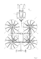
- FIG 3 shows the four-rotor swather 1 in a side view in the direction of travel F. with the rotors 3,3 'in the transport position.
- FIG. 4 shows the four-rotor rake 1 in a plan view of the ground 28 in Direction of travel F with rotated rotors 3,3 'in the transport position according to Fig. 3.
- the gyroscope 3, 3 ', 4, 4' folded up are simplified as contours shown.
Abstract
Description
Die Erfindung betrifft einen Kreiselschwader mit vier Rechkreiseln nach dem
gattungsbildenden Oberbegriff des Anspruchs 1.The invention relates to a rotary swather with four rakes after
Generic preamble of
In der Patentschrift DE 197 16 379 C1 ist ein Vierkreiselschwader nach dem
gattungsbildenden Oberbegriff des Anspruchs 1 dargestellt. Demzufolge ist jeder
Rechkreisel mit einem ihm zugeordneten um horizontale Klappachsen
schwenkbaren Ausleger mit dem Fahrgestell verbunden.In the patent DE 197 16 379 C1 is a four-rotor rake after
Generic preamble of
Aufgabe der Erfindung ist es, einen Vierkreiselschwader zu schaffen, der in seiner konstruktiven Ausbildung mit einfachen Mitteln kostengünstig gestaltet werden kann, welches seine Wirtschaftlichkeit gegenüber vergleichbaren Vierkreiselschwadern verbessert.The object of the invention is to provide a four-rotor rake which in his constructive training inexpensively designed with simple means can be compared to its economic viability Four-rotor rakes improved.
Gelöst wird diese Aufgabe mit den Merkmalen des kennzeichnenden Teils des
Anspruchs 1. Weitere Vorteile und Ausgestaltungen nach der Erfindung sind der
nachfolgenden Beschreibung, den Zeichnungen und den Ansprüchen 2 bis 11 zu
entnehmen. This task is solved with the characteristics of the characteristic part of the
Bezugszeichenliste
- 1 -
- Vierkreiselschwader
- 2 -
- Traktor
- 3,3' -
- innerer Rechkreisel
- 4,4' -
- äußerer Rechkreisel
- 5-
- Fahrgestell
- 6,6' -
- innerer Ausleger
- 7,7' -
- äußerer Ausleger
- 8-
- Kuppelglied
- 9-
- Hochachse
- 10 -
- Hauptträger
- 11 -
- Portalfahrwerk
- 12 -
- Laufräder
- 13,13' -
- Fahrwerk
- 14,14' -
- Klappachsen
- 15,15' -
- Horizontalgelenk
- 16,16' -
- Druckmittelzylinder
- 17,17' -
- Parallelogrammlenker
- 18,18' -
- Hochachse
- 19 -
- Schwenkgelenk
- 20 -
- Abstand
- 21,21' -
- Auslegerarm
- 22,22' -
- Auslegerarm
- 23,23' -
- Schwenkgelenk
- 24,24' -
- Hochachse
- 25,25' -
- Drehrichtung
- 26,26' -
- Endgabeln
- 27,27' -
- Querstrebe
- 28 -
- Erdboden
- F -
- Fahrtrichtung
- 1 -
- Four-rotor swather
- 2 -
- tractor
- 3.3 '-
- inner gyro
- 4.4 '-
- outer gyro
- 5-
- chassis
- 6.6 '-
- inner boom
- 7.7 '-
- outer boom
- 8th-
- Coupling element
- 9-
- Vertical axis
- 10 -
- Main beam
- 11 -
- Portal chassis
- 12 -
- Wheels
- 13.13 '-
- landing gear
- 14.14 '-
- Folding axles
- 15.15 '-
- Horizontal joint
- 16.16 '-
- Pressure cylinder
- 17.17 '-
- Parallelogram handlebar
- 18.18 '-
- Vertical axis
- 19 -
- Swivel joint
- 20 -
- distance
- 21.21 '-
- Cantilever arm
- 22.22 '-
- Cantilever arm
- 23.23 '-
- Swivel joint
- 24.24 '-
- Vertical axis
- 25.25 '-
- Direction of rotation
- 26.26 '-
- End forks
- 27.27 '-
- Cross strut
- 28 -
- ground
- F -
- Direction of travel
Fig. 1 zeigt einen gezogenen Vierkreiselschwader 1 in Arbeitsstellung in der
Draufsicht auf die Arbeitsebene nach der Erfindung, angehängt an einen Traktor
2 in Fahrtrichtung F. Der Vierkreiselschwader 1 besteht im wesentlichen aus
dem Fahrgestell 5, dem Kupplungsglied 8 zum Anschluß an die Unterlenker
eines Traktors 2, dem Portalfahrwerk 11 am hinteren Ende des Fahrgestells 5,
den inneren Auslegern 6,6', den äußeren Auslegern 7,7', den inneren
Rechkreiseln 3,3', den äußeren Rechkreiseln 4,4' und den Fahrwerken 13,13',
auf denen sich jeweils die inneren Rechkreisel 3,3',4,4' gegenüber dem Boden in
der Arbeitsstellung abstützen. Die Rechkreisel 3,3',4,4' sind in bekannte Weise
mit durch eine Kurvenbahn gesteuerten Zinkenarmen mit Rechzinken bestückt.Fig. 1 shows a trailed four-
Das Fahrgestell 5 besteht im wesentlichen aus dem Hauptträger 5,
beispielsweise ausgebildet als Hohlprofil, wobei der Hauptträger 10 an seinem
vorderen Ende mittels eines Schwenkgelenks 19 um die Hochachse 9
verschwenkbar mit dem Kupplungsglied 8 verbunden ist, und am hinteren Ende
mit dem Portalfahrwerk 11 starr verbunden ist.The
Ein Teil der Gewichtskräfte des Fahrgestells 5 wird somit von den Unterlenkern
des Traktors 2 und damit vom Traktor, und ein anderer Teil von den Laufrädern
12 des Portalfahrwerks 11, gegenüber dem Boden abgestützt.A part of the weight of the
Die inneren Ausleger 6,6' sind mittels Horizontalgelenken 15,15' um in
Fahrtrichtung F verlaufende Klappachsen 14,14' hochklappbar mit dem
Hauptträger 10 verbunden. Jeder der inneren Ausleger 6,6' besitzt zwei
Horizontalgelenke 15,15 bzw. 15',15', die im Abstand 20 zueinander angeordnet
sind. Jeder der inneren Ausleger besteht aus zwei Auslegerarmen 21,21';22,22',
wobei am freien Ende der Auslegerarme 21,22 jeweils der innere Rechkreisel
3,3' um ihre jeweilige Hochachse 18,18' dreh- und antreibbar gelagert sind. Die
Hochachsen 18,18' bilden gleichzeitig die Schwenkachsen für die
Schwenkgelenke 23,23' der äußeren Ausleger 7,7', an deren freien Enden die
äußeren Rechkreisel 4,4' um ihre jeweilige Hochachse 24,24' dreh- und
antreibbar gelagert sind.The
Die Schwenkgelenke 23,23' werden dabei überbrückt durch die
Druckmittelzylinder 16,16', so dass durch die Betätigung des
Druckmittelzylinders 16,16' durch Druckbeaufschlagung die äußeren Ausleger
7,7' um die Hochachsen 18,18' verschwenkt werden können. Dabei können die
Druckmittelzylinder 16,16' mittels entsperrbarer Zwillingsrückschlagventile so
angesteuert werden, dass ihre jeweiligen Kolbenstangen hydraulisch
eingespannt sind, so dass die Schwenkgelenke 23,23' festgesetzt, das heißt in
ihrer eingestellten Arbeits- oder Transportstellung überbrückt werden können.The swivel joints 23, 23 'are bridged by the
Desweiteren werden die Fahrwerke 13,13' der äußeren Rechkreisel 4,4' mittels
eines Parallelogrammlenkers 17,17' in ihrem Spurverhalten und damit in ihrer
Fahrtrichtung gesteuert.Furthermore, the
Die Drehrichtungen der Rechkreisel 25,25' sind seitenweise, d.h. links des
Hauptträgers bzw. rechts des Hauptträgers gegenläufig zueinander, so dass der
Vierkreiselschwader 1 einen Mittelschwad erzeugen kann.The directions of rotation of the
Fig. 2 zeigt den Vierkreiselschwader 1 in einer Zwischenstellung als
Ausgangsstellung zum Hochklappen der Rechkreisel 3,3',4,4'. Dabei wurde der
Vierkreiselschwader 1 aus seiner Arbeitsstellung durch Betätigung der
Druckmittelzylinder 16,16' in diese Zwischenstellung überführt, indem die
äußeren Rechkreisel 4,4' einschließlich der äußeren Ausleger 7.7' um die
Hochachsen 18,18' der Schwenkgelenke 23,23' soweit nach innen verschwenkt
wurden, dass die äußeren Ausleger 7,7' etwa parallel zum Hauptträger 10
ausgerichtet sind. Die freien Enden der Auslegerarme 21',22' sind gabelförmig
ausgebildet und dienen den äußeren Auslegern 7,7' gleichzeitig als
Endanschlag. Die Endgabeln 26,26' umfassen dabei den jeweiligen äußeren
Ausleger 7,7', der zweckmäßigerweise als Vierkanthohlprofil ausgebildet ist. Fig. 2 shows the four-
Dabei sind die Endgabeln 26,26' U-förmig derart ausgebildet, dass die jeweils
zur nach außen vom Hauptträger 10 abgewandten Seite offen sind, so dass die
äußeren Ausleger 7,7' horizontal in die offene Endgabel 26,26' einschwenken
können. Die Auslegerarme 21,21' bzw. 22,22' sind untereinander mittels einer
Querstrebe 27,27' verbunden, so dass die Auslegerarme 21,21';22,22' eine
stabile Einheit als innere Ausleger 6,6' bilden, so dass die inneren Ausleger 6,6'
von einem, aus Gründen der Übersichtlichkeit nicht dargestellten,
Druckmittelzylinder um die Klappachsen 14,14' in ihre Transportstellung
hochgeschwenkt werden können.The
Fig. 3 zeigt den Vierkreiselschwader 1 in einer Seitenansicht in Fahrtrichtung F
mit hochgeklappten Kreiseln 3,3' in Transportstellung.3 shows the four-
Fig. 4 zeigt den Vierkreiselschwader 1 in einer Draufsicht auf die Erdboden 28 in
Fahrtrichtung F mit hochgeklappten Kreiseln 3,3' in Transportstellung gemäß
Fig. 3. Dabei sind die hochgeklappten Kreisel 3,3';4,4' als Konturen vereinfacht
dargestellt.FIG. 4 shows the four-
Claims (11)
Applications Claiming Priority (2)
| Application Number | Priority Date | Filing Date | Title |
|---|---|---|---|
| DE19960662 | 1999-12-15 | ||
| DE1999160662 DE19960662A1 (en) | 1999-12-15 | 1999-12-15 | Haymaking machine, especially a four-rotor rake |
Publications (1)
| Publication Number | Publication Date |
|---|---|
| EP1108352A1 true EP1108352A1 (en) | 2001-06-20 |
Family
ID=7932861
Family Applications (1)
| Application Number | Title | Priority Date | Filing Date |
|---|---|---|---|
| EP00126907A Withdrawn EP1108352A1 (en) | 1999-12-15 | 2000-12-08 | Haymaking machine especially swather with four rotors |
Country Status (2)
| Country | Link |
|---|---|
| EP (1) | EP1108352A1 (en) |
| DE (1) | DE19960662A1 (en) |
Cited By (9)
| Publication number | Priority date | Publication date | Assignee | Title |
|---|---|---|---|---|
| EP1281307A1 (en) * | 2001-08-01 | 2003-02-05 | George Moate | Agricultural implement |
| NL1022564C2 (en) * | 2003-02-03 | 2004-08-04 | Lely Entpr Ag | Haymaking machine has connecting component with first outer end fixable to towing vehicle and has two crop processing components |
| EP1493325A1 (en) * | 2003-07-04 | 2005-01-05 | Maschinenfabrik Bernard Krone GmbH | Haymaking machine |
| EP1495667A1 (en) * | 2003-07-04 | 2005-01-12 | Maschinenfabrik Bernard Krone GmbH | Haymaking machine |
| FR2861538A1 (en) * | 2003-10-29 | 2005-05-06 | Kuhn Sa | AGRICULTURAL MACHINE FOR COMBINING ANDAIN AND ANDAINER PRODUCTS ON THE GROUND |
| EP1554922A1 (en) * | 2004-01-15 | 2005-07-20 | Claas Saulgau Gmbh | Rotary swather |
| EP2113164A3 (en) * | 2008-04-30 | 2010-01-20 | JF-Fabriken - J. Freudendahl A/S | Rotary rake |
| FR2937830A1 (en) * | 2008-11-06 | 2010-05-07 | Kuhn Sa | FENNING MACHINE, IN PARTICULAR FOR THE ETANAGE OF PLANTS |
| ITMI20110767A1 (en) * | 2011-05-06 | 2012-11-07 | Feraboli S P A | ROUND-SANDING AGRICULTURAL MACHINE, VARIABLE SET-UP. |
Citations (7)
| Publication number | Priority date | Publication date | Assignee | Title |
|---|---|---|---|---|
| US4056923A (en) * | 1975-02-04 | 1977-11-08 | Zweegers P | Agricultural implement |
| DE3418352A1 (en) * | 1984-05-17 | 1986-01-09 | Max 8951 Baisweil Hölzle | Appliance for raking together fodder, especially for front mounting on a tractor |
| DE29623121U1 (en) * | 1996-07-16 | 1997-12-18 | Claas Saulgau Gmbh | Rotary rakes |
| DE19716379C1 (en) | 1997-04-18 | 1998-06-18 | Krone Bernhard Gmbh Maschf | Agricultural harvester machine for standing crops |
| DE19736460A1 (en) * | 1997-08-21 | 1999-02-25 | Poettinger Ohg Alois | Rotary swather for gathering hay |
| EP0937383A1 (en) * | 1998-02-23 | 1999-08-25 | Maschinenfabrik Bernard Krone GmbH | Haymaking machine |
| WO2000062595A1 (en) * | 1999-03-09 | 2000-10-26 | Maasland N.V. | A haymaking machine |
Family Cites Families (1)
| Publication number | Priority date | Publication date | Assignee | Title |
|---|---|---|---|---|
| DE9010179U1 (en) * | 1990-07-04 | 1990-09-20 | H. Niemeyer Soehne Gmbh & Co Kg, 4446 Hoerstel, De |
-
1999
- 1999-12-15 DE DE1999160662 patent/DE19960662A1/en not_active Withdrawn
-
2000
- 2000-12-08 EP EP00126907A patent/EP1108352A1/en not_active Withdrawn
Patent Citations (7)
| Publication number | Priority date | Publication date | Assignee | Title |
|---|---|---|---|---|
| US4056923A (en) * | 1975-02-04 | 1977-11-08 | Zweegers P | Agricultural implement |
| DE3418352A1 (en) * | 1984-05-17 | 1986-01-09 | Max 8951 Baisweil Hölzle | Appliance for raking together fodder, especially for front mounting on a tractor |
| DE29623121U1 (en) * | 1996-07-16 | 1997-12-18 | Claas Saulgau Gmbh | Rotary rakes |
| DE19716379C1 (en) | 1997-04-18 | 1998-06-18 | Krone Bernhard Gmbh Maschf | Agricultural harvester machine for standing crops |
| DE19736460A1 (en) * | 1997-08-21 | 1999-02-25 | Poettinger Ohg Alois | Rotary swather for gathering hay |
| EP0937383A1 (en) * | 1998-02-23 | 1999-08-25 | Maschinenfabrik Bernard Krone GmbH | Haymaking machine |
| WO2000062595A1 (en) * | 1999-03-09 | 2000-10-26 | Maasland N.V. | A haymaking machine |
Cited By (15)
| Publication number | Priority date | Publication date | Assignee | Title |
|---|---|---|---|---|
| EP1281307A1 (en) * | 2001-08-01 | 2003-02-05 | George Moate | Agricultural implement |
| NL1022564C2 (en) * | 2003-02-03 | 2004-08-04 | Lely Entpr Ag | Haymaking machine has connecting component with first outer end fixable to towing vehicle and has two crop processing components |
| EP1493325A1 (en) * | 2003-07-04 | 2005-01-05 | Maschinenfabrik Bernard Krone GmbH | Haymaking machine |
| EP1495667A1 (en) * | 2003-07-04 | 2005-01-12 | Maschinenfabrik Bernard Krone GmbH | Haymaking machine |
| US7673439B2 (en) | 2003-10-29 | 2010-03-09 | Kuhn S.A. | Agricultural machine for swathing products lying on the ground |
| FR2861538A1 (en) * | 2003-10-29 | 2005-05-06 | Kuhn Sa | AGRICULTURAL MACHINE FOR COMBINING ANDAIN AND ANDAINER PRODUCTS ON THE GROUND |
| WO2005041638A1 (en) * | 2003-10-29 | 2005-05-12 | Kuhn S.A. | Agricultural machine for swathing products lying on the ground |
| CN100384316C (en) * | 2003-10-29 | 2008-04-30 | 库恩股份有限公司 | Agricultural machine for swathing products lying on the ground |
| AU2004285320B2 (en) * | 2003-10-29 | 2009-12-10 | Kuhn S.A. | Agricultural machine for swathing products lying on the ground |
| EP1554922A1 (en) * | 2004-01-15 | 2005-07-20 | Claas Saulgau Gmbh | Rotary swather |
| EP2113164A3 (en) * | 2008-04-30 | 2010-01-20 | JF-Fabriken - J. Freudendahl A/S | Rotary rake |
| FR2937830A1 (en) * | 2008-11-06 | 2010-05-07 | Kuhn Sa | FENNING MACHINE, IN PARTICULAR FOR THE ETANAGE OF PLANTS |
| EP2183956A1 (en) | 2008-11-06 | 2010-05-12 | Kuhn S.A. | Haymaking machine |
| ITMI20110767A1 (en) * | 2011-05-06 | 2012-11-07 | Feraboli S P A | ROUND-SANDING AGRICULTURAL MACHINE, VARIABLE SET-UP. |
| WO2012153243A1 (en) * | 2011-05-06 | 2012-11-15 | Feraboli S.P.A. | Rotary windrower with variable configuration |
Also Published As
| Publication number | Publication date |
|---|---|
| DE19960662A1 (en) | 2002-04-18 |
Similar Documents
| Publication | Publication Date | Title |
|---|---|---|
| EP2022316B1 (en) | Haymaking machine | |
| EP1949781B1 (en) | Haymaking machine | |
| DE2220114A1 (en) | HAYMAKING MACHINE | |
| DE4142000B4 (en) | Twin-rotor windrower | |
| DE19952555C2 (en) | Hay-making machine | |
| EP1108352A1 (en) | Haymaking machine especially swather with four rotors | |
| EP2022317B1 (en) | Hay making machine | |
| DE4021812C2 (en) | Haymaking machine | |
| DE202011107679U1 (en) | Hay-making machine | |
| DE102012108904A1 (en) | Device mounting device of a work vehicle | |
| EP0937382B1 (en) | Rotary tedder | |
| EP1618778B1 (en) | Rotary swather | |
| DE4142496C2 (en) | Haymaking machine | |
| EP1829444B1 (en) | Rotary swather | |
| DE3835367C2 (en) | Device for mowers for ground adaptation of the cutting units | |
| DE4201881A1 (en) | Rotary swather with rotary rakes following curved track - has changeable position of curved track through rotation about rotary axis of rake | |
| EP2394505B1 (en) | Haymaking machine | |
| DE102004051678A1 (en) | Gyro windrow for agricultural applications has further stepped rows arranged before the last stepped row | |
| DE10110096A1 (en) | Agricultural harvesting machine for hay has beams towed by tractor with tines on extendable rotating beams supported by pairs of wheels | |
| DE3801804A1 (en) | Haymaking machine | |
| EP0819373B1 (en) | Agricultural implement especially multiple rotor hay-turner | |
| AT413779B (en) | SCHWADVORRICHTUNG WITH TWO SWIMMING DRUM | |
| DE19736460A1 (en) | Rotary swather for gathering hay | |
| EP1527673A1 (en) | Rotary swather | |
| DE20018819U1 (en) | Rotary rakes with telescopic booms |
Legal Events
| Date | Code | Title | Description |
|---|---|---|---|
| PUAI | Public reference made under article 153(3) epc to a published international application that has entered the european phase |
Free format text: ORIGINAL CODE: 0009012 |
|
| AK | Designated contracting states |
Kind code of ref document: A1 Designated state(s): AT DE FR NL |
|
| AX | Request for extension of the european patent |
Free format text: AL;LT;LV;MK;RO;SI |
|
| 17P | Request for examination filed |
Effective date: 20010717 |
|
| AKX | Designation fees paid |
Free format text: AT DE FR NL |
|
| 17Q | First examination report despatched |
Effective date: 20030320 |
|
| STAA | Information on the status of an ep patent application or granted ep patent |
Free format text: STATUS: THE APPLICATION IS DEEMED TO BE WITHDRAWN |
|
| 18D | Application deemed to be withdrawn |
Effective date: 20030731 |