EP1107645B1 - Dispositif prefectionné de chauffage ohmique d'un fluide, installation de traitement d'un fluide incorporant un tel dispositif et procédé de traitement d'un fluide par chauffage ohmique. - Google Patents
Dispositif prefectionné de chauffage ohmique d'un fluide, installation de traitement d'un fluide incorporant un tel dispositif et procédé de traitement d'un fluide par chauffage ohmique. Download PDFInfo
- Publication number
- EP1107645B1 EP1107645B1 EP00403218A EP00403218A EP1107645B1 EP 1107645 B1 EP1107645 B1 EP 1107645B1 EP 00403218 A EP00403218 A EP 00403218A EP 00403218 A EP00403218 A EP 00403218A EP 1107645 B1 EP1107645 B1 EP 1107645B1
- Authority
- EP
- European Patent Office
- Prior art keywords
- fluid
- plates
- heater
- chamber
- outlet
- Prior art date
- Legal status (The legal status is an assumption and is not a legal conclusion. Google has not performed a legal analysis and makes no representation as to the accuracy of the status listed.)
- Expired - Lifetime
Links
- 239000012530 fluid Substances 0.000 title claims abstract description 186
- 238000010438 heat treatment Methods 0.000 title claims abstract description 46
- 238000000034 method Methods 0.000 title claims description 19
- 238000011282 treatment Methods 0.000 title claims description 6
- 238000009434 installation Methods 0.000 title description 25
- 230000000694 effects Effects 0.000 claims abstract description 8
- 125000006850 spacer group Chemical group 0.000 claims description 25
- 238000001816 cooling Methods 0.000 claims description 10
- 239000012809 cooling fluid Substances 0.000 claims 2
- 230000005611 electricity Effects 0.000 claims 2
- 230000004087 circulation Effects 0.000 description 13
- 239000003507 refrigerant Substances 0.000 description 10
- 230000008878 coupling Effects 0.000 description 5
- 238000010168 coupling process Methods 0.000 description 5
- 238000005859 coupling reaction Methods 0.000 description 5
- 230000000630 rising effect Effects 0.000 description 4
- 239000004696 Poly ether ether ketone Substances 0.000 description 2
- 239000011810 insulating material Substances 0.000 description 2
- 230000010354 integration Effects 0.000 description 2
- 239000008267 milk Substances 0.000 description 2
- 210000004080 milk Anatomy 0.000 description 2
- 235000013336 milk Nutrition 0.000 description 2
- 229920002530 polyetherether ketone Polymers 0.000 description 2
- 238000003825 pressing Methods 0.000 description 2
- 238000003466 welding Methods 0.000 description 2
- BYHQTRFJOGIQAO-GOSISDBHSA-N 3-(4-bromophenyl)-8-[(2R)-2-hydroxypropyl]-1-[(3-methoxyphenyl)methyl]-1,3,8-triazaspiro[4.5]decan-2-one Chemical compound C[C@H](CN1CCC2(CC1)CN(C(=O)N2CC3=CC(=CC=C3)OC)C4=CC=C(C=C4)Br)O BYHQTRFJOGIQAO-GOSISDBHSA-N 0.000 description 1
- JUPQTSLXMOCDHR-UHFFFAOYSA-N benzene-1,4-diol;bis(4-fluorophenyl)methanone Chemical compound OC1=CC=C(O)C=C1.C1=CC(F)=CC=C1C(=O)C1=CC=C(F)C=C1 JUPQTSLXMOCDHR-UHFFFAOYSA-N 0.000 description 1
- 238000004140 cleaning Methods 0.000 description 1
- 239000004020 conductor Substances 0.000 description 1
- 238000010586 diagram Methods 0.000 description 1
- 238000009826 distribution Methods 0.000 description 1
- 230000004907 flux Effects 0.000 description 1
- 235000013305 food Nutrition 0.000 description 1
- 238000003754 machining Methods 0.000 description 1
- 239000000463 material Substances 0.000 description 1
- 239000002184 metal Substances 0.000 description 1
- 238000000465 moulding Methods 0.000 description 1
- 229920000642 polymer Polymers 0.000 description 1
- 238000007789 sealing Methods 0.000 description 1
Images


Classifications
-
- H—ELECTRICITY
- H05—ELECTRIC TECHNIQUES NOT OTHERWISE PROVIDED FOR
- H05B—ELECTRIC HEATING; ELECTRIC LIGHT SOURCES NOT OTHERWISE PROVIDED FOR; CIRCUIT ARRANGEMENTS FOR ELECTRIC LIGHT SOURCES, IN GENERAL
- H05B3/00—Ohmic-resistance heating
- H05B3/60—Heating arrangements wherein the heating current flows through granular powdered or fluid material, e.g. for salt-bath furnace, electrolytic heating
Definitions
- the invention relates to the field of heat treatment of a fluid, and in particular heat treatments comprising at least one ohmic heating step.
- the invention relates more particularly to agro-food fluids, and especially those to be pasteurized or sterilized, for example.
- Ohmic heating is a well known technique of Joule volume heating. It consists in introducing an electric current in an interrupted electrical circuit at conductive plates by circulating an electrically conductive fluid between these plates. The fluid has a certain electrical resistance, it produces heat by the Joule effect, and therefore "self-heating".
- the patent document FR 94 08108 discloses an ohmic heating device comprising a tubular central channel at both ends of which planar electrodes are placed, pierced to allow the introduction of a fluid into the tube and its collection. These two electrodes are both perpendicular to the channel and the general flow direction of the fluid.
- the purpose of the invention is to provide a solution that is different from those known.
- an ohmic heating device which comprises at least one heating chamber delimited by walls, among which two are constituted by conductive plates, forming electrodes, substantially parallel to each other and spaced apart from each other by a selected distance.
- This chamber further comprises at least one inlet for introducing the fluid to be heated near a first end of the plates and at least one outlet placed near a second end of these plates, opposite the first end, and to collect the fluid after it has circulated between the plates, substantially parallel thereto.
- Means are also provided for supplying the plates with electric current, so that the fluid heats up in the chamber, by ohmic effect, during its circulation parallel to the plates.
- each chamber of the device comprises at least one spacer which defines the spacing between plates and comprises a recessed central part allowing the circulation of the fluid and having two lateral faces against which are placed the plates and which are provided with openings for allowing surface contact between the fluid and the plates.
- the spacer comprises, on either side of the central portion, respectively a first end portion in which is formed the fluid inlet inlet communicating with the central portion. recess and a second end portion in which is formed the fluid collection outlet communicating with the recessed central portion.
- the device may comprise one or more chambers juxtaposed to each other, in a sealed manner.
- the chambers are juxtaposed so that the exit of a chamber feeds the entrance of the chamber which follows it, while the entrance of this chamber is fed by the exit from the room that precedes it.
- the device can thus be flexible.
- the chambers are juxtaposed to each other, sealing, so that their respective inputs communicate with each other and that their respective outputs communicate with each other.
- the device comprises a first multiplicity of chambers and at least a second multiplicity of chambers, the output of one of the first and second multiplicities feeding the input of the other of the first and second multiplicities. All combinations of these two embodiments can be envisaged.
- Each chamber may comprise one or two juxtaposed spacers, or even more, especially so as to vary the spacing between the electrodes.
- the invention also relates to a fluid treatment installation which comprises the ohmic heating device presented above. More specifically, this installation comprises a device for heating a first fluid, coupled to a first heat exchanger comprising a first circuit where the first heated fluid flows from the device, and a second circuit where a second fluid circulates, the first and second wherein the first and second fluids exchange calories to lower the temperature of the first fluid and increase that of the second fluid of respective selected values.
- the first fluid is the heated fluid delivered at the outlet of the device, while the second fluid is a refrigerant.
- the output of the device always supplies the input of the first circuit of the first heat exchanger, but the output of the second circuit of this exchanger supplies the input of this same device.
- the first fluid is the fluid heated by the device, while the second fluid is the fluid to be heated by the device.
- the first heat exchanger thus simultaneously ensures the pre-heating of the fluid and the pre-cooling of the same fluid after heating.
- the first heat exchanger is preferably housed between a second heat exchanger and the device.
- the second heat exchanger comprises a third circuit where the first precooled fluid, delivered by the output of the first circuit, and a fourth circuit circulating a third refrigerant circulates, the third and fourth circuits being placed relative to each other. the other so that the first and third fluids exchange calories to lower the temperature of the first pre-cooled fluid by a selected value.
- each heat exchanger is of the stacked plate type.
- the successive plates define two by two fluid circulation chambers, and the successive chambers define portions of two different circuits to allow the exchange of calories between the fluids of these two circuits.
- the first and second heat exchangers may constitute a single general heat exchanger.
- the general exchanger and the device can be assembled in series by forming a monobloc structure by means of securing means, such as tie rods coupled to nuts.
- the device and the exchanger or exchangers can be physically separated, their coupling then being obtained by reported conduits.
- the invention also relates to a method of treating electrically conductive fluid by ohmic heating which comprises the steps indicated below.
- one (or more) heating chamber which comprises (include) two walls constituted by conductive plates forming electrodes, substantially parallel to each other and spaced apart from one another. chosen distance.
- the plates are fed with electric current.
- the fluid to be heated is introduced near a first end of the plates, then the fluid is circulated between the plates, substantially parallel thereto, so that it warms up inside the chamber. chamber, ohmic effect, and finally the heated fluid is collected near a second end of the plates, opposite the first end.
- a fourth step may be provided to lower the temperature of the first fluid by a value chosen by exchanging calories with a second fluid.
- the first fluid is the heated fluid delivered from the outlet of the (or) heating chamber (s), while the second fluid is a refrigerant.
- the first fluid is the heated fluid delivered by the heating chamber (s), while the second fluid is the fluid that must be heated by this (or these) chamber (s) heating.
- a pre-heating of the fluid and a pre-cooling of this fluid are carried out simultaneously after it has been heated.
- the method may comprise, after the fourth step, a fifth step for lowering by a selected value the temperature of the first pre-cooled fluid by heat exchange with a third refrigerant.
- This device 1 is, in the illustrated example, composed of five heating chambers juxtaposed to each other and communicating with each other.
- This device is therefore multichamber type, but it could have only one room.
- the number of chambers of the device according to the invention may vary according to the needs.
- a chamber 2 is delimited by two plates 3, 4 made of a conductive material, preferably metal, and a spacer 5 for adjusting the spacing between the two conductive plates 3 and 4. These plates are more preferably still of type DSA ("Dimension Stable Anode"). Such electrodes are described, in particular, in the European patent application 99 400 623.7.
- the spacer 5 is a three-dimensional element comprising a central portion 6, hollowed out, framed by two end portions 7 and 8 in which respectively a fluid intake inlet 9 is formed and a fluid collection outlet 10, which each communicate with the recessed central portion 6.
- the spacer 5 is made of an insulating material, for example a polymer, and more preferably PEEK (acronym for PolyEtherEtherKetone). But many other insulating materials can be considered.
- PEEK cronym for PolyEtherEtherKetone
- the embodiment of these spacers depends on the material used: machining and / or welding and / or molding.
- the intake inlet 9 and the collection outlet 10 are substantially L-shaped.
- the conductive plates 3 and 4 preferably have dimensions substantially equal to the dimensions of the lateral faces 11 of the 5. Accordingly, to allow the introduction of the fluid to be heated in the chamber 6, as the evacuation out of this chamber 6 of the collected and heated fluid, each conductive plate 3, 4 has an opening (or light) 12 at one of its two ends.
- Each conductive plate constitutes an electrode intended to be supplied with electric current by a circuit adapted for this purpose, not shown, or grounded (as is the case, in this example, end plates 3-E and 4-S).
- This power supply can be performed, for example at the side lug 13 that includes each plate 3, 4.
- the fluid which circulates substantially parallel to the plates, between the intake inlet 9 and the collection outlet 10 establishes a "connection" between the two conductive plates, so that said fluid releases heat from the fact that of its resistivity.
- the general power supply of the different conductive plates is carried out in a "triangle" type mode in which the end plates 3-E and 4-S are respectively placed at ground while the intermediate plates 3 and 4 are placed at selected potentials, for example 50 or 100 volts.
- This power supply mode is currently preferred. Indeed, in this mode of supply, the fluid inlet and fluid collection chambers which respectively include the plates 3-E and 4-S to ground, are not used to heat the fluid, but to "break »Possible leakage of current. In a variant, it is also possible to ground the two plates 4 and 3 which delimit the first and last chambers of the device with the two end plates 3-E and 4-S, respectively. These first and last chambers therefore act as insulating chambers. But it could be otherwise.
- the power of the device can be, for example, of the order of 6 kW three-phase for a flow rate of 300 l / h, or 120 kW for a flow rate of 6000 l / h.
- each conductive plate 3, 4 is used simultaneously by two successive chambers 6, so that the opening 12 that it comprises one of its two ends serves both as an admission opening and as a collection opening.
- the spacer always comprises a heating chamber 6 fed by an intake inlet 9 and feeding a collection outlet 10.
- the parts of the intake inlet 9 and the collection outlet 10 which open into the recessed portion of the chamber 6, are made in the form of "divergent" elements, which improves the distribution of the fluid inside the chamber and its collection output from this room.
- each spacer has a diverging element 14, 15.
- the flow that enters through the intake inlet 9 is subdivided into two substreams.
- the flows communicate with each other inside the heating chamber 6, so that the electric current can flow between the two conductive plates 3 and 4.
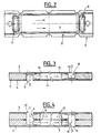
- FIG. 5 shows an ohmic heating device assembled by means of securing means such as tie rods 29 at the ends of which are screwed nuts 30.
- the assembly of the plates and spacers is therefore carried out by pressure .
- the device comprises a fluid inlet inlet 34 at the first chamber 2 (which includes the plate 3-E), and a fluid collection outlet 20 heated at the last chamber 2 (which comprises the plate 4 -S).
- the circulation of the fluid inside the device can be either completely alternating (rising / falling / rising / falling ...), which corresponds to a circulation "in series” as indicated above, or partially alternating (rising and falling down or descending then rising), as shown in Figure 6, which corresponds to a circulation of "parallel / series" type.
- the device comprises a first part which feeds a second part.
- the first part comprises three chambers supplied with fluid from above, in parallel, the fluid having circulated in each chamber being collected at the bottom.
- the second part comprises three chambers supplied with fluid from the first part, from below, in parallel, the fluid having circulated in each chamber being collected at the top and feeding the outlet 20 of the device.
- FIGS. 7A to 7D describe an embodiment of a fluid treatment installation according to the invention.
- Such an invention is particularly advantageous in applications where it is first necessary to heat a fluid at a given temperature, for example 140 ° C, in order to sterilize or pasteurize, and secondly to lower its temperature to a second value, lower than the first, for example in order to condition it.
- Coupling is here understood to mean an integration in which the device and the heat exchanger (s) form a monoblock-type assembly (as illustrated in FIG. 7), or an association in which the device and the heat exchanger (s) are connected to each other by conduits (as shown in Figures 9 and 10).
- FIGS. 7A to 7D illustrate an exemplary embodiment of an installation according to the invention in which the device 1 is coupled, in line, to a general heat exchanger 17 with "two stages" (or two parts).
- the first stage 16 (or first part, or first exchanger) is used, both to preheat the fluid that must be heated to the first temperature by the device 1, and to pre-cool, at a so-called “intermediate” temperature, the fluid that has just been heated by the device 1.
- the second portion 18 is used to cool the fluid that has just been pre-cooled by the first portion 16 of the heat exchanger 17 at a second temperature.
- the first part 16 of the general heat exchanger 17 has on the side of the device 1, preferably an inlet 19 supplied with fluid heated by the outlet 20 of the device 1.
- This inlet 19 supplies a first circuit 21 (see Figure 8) which feeds cooled fluid at the outlet of the first portion 16, the second portion 18 to which we will return later.
- the first part 16 has another inlet 22, preferably placed opposite the inlet 19, that is to say on the side of the second part 18 of the exchanger 17.
- This inlet 22 supplies a second circuit 23 which preferably has a circulation alternating with that of the heated fluid which circulates inside the first circuit.
- the first 21 and second 23 circuits are arranged so as to allow an exchange of calories between the heated fluid and the cold fluid to be preheated.
- the first part 16 of the heat exchanger 17 consists of stacked plates 24 which delimit, in pairs, chambers in which the two types of fluid circulate (heated and heated). ).
- the stacked plates are corrugated type.
- corrugated plates 24 is well known to those skilled in the art. It is therefore unnecessary to describe them in detail. What can be said is that the heated fluid as it circulates inside the first circuit 21, from the inlet 19 to the outlet 43 which feeds the second part 18, loses calories in favor of the fluid to be heated flowing in the second circuit 23, from the inlet 22 to the device 1.
- the second portion 18 of the heat exchanger 17 is formed in the same manner as the first part 16. It therefore comprises a series of stacked plates 24 which define two by two heat exchange chambers. More specifically, the pre-cooled fluid circulates inside a third circuit 32 which terminates at an outlet 26. To cool this precooled fluid, there is provided a fourth circuit 33 also constituted by the stacked plates corrugated 24. This fourth circuit 33 is supplied with refrigerant by an inlet 27 placed at an end face of the exchanger 17 opposite the device 1, and opens into an outlet 28 which is, in the illustrated example in FIG. 5, also placed at this face opposite the device 1.
- the pre-cooled fluid circulating in the third circuit 32 from the outlet 43 of the first part 16 to the outlet 27, loses calories in favor of the refrigerant flowing in the fourth circuit 33, between entrance 27 and exit 28.
- the device 1 has transverse dimensions substantially identical to those of the general heat exchanger 17.
- the transverse dimensions of the stacked, corrugated plates, 24, spacers 5 and conductive plates 3 and 4 are substantially identical. Only the cheeks that define the end plates of the heat exchanger and / or the device, will possibly have slightly different dimensions, if necessary, for example for fixing or resistance issues.
- the device will preferably comprise, on the one hand, at each of its ends and, on the other hand, at the interface between the parts of the heat exchanger and between the heat exchanger and the device, collector boxes 31 made, preferably in the form of specific curved plates, optionally reinforced providing volumes of fluid circulation more important.
- the installation according to the invention can be declined in many variants, especially at the locations of the inputs and outputs.
- a particularly interesting variant is to use a heat exchanger that has only one part. Two cases may be considered
- the fluid flowing in the second circuit 23 is the fluid to be heated. This fluid is therefore preheated by the fluid that has just been heated by the device 1, which circulates in the first circuit 21 and is itself pre-cooled by the fluid flowing in the second circuit 23.
- the fluid flowing in the second circuit 23 is a refrigerant, and the fluid to be heated directly feeds the inlet 34 of the device 1.
- the fluid to be heated is not preheated, and that the heated fluid is not pre-cooled, it is indeed cooled by the refrigerant.
- the device 1 is coupled (associated) by two conduits 40, 41 to a general heat exchanger 17 with two stages 16 and 18.
- the output 42 of the second circuit 23 of the first part 16 of the exchanger 17 feeds preheated fluid via the conduit 40, the inlet 34 of the device 1, while the outlet 20 of the device supplies heated fluid, via the conduit 41, the inlet 19 of the first circuit 21 of the first part 16 of the exchanger 17.
- the device 1 is therefore a mechanically independent element of the exchanger 17 with which it cooperates via the fluid.
- the general exchanger is thus assembled separately from the device 1, for example using tie rods 29 and nuts 31.
- the device 1 is coupled (associated) by two ducts 40, 41 to a first heat exchanger 16.
- the outlet 42 of the second circuit 23 of the first heat exchanger 16 supplies pre-fluid -Heated via the conduit 40, the inlet 34 of the device 1, while the outlet 20 of the device supplies heated fluid, via the conduit 41, the inlet 19 of the first circuit 21 of the first heat exchanger 18.
- the first heat exchanger 16 is coupled (associated) via a conduit 45 to a second heat exchanger 18 for cooling the pre-cooled fluid.
- the output 43 of the first circuit 21 of the first heat exchanger 16 feeds pre-cooled fluid, via the conduit 45, the inlet 44 of the third circuit 32 of the second heat exchanger 18.
- the cooled fluid opens from the third circuit 32 by the exit 28.
- the device 1 is therefore an element of the mechanically independent installation of both the first 16 and second 18 heat exchangers with which it cooperates through the fluid to be heated.
- the two heat exchangers are thus assembled separately from one another, for example by means of tie-rods 29 and nuts 31.
- the dimensions of the two heat exchangers are necessarily identical. It may indeed be advantageous that, for example, the second exchanger is larger than the first.
- the invention also relates to a method of treating fluid by ohmic heating. This process is characterized by the steps given below.
- each chamber therefore comprises two walls constituted by conductive plates substantially parallel to each other and spaced apart from each other. a chosen distance.
- two successive heating chambers share the same conductive plate.
- the conductive plates are supplied with electric current.
- the fluid to be heated is introduced near a first end of the conductive plates, then this fluid is circulated between the plates, substantially parallel thereto, so that it can be heated to the interior of the rooms, by ohmic effect. Finally, the fluid thus heated is collected near a second end of the plates, opposite the first end.
- the fluid is fully warmed once it reaches the outlet of the very last chamber.
- the method may comprise a fourth step, coming after the third step, and intended to lower the temperature of the first fluid to a chosen value, by exchanging calories with a second fluid.
- This second fluid may be either a refrigerant or the fluid to be heated, itself, and in this case the fluid to be heated is preheated by the first fluid.
Landscapes
- Food Preservation Except Freezing, Refrigeration, And Drying (AREA)
- Heat-Exchange Devices With Radiators And Conduit Assemblies (AREA)
- Control Of Resistance Heating (AREA)
- Dairy Products (AREA)
- Apparatus For Disinfection Or Sterilisation (AREA)
- Liquid Developers In Electrophotography (AREA)
- Manufacture And Refinement Of Metals (AREA)
- External Artificial Organs (AREA)
- Physical Or Chemical Processes And Apparatus (AREA)
- Wire Bonding (AREA)
- Resistance Heating (AREA)
- Separation Using Semi-Permeable Membranes (AREA)
Applications Claiming Priority (2)
| Application Number | Priority Date | Filing Date | Title |
|---|---|---|---|
| FR9915215A FR2802052B1 (fr) | 1999-12-02 | 1999-12-02 | Dispositif perfectionne de chauffage ohmique d'un fluide, installation de traitement d'un fluide incorporant un tel dispositif et procede de traitement d'un fluide par chauffage ohmique |
| FR9915215 | 1999-12-02 |
Publications (2)
| Publication Number | Publication Date |
|---|---|
| EP1107645A1 EP1107645A1 (fr) | 2001-06-13 |
| EP1107645B1 true EP1107645B1 (fr) | 2007-05-09 |
Family
ID=9552814
Family Applications (1)
| Application Number | Title | Priority Date | Filing Date |
|---|---|---|---|
| EP00403218A Expired - Lifetime EP1107645B1 (fr) | 1999-12-02 | 2000-11-17 | Dispositif prefectionné de chauffage ohmique d'un fluide, installation de traitement d'un fluide incorporant un tel dispositif et procédé de traitement d'un fluide par chauffage ohmique. |
Country Status (9)
| Country | Link |
|---|---|
| US (1) | US6421501B2 (da) |
| EP (1) | EP1107645B1 (da) |
| JP (1) | JP3642731B2 (da) |
| AT (1) | ATE362298T1 (da) |
| AU (1) | AU1868601A (da) |
| DE (1) | DE60034757T2 (da) |
| DK (1) | DK1107645T3 (da) |
| FR (1) | FR2802052B1 (da) |
| WO (1) | WO2001041509A1 (da) |
Families Citing this family (11)
| Publication number | Priority date | Publication date | Assignee | Title |
|---|---|---|---|---|
| SE516844C3 (sv) * | 2000-07-07 | 2002-04-17 | Alfa Laval Ab | Plattvärme/plattvärmeväxlare med elektriskt uppvärmbara skikt i dubbelväggiga plattelement |
| FR2823995B1 (fr) * | 2001-04-25 | 2008-06-06 | Alfa Laval Vicarb | Dispositif perfectionne d'echange et/ou de reaction entre fluides |
| US7171111B2 (en) * | 2002-07-03 | 2007-01-30 | Sheldon Carlton W | Method of heating water with rod shaped electrodes in a two-dimensional matrix |
| US20060291822A1 (en) * | 2002-12-24 | 2006-12-28 | Sheldon Carlton W | Sheldon electro-matrix core |
| FR2874306B1 (fr) * | 2004-08-19 | 2008-01-11 | Bel Fromageries | Procede d'assainissement d'un produit fromager visqueux |
| US20130075060A1 (en) * | 2010-01-11 | 2013-03-28 | Ge Healthcare Bio-Sciences Ab | Aseptic connection of heat exchanger units |
| US20140072288A1 (en) | 2011-05-12 | 2014-03-13 | Nxstage Medical, Inc. | Fluid heating apparatuses, systems, and methods |
| AU2013235914B2 (en) * | 2012-03-20 | 2017-01-12 | Stichting Wageningen Research | Process for fast and homogeneously heating a liquid product and apparatus for such process |
| PL2667684T3 (pl) * | 2012-05-23 | 2018-02-28 | Fruit Tech Natural, S.A. | Urządzenie i sposób nagrzewania oporowego cieczy z cząstkami |
| WO2015089408A1 (en) * | 2013-12-12 | 2015-06-18 | Massachusetts Institute Of Technology | Tunable nucleate boiling using electric fields and ionic surfactants |
| EP2957848A1 (en) | 2014-06-17 | 2015-12-23 | Alfa Laval Corporate AB | A heater and a heat exchanger installation |
Family Cites Families (15)
| Publication number | Priority date | Publication date | Assignee | Title |
|---|---|---|---|---|
| US535267A (en) * | 1895-03-05 | Electrolytic conduit for beer or other liquids | ||
| US2188625A (en) * | 1936-12-24 | 1940-01-30 | Dufour Rene Alphonse | Device for the heating of flowing liquids such as rubber latex |
| US2314966A (en) * | 1937-03-29 | 1943-03-30 | Astle William | Plate heat exchanger |
| US2392021A (en) * | 1940-10-05 | 1946-01-01 | Cherry Burrell Corp | Heat exchange apparatus |
| US2659580A (en) * | 1950-04-19 | 1953-11-17 | Separator Ab | Plate heat exchanger |
| FR1143495A (fr) * | 1952-07-15 | 1957-10-01 | Four électrique à bain de sel | |
| US2937856A (en) * | 1956-01-26 | 1960-05-24 | Kusel Dairy Equipment Co | Plate heat exchanger |
| NL215577A (da) * | 1956-03-21 | |||
| US3299252A (en) * | 1964-08-10 | 1967-01-17 | John E Meek | Electric fluid heating device |
| US3414436A (en) * | 1966-09-16 | 1968-12-03 | American Factors Ass Ltd | Resistance massecuite heater |
| US3469012A (en) * | 1967-11-20 | 1969-09-23 | Eastman Kodak Co | Process for supplying precisely controlled supplemental heating to polymer melts |
| US4542034A (en) * | 1982-08-10 | 1985-09-17 | Alfa-Laval Ab | Method for heat treatment of milk and the like |
| US5290583A (en) * | 1992-04-02 | 1994-03-01 | David Reznik | Method of electroheating liquid egg and product thereof |
| FR2722053B1 (fr) * | 1994-06-30 | 1996-09-20 | Electricite De France | Dispositif et procede de chauffage d'un liquide ionique en ecoulement |
| IL121527A0 (en) * | 1997-08-12 | 1998-02-08 | U E T Ltd | Heating systems based on alternating-current electrodes |
-
1999
- 1999-12-02 FR FR9915215A patent/FR2802052B1/fr not_active Expired - Fee Related
-
2000
- 2000-11-17 DK DK00403218T patent/DK1107645T3/da active
- 2000-11-17 WO PCT/FR2000/003208 patent/WO2001041509A1/fr not_active Ceased
- 2000-11-17 AU AU18686/01A patent/AU1868601A/en not_active Abandoned
- 2000-11-17 AT AT00403218T patent/ATE362298T1/de not_active IP Right Cessation
- 2000-11-17 EP EP00403218A patent/EP1107645B1/fr not_active Expired - Lifetime
- 2000-11-17 DE DE60034757T patent/DE60034757T2/de not_active Expired - Lifetime
- 2000-12-01 JP JP2000366577A patent/JP3642731B2/ja not_active Expired - Fee Related
- 2000-12-01 US US09/726,495 patent/US6421501B2/en not_active Expired - Lifetime
Non-Patent Citations (1)
| Title |
|---|
| None * |
Also Published As
| Publication number | Publication date |
|---|---|
| DE60034757D1 (de) | 2007-06-21 |
| US6421501B2 (en) | 2002-07-16 |
| EP1107645A1 (fr) | 2001-06-13 |
| JP3642731B2 (ja) | 2005-04-27 |
| ATE362298T1 (de) | 2007-06-15 |
| DK1107645T3 (da) | 2007-09-24 |
| AU1868601A (en) | 2001-06-12 |
| FR2802052A1 (fr) | 2001-06-08 |
| DE60034757T2 (de) | 2008-01-17 |
| JP2001211825A (ja) | 2001-08-07 |
| FR2802052B1 (fr) | 2002-02-08 |
| US20010021308A1 (en) | 2001-09-13 |
| WO2001041509A1 (fr) | 2001-06-07 |
Similar Documents
| Publication | Publication Date | Title |
|---|---|---|
| EP1107645B1 (fr) | Dispositif prefectionné de chauffage ohmique d'un fluide, installation de traitement d'un fluide incorporant un tel dispositif et procédé de traitement d'un fluide par chauffage ohmique. | |
| EP2185046B1 (fr) | Chaudiere pour machine de preparation de boissons chaudes | |
| EP0964460B1 (fr) | Batterie monobloc comportant un dispositif d'échange thermique par circulation d'un fluide | |
| FR2720860A1 (fr) | Batterie fonctionnant à température élevée. | |
| EP2299882B1 (fr) | Chaudiere pour machine de preparation de boissons chaudes | |
| EP2931093B1 (fr) | Chaudière pour machine de préparation de boisson | |
| FR2815113A1 (fr) | Echangeur de chaleur en serpentin | |
| WO1995014893A1 (fr) | Chaudiere electrique pour liquide caloporteur en circulation dans un circuit ouvert ou ferme | |
| FR2745984A1 (fr) | Unite et installation de moulage et de traitement thermique de produits alimentaires | |
| FR2980260A1 (fr) | Evaporateur multi-nappes pour circuit de climatisation de vehicule automobile | |
| FR2901869A1 (fr) | Echangeur de chaleur, en particulier pour un systeme de chauffage ou de climatisation d'un vehicule automobile | |
| EP0690660B1 (fr) | Dispositif et procédé de chauffage d'un liquide ionique en écoulement | |
| WO2006000702A1 (fr) | Dispositif de chauffage d'un four a circulation d'air | |
| WO2005116436A1 (fr) | Echangeur de chaleur a plaques | |
| EP0597748B1 (fr) | Générateur de vapeur instantané | |
| FR3077459A1 (fr) | Unite de chauffe, radiateur de chauffage et boitier de climatisation, notamment de vehicule automobile | |
| EP1052469B1 (fr) | Module d'échange thermique | |
| EP0975919A1 (fr) | Corps de chauffe pour une chaudiere au fioul ou au gaz et modules pour la realisation d'un tel corps de chauffe | |
| EP1558887A2 (fr) | Echangeur de chaleur a passes multiples, en particulier pour vehicule automobile | |
| FR2953166A1 (fr) | Vehicule automobile comportant un moteur electrique alimente par une batterie et des moyens de refroidissement de la batterie. | |
| FR2588071A1 (fr) | Echangeur de chaleur avec tubes en matiere plastique | |
| WO2025219031A1 (fr) | Chauffe-eau électrique pour véhicule | |
| FR2482713A1 (fr) | Glacons et procede et dispositif de fabrication de glacons | |
| FR3149460A3 (fr) | Module de chauffage de véhicule et chauffage a thermistance associé pour véhicule | |
| FR2546489A1 (fr) | Recipient chauffant notamment pour flux de soudage |
Legal Events
| Date | Code | Title | Description |
|---|---|---|---|
| PUAI | Public reference made under article 153(3) epc to a published international application that has entered the european phase |
Free format text: ORIGINAL CODE: 0009012 |
|
| AK | Designated contracting states |
Kind code of ref document: A1 Designated state(s): AT BE CH CY DE DK ES FI FR GB GR IE IT LI LU MC NL PT SE TR |
|
| AX | Request for extension of the european patent |
Free format text: AL;LT;LV;MK;RO;SI |
|
| 17P | Request for examination filed |
Effective date: 20011207 |
|
| AKX | Designation fees paid |
Free format text: AT BE CH CY DE DK ES FI FR GB GR IE IT LI LU MC NL PT SE TR |
|
| RAP1 | Party data changed (applicant data changed or rights of an application transferred) |
Owner name: ELECTRICITE DE FRANCE, SOCIETE ANONYME Owner name: ALFA LAVAL VICARB |
|
| GRAP | Despatch of communication of intention to grant a patent |
Free format text: ORIGINAL CODE: EPIDOSNIGR1 |
|
| GRAS | Grant fee paid |
Free format text: ORIGINAL CODE: EPIDOSNIGR3 |
|
| GRAA | (expected) grant |
Free format text: ORIGINAL CODE: 0009210 |
|
| AK | Designated contracting states |
Kind code of ref document: B1 Designated state(s): AT BE CH CY DE DK ES FI FR GB GR IE IT LI LU MC NL PT SE TR |
|
| REG | Reference to a national code |
Ref country code: GB Ref legal event code: FG4D Free format text: NOT ENGLISH |
|
| REG | Reference to a national code |
Ref country code: CH Ref legal event code: EP |
|
| REG | Reference to a national code |
Ref country code: IE Ref legal event code: FG4D Free format text: LANGUAGE OF EP DOCUMENT: FRENCH |
|
| REF | Corresponds to: |
Ref document number: 60034757 Country of ref document: DE Date of ref document: 20070621 Kind code of ref document: P |
|
| PG25 | Lapsed in a contracting state [announced via postgrant information from national office to epo] |
Ref country code: ES Free format text: LAPSE BECAUSE OF FAILURE TO SUBMIT A TRANSLATION OF THE DESCRIPTION OR TO PAY THE FEE WITHIN THE PRESCRIBED TIME-LIMIT Effective date: 20070820 |
|
| REG | Reference to a national code |
Ref country code: SE Ref legal event code: TRGR |
|
| GBT | Gb: translation of ep patent filed (gb section 77(6)(a)/1977) |
Effective date: 20070813 |
|
| PG25 | Lapsed in a contracting state [announced via postgrant information from national office to epo] |
Ref country code: AT Free format text: LAPSE BECAUSE OF FAILURE TO SUBMIT A TRANSLATION OF THE DESCRIPTION OR TO PAY THE FEE WITHIN THE PRESCRIBED TIME-LIMIT Effective date: 20070509 |
|
| REG | Reference to a national code |
Ref country code: IE Ref legal event code: FD4D |
|
| PG25 | Lapsed in a contracting state [announced via postgrant information from national office to epo] |
Ref country code: PT Free format text: LAPSE BECAUSE OF FAILURE TO SUBMIT A TRANSLATION OF THE DESCRIPTION OR TO PAY THE FEE WITHIN THE PRESCRIBED TIME-LIMIT Effective date: 20071009 Ref country code: IE Free format text: LAPSE BECAUSE OF FAILURE TO SUBMIT A TRANSLATION OF THE DESCRIPTION OR TO PAY THE FEE WITHIN THE PRESCRIBED TIME-LIMIT Effective date: 20070509 |
|
| PLBE | No opposition filed within time limit |
Free format text: ORIGINAL CODE: 0009261 |
|
| STAA | Information on the status of an ep patent application or granted ep patent |
Free format text: STATUS: NO OPPOSITION FILED WITHIN TIME LIMIT |
|
| 26N | No opposition filed |
Effective date: 20080212 |
|
| PG25 | Lapsed in a contracting state [announced via postgrant information from national office to epo] |
Ref country code: GR Free format text: LAPSE BECAUSE OF FAILURE TO SUBMIT A TRANSLATION OF THE DESCRIPTION OR TO PAY THE FEE WITHIN THE PRESCRIBED TIME-LIMIT Effective date: 20070810 |
|
| BERE | Be: lapsed |
Owner name: ALFA LAVAL VICARB Effective date: 20071130 Owner name: ELECTRICITE DE FRANCE, S.A. Effective date: 20071130 |
|
| PG25 | Lapsed in a contracting state [announced via postgrant information from national office to epo] |
Ref country code: MC Free format text: LAPSE BECAUSE OF NON-PAYMENT OF DUE FEES Effective date: 20071130 |
|
| PG25 | Lapsed in a contracting state [announced via postgrant information from national office to epo] |
Ref country code: LI Free format text: LAPSE BECAUSE OF NON-PAYMENT OF DUE FEES Effective date: 20071130 Ref country code: CH Free format text: LAPSE BECAUSE OF NON-PAYMENT OF DUE FEES Effective date: 20071130 |
|
| REG | Reference to a national code |
Ref country code: CH Ref legal event code: PL |
|
| PG25 | Lapsed in a contracting state [announced via postgrant information from national office to epo] |
Ref country code: BE Free format text: LAPSE BECAUSE OF NON-PAYMENT OF DUE FEES Effective date: 20071130 |
|
| PG25 | Lapsed in a contracting state [announced via postgrant information from national office to epo] |
Ref country code: CY Free format text: LAPSE BECAUSE OF FAILURE TO SUBMIT A TRANSLATION OF THE DESCRIPTION OR TO PAY THE FEE WITHIN THE PRESCRIBED TIME-LIMIT Effective date: 20070509 |
|
| PG25 | Lapsed in a contracting state [announced via postgrant information from national office to epo] |
Ref country code: LU Free format text: LAPSE BECAUSE OF NON-PAYMENT OF DUE FEES Effective date: 20071117 |
|
| PG25 | Lapsed in a contracting state [announced via postgrant information from national office to epo] |
Ref country code: TR Free format text: LAPSE BECAUSE OF FAILURE TO SUBMIT A TRANSLATION OF THE DESCRIPTION OR TO PAY THE FEE WITHIN THE PRESCRIBED TIME-LIMIT Effective date: 20070509 |
|
| PGFP | Annual fee paid to national office [announced via postgrant information from national office to epo] |
Ref country code: DK Payment date: 20141023 Year of fee payment: 15 |
|
| PGFP | Annual fee paid to national office [announced via postgrant information from national office to epo] |
Ref country code: SE Payment date: 20141114 Year of fee payment: 15 Ref country code: FI Payment date: 20141023 Year of fee payment: 15 Ref country code: DE Payment date: 20141113 Year of fee payment: 15 Ref country code: GB Payment date: 20141118 Year of fee payment: 15 |
|
| PGFP | Annual fee paid to national office [announced via postgrant information from national office to epo] |
Ref country code: FR Payment date: 20141201 Year of fee payment: 15 Ref country code: NL Payment date: 20141024 Year of fee payment: 15 |
|
| PGFP | Annual fee paid to national office [announced via postgrant information from national office to epo] |
Ref country code: IT Payment date: 20141113 Year of fee payment: 15 |
|
| REG | Reference to a national code |
Ref country code: DE Ref legal event code: R119 Ref document number: 60034757 Country of ref document: DE |
|
| REG | Reference to a national code |
Ref country code: DK Ref legal event code: EBP Effective date: 20151130 |
|
| GBPC | Gb: european patent ceased through non-payment of renewal fee |
Effective date: 20151117 |
|
| PG25 | Lapsed in a contracting state [announced via postgrant information from national office to epo] |
Ref country code: IT Free format text: LAPSE BECAUSE OF NON-PAYMENT OF DUE FEES Effective date: 20151117 |
|
| REG | Reference to a national code |
Ref country code: NL Ref legal event code: MM Effective date: 20151201 |
|
| REG | Reference to a national code |
Ref country code: FR Ref legal event code: ST Effective date: 20160729 |
|
| PG25 | Lapsed in a contracting state [announced via postgrant information from national office to epo] |
Ref country code: SE Free format text: LAPSE BECAUSE OF NON-PAYMENT OF DUE FEES Effective date: 20151118 |
|
| PG25 | Lapsed in a contracting state [announced via postgrant information from national office to epo] |
Ref country code: NL Free format text: LAPSE BECAUSE OF NON-PAYMENT OF DUE FEES Effective date: 20151201 |
|
| PG25 | Lapsed in a contracting state [announced via postgrant information from national office to epo] |
Ref country code: DK Free format text: LAPSE BECAUSE OF NON-PAYMENT OF DUE FEES Effective date: 20151130 Ref country code: GB Free format text: LAPSE BECAUSE OF NON-PAYMENT OF DUE FEES Effective date: 20151117 Ref country code: DE Free format text: LAPSE BECAUSE OF NON-PAYMENT OF DUE FEES Effective date: 20160601 |
|
| PG25 | Lapsed in a contracting state [announced via postgrant information from national office to epo] |
Ref country code: FR Free format text: LAPSE BECAUSE OF NON-PAYMENT OF DUE FEES Effective date: 20151130 |
|
| PG25 | Lapsed in a contracting state [announced via postgrant information from national office to epo] |
Ref country code: FI Free format text: LAPSE BECAUSE OF NON-PAYMENT OF DUE FEES Effective date: 20151117 |