EP1107225A2 - Aktive Schalldämmungsanordnung, in welcher der Regressionsfilter von einem Gesamtsystem-Testmodel bestimmt wird - Google Patents
Aktive Schalldämmungsanordnung, in welcher der Regressionsfilter von einem Gesamtsystem-Testmodel bestimmt wird Download PDFInfo
- Publication number
- EP1107225A2 EP1107225A2 EP00310640A EP00310640A EP1107225A2 EP 1107225 A2 EP1107225 A2 EP 1107225A2 EP 00310640 A EP00310640 A EP 00310640A EP 00310640 A EP00310640 A EP 00310640A EP 1107225 A2 EP1107225 A2 EP 1107225A2
- Authority
- EP
- European Patent Office
- Prior art keywords
- model
- test
- error
- signal
- control model
- Prior art date
- Legal status (The legal status is an assumption and is not a legal conclusion. Google has not performed a legal analysis and makes no representation as to the accuracy of the status listed.)
- Withdrawn
Links
Images


Classifications
-
- G—PHYSICS
- G10—MUSICAL INSTRUMENTS; ACOUSTICS
- G10K—SOUND-PRODUCING DEVICES; METHODS OR DEVICES FOR PROTECTING AGAINST, OR FOR DAMPING, NOISE OR OTHER ACOUSTIC WAVES IN GENERAL; ACOUSTICS NOT OTHERWISE PROVIDED FOR
- G10K11/00—Methods or devices for transmitting, conducting or directing sound in general; Methods or devices for protecting against, or for damping, noise or other acoustic waves in general
- G10K11/16—Methods or devices for protecting against, or for damping, noise or other acoustic waves in general
- G10K11/175—Methods or devices for protecting against, or for damping, noise or other acoustic waves in general using interference effects; Masking sound
- G10K11/178—Methods or devices for protecting against, or for damping, noise or other acoustic waves in general using interference effects; Masking sound by electro-acoustically regenerating the original acoustic waves in anti-phase
- G10K11/1781—Methods or devices for protecting against, or for damping, noise or other acoustic waves in general using interference effects; Masking sound by electro-acoustically regenerating the original acoustic waves in anti-phase characterised by the analysis of input or output signals, e.g. frequency range, modes, transfer functions
- G10K11/17821—Methods or devices for protecting against, or for damping, noise or other acoustic waves in general using interference effects; Masking sound by electro-acoustically regenerating the original acoustic waves in anti-phase characterised by the analysis of input or output signals, e.g. frequency range, modes, transfer functions characterised by the analysis of the input signals only
- G10K11/17823—Reference signals, e.g. ambient acoustic environment
-
- G—PHYSICS
- G10—MUSICAL INSTRUMENTS; ACOUSTICS
- G10K—SOUND-PRODUCING DEVICES; METHODS OR DEVICES FOR PROTECTING AGAINST, OR FOR DAMPING, NOISE OR OTHER ACOUSTIC WAVES IN GENERAL; ACOUSTICS NOT OTHERWISE PROVIDED FOR
- G10K11/00—Methods or devices for transmitting, conducting or directing sound in general; Methods or devices for protecting against, or for damping, noise or other acoustic waves in general
- G10K11/16—Methods or devices for protecting against, or for damping, noise or other acoustic waves in general
- G10K11/175—Methods or devices for protecting against, or for damping, noise or other acoustic waves in general using interference effects; Masking sound
- G10K11/178—Methods or devices for protecting against, or for damping, noise or other acoustic waves in general using interference effects; Masking sound by electro-acoustically regenerating the original acoustic waves in anti-phase
- G10K11/1781—Methods or devices for protecting against, or for damping, noise or other acoustic waves in general using interference effects; Masking sound by electro-acoustically regenerating the original acoustic waves in anti-phase characterised by the analysis of input or output signals, e.g. frequency range, modes, transfer functions
- G10K11/17813—Methods or devices for protecting against, or for damping, noise or other acoustic waves in general using interference effects; Masking sound by electro-acoustically regenerating the original acoustic waves in anti-phase characterised by the analysis of input or output signals, e.g. frequency range, modes, transfer functions characterised by the analysis of the acoustic paths, e.g. estimating, calibrating or testing of transfer functions or cross-terms
- G10K11/17815—Methods or devices for protecting against, or for damping, noise or other acoustic waves in general using interference effects; Masking sound by electro-acoustically regenerating the original acoustic waves in anti-phase characterised by the analysis of input or output signals, e.g. frequency range, modes, transfer functions characterised by the analysis of the acoustic paths, e.g. estimating, calibrating or testing of transfer functions or cross-terms between the reference signals and the error signals, i.e. primary path
-
- G—PHYSICS
- G10—MUSICAL INSTRUMENTS; ACOUSTICS
- G10K—SOUND-PRODUCING DEVICES; METHODS OR DEVICES FOR PROTECTING AGAINST, OR FOR DAMPING, NOISE OR OTHER ACOUSTIC WAVES IN GENERAL; ACOUSTICS NOT OTHERWISE PROVIDED FOR
- G10K11/00—Methods or devices for transmitting, conducting or directing sound in general; Methods or devices for protecting against, or for damping, noise or other acoustic waves in general
- G10K11/16—Methods or devices for protecting against, or for damping, noise or other acoustic waves in general
- G10K11/175—Methods or devices for protecting against, or for damping, noise or other acoustic waves in general using interference effects; Masking sound
- G10K11/178—Methods or devices for protecting against, or for damping, noise or other acoustic waves in general using interference effects; Masking sound by electro-acoustically regenerating the original acoustic waves in anti-phase
- G10K11/1781—Methods or devices for protecting against, or for damping, noise or other acoustic waves in general using interference effects; Masking sound by electro-acoustically regenerating the original acoustic waves in anti-phase characterised by the analysis of input or output signals, e.g. frequency range, modes, transfer functions
- G10K11/17813—Methods or devices for protecting against, or for damping, noise or other acoustic waves in general using interference effects; Masking sound by electro-acoustically regenerating the original acoustic waves in anti-phase characterised by the analysis of input or output signals, e.g. frequency range, modes, transfer functions characterised by the analysis of the acoustic paths, e.g. estimating, calibrating or testing of transfer functions or cross-terms
- G10K11/17817—Methods or devices for protecting against, or for damping, noise or other acoustic waves in general using interference effects; Masking sound by electro-acoustically regenerating the original acoustic waves in anti-phase characterised by the analysis of input or output signals, e.g. frequency range, modes, transfer functions characterised by the analysis of the acoustic paths, e.g. estimating, calibrating or testing of transfer functions or cross-terms between the output signals and the error signals, i.e. secondary path
-
- G—PHYSICS
- G10—MUSICAL INSTRUMENTS; ACOUSTICS
- G10K—SOUND-PRODUCING DEVICES; METHODS OR DEVICES FOR PROTECTING AGAINST, OR FOR DAMPING, NOISE OR OTHER ACOUSTIC WAVES IN GENERAL; ACOUSTICS NOT OTHERWISE PROVIDED FOR
- G10K11/00—Methods or devices for transmitting, conducting or directing sound in general; Methods or devices for protecting against, or for damping, noise or other acoustic waves in general
- G10K11/16—Methods or devices for protecting against, or for damping, noise or other acoustic waves in general
- G10K11/175—Methods or devices for protecting against, or for damping, noise or other acoustic waves in general using interference effects; Masking sound
- G10K11/178—Methods or devices for protecting against, or for damping, noise or other acoustic waves in general using interference effects; Masking sound by electro-acoustically regenerating the original acoustic waves in anti-phase
- G10K11/1781—Methods or devices for protecting against, or for damping, noise or other acoustic waves in general using interference effects; Masking sound by electro-acoustically regenerating the original acoustic waves in anti-phase characterised by the analysis of input or output signals, e.g. frequency range, modes, transfer functions
- G10K11/17821—Methods or devices for protecting against, or for damping, noise or other acoustic waves in general using interference effects; Masking sound by electro-acoustically regenerating the original acoustic waves in anti-phase characterised by the analysis of input or output signals, e.g. frequency range, modes, transfer functions characterised by the analysis of the input signals only
- G10K11/17825—Error signals
-
- G—PHYSICS
- G10—MUSICAL INSTRUMENTS; ACOUSTICS
- G10K—SOUND-PRODUCING DEVICES; METHODS OR DEVICES FOR PROTECTING AGAINST, OR FOR DAMPING, NOISE OR OTHER ACOUSTIC WAVES IN GENERAL; ACOUSTICS NOT OTHERWISE PROVIDED FOR
- G10K11/00—Methods or devices for transmitting, conducting or directing sound in general; Methods or devices for protecting against, or for damping, noise or other acoustic waves in general
- G10K11/16—Methods or devices for protecting against, or for damping, noise or other acoustic waves in general
- G10K11/175—Methods or devices for protecting against, or for damping, noise or other acoustic waves in general using interference effects; Masking sound
- G10K11/178—Methods or devices for protecting against, or for damping, noise or other acoustic waves in general using interference effects; Masking sound by electro-acoustically regenerating the original acoustic waves in anti-phase
- G10K11/1785—Methods, e.g. algorithms; Devices
- G10K11/17853—Methods, e.g. algorithms; Devices of the filter
- G10K11/17854—Methods, e.g. algorithms; Devices of the filter the filter being an adaptive filter
-
- G—PHYSICS
- G10—MUSICAL INSTRUMENTS; ACOUSTICS
- G10K—SOUND-PRODUCING DEVICES; METHODS OR DEVICES FOR PROTECTING AGAINST, OR FOR DAMPING, NOISE OR OTHER ACOUSTIC WAVES IN GENERAL; ACOUSTICS NOT OTHERWISE PROVIDED FOR
- G10K11/00—Methods or devices for transmitting, conducting or directing sound in general; Methods or devices for protecting against, or for damping, noise or other acoustic waves in general
- G10K11/16—Methods or devices for protecting against, or for damping, noise or other acoustic waves in general
- G10K11/175—Methods or devices for protecting against, or for damping, noise or other acoustic waves in general using interference effects; Masking sound
- G10K11/178—Methods or devices for protecting against, or for damping, noise or other acoustic waves in general using interference effects; Masking sound by electro-acoustically regenerating the original acoustic waves in anti-phase
- G10K11/1787—General system configurations
- G10K11/17879—General system configurations using both a reference signal and an error signal
- G10K11/17881—General system configurations using both a reference signal and an error signal the reference signal being an acoustic signal, e.g. recorded with a microphone
-
- G—PHYSICS
- G10—MUSICAL INSTRUMENTS; ACOUSTICS
- G10K—SOUND-PRODUCING DEVICES; METHODS OR DEVICES FOR PROTECTING AGAINST, OR FOR DAMPING, NOISE OR OTHER ACOUSTIC WAVES IN GENERAL; ACOUSTICS NOT OTHERWISE PROVIDED FOR
- G10K11/00—Methods or devices for transmitting, conducting or directing sound in general; Methods or devices for protecting against, or for damping, noise or other acoustic waves in general
- G10K11/16—Methods or devices for protecting against, or for damping, noise or other acoustic waves in general
- G10K11/175—Methods or devices for protecting against, or for damping, noise or other acoustic waves in general using interference effects; Masking sound
- G10K11/178—Methods or devices for protecting against, or for damping, noise or other acoustic waves in general using interference effects; Masking sound by electro-acoustically regenerating the original acoustic waves in anti-phase
- G10K11/1787—General system configurations
- G10K11/17879—General system configurations using both a reference signal and an error signal
- G10K11/17883—General system configurations using both a reference signal and an error signal the reference signal being derived from a machine operating condition, e.g. engine RPM or vehicle speed
Definitions
- the invention relates generally to active acoustic attenuation systems. More specifically, the invention uses a novel method for determining a regressor filter in systems implementing an adaptive control model. For example, the invention is useful for calculating a C model that represents the auxiliary path (SE) in a sound cancellation system implementing the filtered-X LMS algorithm.
- SE auxiliary path
- Active acoustic attenuation involves the injection of a canceling acoustic wave to destructively interfere with and cancel a system input acoustic wave, thus yielding a system output.
- a control model inputs a reference signal and in turn supplies a correction signal to an output transducer (e.g., a loudspeaker in a sound application or a shaker in a vibration application).
- the output transducer injects the canceling acoustic wave or secondary input in order to destructively interfere with the system input so that the system output is zero or some other desired value.
- the system output acoustic wave is sensed with an error sensor such as a microphone in a sound system, or an accelerometer in a vibration system.
- Most active sound or vibration control systems use an adaptive control model such as the filtered-X least means square (LMS) or the filtered-U recursive least means square (RLMS) update methods as described in U.S. Patent No. 4,677,676.
- LMS filtered-X least means square
- RLMS filtered-U recursive least means square
- FIR finite impulse response
- IIR infinite impulse response
- An error input signal which depends at least in part on the error signal from the error sensor, is supplied to the adaptive control filter.
- Adaptive parameters in the adaptive control model are updated in relation to the error input signal.
- a convergence factor or step size parameter is normally selected to ensure conversions of the adaptive control filter.
- auxiliary path i.e., the speaker-error path (SE) in a sound control system
- C path modeling of the auxiliary path (SE) is used to account for delays and phase shifts. More specifically, it is common to filter the reference signal through the C model in order to generate a filtered-X or filtered-U regressor signal for combination with the respective error signal, which in turn is supplied to the adaptive control model as an error input signal in order to adapt the adaptive control model.
- C path modeling is often accomplished on-line by injecting low levels of random noise and using LMS techniques for the on-line C path modeling.
- LMS adaptive control algorithms
- random noise for C path modeling can be very effective.
- this technique has disadvantages, particularly when attenuation of acoustic energy is intended only at discrete frequencies where tonal disturbances exist.
- the use of random noise C path modeling is undesirable in tonal systems because the addition of the random noise is usually noticeable.
- the random noise component added for C path modeling is typically vastly different in character than the tonal disturbance, thus making it very obvious when C path modeling is being performed. Often, the added random noise is obtrusive and objectionable.
- a strong disturbance tone corrupts the adaptive modeling process for the C model at the frequency of the disturbance, which is precisely the frequency where a good model is required.
- the corruption occurs because the signal-to-noise ratio at the required frequency is poor.
- C path modeling can be done using a very small adaptation step size and adapting over a long time period. However, this is generally undesirable.
- Another method used to overcome the model corruption problem is to use an active line enhancer or ALE.
- An ALE removes the disturbance tone from the modeling process, but this adds complexity to the overall algorithm.
- an overall system test model Q is used with the system in test mode in order to initially determine and intermittently update the C model which filters the regressor signal for the adaptive control model A (e.g., adaptive control Model A would typically be a filtered-X LMS or a filtered-U RLMS adaptive control model).
- the overall system test model Q adaptively models the entire system from the system input sensor to the error sensor, including the physical acoustic path (PE) and the control path A(SE). To do this, a first set of test values for adjustable control parameters Atest(1) in the control model A are selected, and the system is operated in test mode so that the overall system test model Q adapts to a solution Q(1) based on the test control parameters Atest(1).
- the overall system test model Q receives the reference signal as model input and receives a combination of the Q model output signal and the error signal as error input. Then, a second set of test values Atest(2) are selected, and the system is again operated in test mode so that the overall system test model Q adapts to a solution Q(2) based on the test control parameter Atest(2).
- the above equation includes two unknowns, PE (the physical acoustic path between the input sensor and the error sensor) and SE (the auxiliary path between the output of the control model A and the error sensor). PE and SE are easily determined with linear algebra techniques using the solutions Q(1) and Q(2) for the test values Atest(1) and Atest(2), respectively.
- the C model which filters the regressor signal for the adaptive control model A incorporates the solutions for SE.
- the system then operates in attenuation mode with control model A continuously adapting in order to accurately attenuate acoustic disturbances.
- control parameters in the C model are updated by switching the system into test mode as described above.
- This technique is simple, but also an effective way of eliminating the effects of added random noise which can be annoying in certain situations.
- Benefits of the system include simplicity, stability, sound quality (no need for addition of random noise), etc.
- the invention can also be implemented in multiple input, multiple output and multiple error ( MIMO) systems.
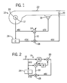
- Fig. 1 is a schematic illustration of a SISO active acoustic attenuation system implementing a filtered-X FIR control model.
- Fig. 2 is a block diagram illustrating the acoustic paths and control paths in the SISO system shown in Fig. 1, when the system is operating in attenuation mode to cancel acoustic energy.
- Fig. 3 is a block diagram illustrating acoustic paths and control paths in the SISO system designed in accordance with the invention, when the invention is operating in test mode to calculate the value of regressor-filter model C.
- Figs. 4a and 4b are phasor diagrams illustrating the calculation of the control parameters A(r, ⁇ ) which are used when the system is in test mode.
- Fig. 5 is a block diagram illustrating acoustic paths and control paths in a MIMO system designed in accordance with the invention when the system is operating in attenuation mode to cancel acoustic energy.
- Fig. 6 is a schematic illustration showing the operation of a MIMO system in accordance with the invention, when the system is operating in test mode to determine optimal values for parameters in C model channels for filtering the regressor signals.
- Fig. 1 shows an active acoustic attenuation system 10 with a feed forward adaptive control system implementing a filtered-X LMS update as is known in the art, and as is implemented in accordance with the invention.
- an input sensor 12 generates a reference signal x(k) that is processed by an adaptive control model A, block 14, to generate a correction signal y(k).
- the adaptive control model A, block 14, is preferably a transversal filter such as an FIR filter.
- the correction signal y(k) is transmitted to an output transducer 18.
- the output transducer 18 outputs a secondary input (i.e., a canceling acoustic wave) that combines with the system input (i.e., an input acoustic wave) to yield the system output (i.e. an output acoustic wave).
- An error sensor 20 senses the system output and generates an error signal e(k) in response thereto.
- the purpose of the system 10 shown in Fig. 1 is to cancel acoustic energy propagating through the duct 22 which is generated by the fan 24.
- the input sensor is a rotational position sensor, although other types of input sensors may be used.
- the output transducer 18 in Fig. 1 is a loudspeaker that injects a canceling acoustic wave into the duct 22.
- the adaptive control model A, block 14 is preferably a transversal finite impulse response (FIR) filter, although it should be apparent to those skilled in the art that the invention may be implemented by using an infinite impulse response (IIR) filter as described in U.S. Patent Nos. 4,677,676 and 4,677,677 which are hereby incorporated by reference herein.
- the filtered-X LMS algorithm as shown in Fig. 1 requires the filtering of the reference signal x(k) through C model, block 26, in order to form filtered regressor signals x'(k).
- the purpose of the C model 26 is to account for propagation delay and phase shifts in the auxiliary path SE in order to assure convergence of the LMS algorithm.
- Fig. 2 illustrates the acoustic paths and control paths in the system 10 shown in Fig. 1.
- block PE represents the acoustic path between the input sensor 12 and the error sensor 20
- block SE represents the auxiliary path between the output of control model A to the error sensor 20.
- Summing junction 20 in Fig. 2 represents the error sensor 20 shown in Fig. 1.
- the acoustic path PE and the auxiliary path SE while relatively stable, tend to change over relatively long periods of time.
- FIR or IIR adaptive control filters for control model A it is important to account for propagation delay and phase shifts in the auxiliary path SE.
- the invention relates primarily to the determination of the parameters of the C model, block 26.
- accurate determination of the C model optimizes adaptation of control model A.
- A - PE SE
- PE and SE are single complex values.
- PE is a p x m complex matrix
- SE is a p x n complex matrix
- m is the number of reference signals
- n is the number of correction signals
- p is the number of error signals.
- the pseudo inverse of SE is an n x p complex matrix
- control model A is an n x m complex matrix. More details of the preferred MIMO system are discussed below in connection with Figs. 5 and 6.
- an accurate estimate of the auxiliary path SE is obtained by operating the system 10t in test mode.
- the block Q represents an adaptive model that models the overall system from the input sensor 12 to the error sensor 20 including the uncontrolled physical path PE as well as the control path, blocks Atest and SE.
- a first set of values Atest(1) are selected for the control parameters for control model A. This is represented in Fig. 3 by block Atest.
- the system 10t is then operated in test mode to adaptively determine a solution Q(1) for the overall test model Q.
- model Q receives the reference signal x(k) as model input.
- Summer 29 inputs the model output from the Q model as well as the error signal e(k), and outputs a signal in line 31 that inputs the Q model as error input.
- the system 10t is first operated using a first version of the test control model Atest(1) to adaptively determine a first solution Q(1) of the overall system test model Q. The system is then operated in test mode using a second version of the test control model Atest(2) to adaptively determine a second solution Q(2) of the overall system test model.
- Atest(1), Q(1), Atest(2), and Q(2) the following set of linear equations is solved to determined PE and SE:
- the system 10 is then operated in attenuation mode as shown in Figs. 1 and 2 whereby the C model, block 26, is a copy of the solution for the auxiliary path SE determined by solving the set of linear equations in Equation (3).
- the C model, block 26 is a copy of the solution for the auxiliary path SE determined by solving the set of linear equations in Equation (3).
- test control parameters for the test control model Atest are represented as phasors for purposes of illustration, although the test parameters will typically be represented in other forms in practical applications, e.g. a complex number having an in-phase component and a quadrature component.
- Fig. 4a shows the preferred manner in selecting initial test values for the control parameters in the test control model Atest.
- the phasor labeled A(r, ⁇ ) initial represents an initially determined optimum value for the control parameters in control model A as determined by solving Equations (3) and (1).
- the control model A is an adaptive model, and this initially determined optimum value for the control model A may be used when the system initially begins attenuation mode.
- Atest(1) and Atest(2) could be selected arbitrarily, it may be convenient to select these values by shifting only 5%-15% form the then current version of A.
- the new values Atest(1) and Atest(2) shown in Fig. 4b are used to determine new values for Q(1) and Q(2), respectively, in order to solve Equation (3) to determine an updated value for the auxiliary path SE, and in turn the regressor filter C model, block 26.
- the invention is most useful for calculating the auxiliary path SE in systems having little physical change over time in the auxiliary path SE.
- the invention is also useful in tonal systems or other applications when it is not desired to inject low levels of random noise in order to accomplish adaptive modeling of the auxiliary path.
- a 1 x 2 x 2 MIMO system 100a is illustrated in attenuation mode as reference number 100a, Fig. 5, and in test mode as reference number 100t, Fig. 6. While Figs. 5 and 6 show the system 100 with one input sensor, two output transducers 18a, 18b and two error sensors 20a, 20b, the invention can generally be implemented in a system having m reference signals x(k), n correction signals, and p error signals. In such a system, there are m x p acoustic paths PE, n x p auxiliary paths SE. As shown in Fig. 5, the control model A has n x m model channels A 11 , A 21 .
- Each model channel A 11 , A 21 inputs one of the m reference signals x(k) and outputs one of n correction signals y(k).
- the system output is monitored by p error sensors, each outputting an error signal.
- n x p auxiliary paths SE In a generalized MIMO system, there are n x p auxiliary paths SE.
- Fig. 5 which is a 1 x 2 x 2 system, there are four auxiliary paths identified as SE 11 , SE 12 , SE 21 , and SE 22 .
- the system 100t must be operated in test mode in order to solve for the values of the various PE and SE paths. Analytically, this is done in a similar manner as with a SISO system. Test values are chosen for Atest11 and Atest21, and the system is operated to adaptively determine values for model channels Q 11 and Q 21 for the respective Atest values. Also, similar to the SISO system, additional sets of test values for Atest11 and Atest21 are selected to determine additional solutions for Q 11 and Q 21 . In a MIMO system, the test must be repeated at least m + n / m number of times to accumulate a sufficient number of linear equations in order to solve for each of the unknown PE and SE paths.
- Atestji(g) represents the test values for control parameters for the A model channel which receives the ith reference signal and outputs the jth correction signal for the gth test mode sampling
- Qki(g) represents the channel for the Q model that receives the ith reference signal and its output is combined with the kth error signal to generate an update signal for the gth test mode sampling.
- MIMO embodiment of the invention has been described in accordance with a 1 x 2 x 2 system by way of example, it should be apparent to those skilled in the art that the system has general applicability to MIMO systems having the dimensions m x n x p.
Applications Claiming Priority (2)
| Application Number | Priority Date | Filing Date | Title |
|---|---|---|---|
| US45221499A | 1999-12-01 | 1999-12-01 | |
| US452214 | 1999-12-01 |
Publications (2)
| Publication Number | Publication Date |
|---|---|
| EP1107225A2 true EP1107225A2 (de) | 2001-06-13 |
| EP1107225A3 EP1107225A3 (de) | 2003-05-02 |
Family
ID=23795563
Family Applications (1)
| Application Number | Title | Priority Date | Filing Date |
|---|---|---|---|
| EP00310640A Withdrawn EP1107225A3 (de) | 1999-12-01 | 2000-11-30 | Aktive Schalldämmungsanordnung, in welcher der Regressionsfilter von einem Gesamtsystem-Testmodel bestimmt wird |
Country Status (2)
| Country | Link |
|---|---|
| EP (1) | EP1107225A3 (de) |
| AU (1) | AU7147200A (de) |
Citations (2)
| Publication number | Priority date | Publication date | Assignee | Title |
|---|---|---|---|---|
| EP0814456A2 (de) * | 1996-06-17 | 1997-12-29 | Lord Corporation | Aktives Lärm- oder Schwingungskontrollesystem und -anordnung mit verstarkten Referenzsignalen |
| WO1998048508A2 (en) * | 1997-04-18 | 1998-10-29 | University Of Utah Research Foundation | Method and apparatus for multichannel active noise and vibration control |
-
2000
- 2000-11-08 AU AU71472/00A patent/AU7147200A/en not_active Abandoned
- 2000-11-30 EP EP00310640A patent/EP1107225A3/de not_active Withdrawn
Patent Citations (2)
| Publication number | Priority date | Publication date | Assignee | Title |
|---|---|---|---|---|
| EP0814456A2 (de) * | 1996-06-17 | 1997-12-29 | Lord Corporation | Aktives Lärm- oder Schwingungskontrollesystem und -anordnung mit verstarkten Referenzsignalen |
| WO1998048508A2 (en) * | 1997-04-18 | 1998-10-29 | University Of Utah Research Foundation | Method and apparatus for multichannel active noise and vibration control |
Non-Patent Citations (3)
| Title |
|---|
| JINWEI F ET AL: "A broadband self-tuning active noise equaliser" SIGNAL PROCESSING. EUROPEAN JOURNAL DEVOTED TO THE METHODS AND APPLICATIONS OF SIGNAL PROCESSING, ELSEVIER SCIENCE PUBLISHERS B.V. AMSTERDAM, NL, vol. 62, no. 2, 1 October 1997 (1997-10-01), pages 251-256, XP004100363 ISSN: 0165-1684 * |
| KUO S M ET AL: "ACTIVE NOISE CONTROL: A TUTORIAL REVIEW" PROCEEDINGS OF THE IEEE, IEEE. NEW YORK, US, vol. 87, no. 6, June 1999 (1999-06), pages 943-973, XP000912859 ISSN: 0018-9219 * |
| KUO S M ET AL: "Analysis and design of narrowband active noise control systems" ACOUSTICS, SPEECH AND SIGNAL PROCESSING, 1998. PROCEEDINGS OF THE 1998 IEEE INTERNATIONAL CONFERENCE ON SEATTLE, WA, USA 12-15 MAY 1998, NEW YORK, NY, USA,IEEE, US, 12 May 1998 (1998-05-12), pages 3557-3560, XP010279574 ISBN: 0-7803-4428-6 * |
Also Published As
| Publication number | Publication date |
|---|---|
| AU7147200A (en) | 2001-06-07 |
| EP1107225A3 (de) | 2003-05-02 |
Similar Documents
| Publication | Publication Date | Title |
|---|---|---|
| EP2242044B1 (de) | System zur aktiven Rauschregelung mit einem IRR-Filter | |
| CA2076007C (en) | Digital virtual earth active cancellation system | |
| US5687075A (en) | Adaptive control system | |
| EP2395501B1 (de) | Adaptive Geräuschsteuerung | |
| CA2082086C (en) | Correlated active attenuation system with error and correction signal input | |
| JP3346198B2 (ja) | 能動消音装置 | |
| JPH08509823A (ja) | 能動的音響及び振動制御のための単一及び多重チャネルブロック適応方法と装置 | |
| US5590205A (en) | Adaptive control system with a corrected-phase filtered error update | |
| EP0654901B1 (de) | Schnelles Konvergenzsystem eines adaptiven Filters zur Erzeugung eines zeitabhängigen Signals zur Kompensation eines primären Signals | |
| EP0616314B1 (de) | Vorrichtung zur aktiven Geräuschdämpfung mit adaptiver Steuerung | |
| GB2271908A (en) | Adaptive control for a noise cancelling system | |
| Kim et al. | Delayed-X LMS algorithm: An efficient ANC algorithm utilizing robustness of cancellation path model | |
| EP0525456B1 (de) | Anordnung mit mehreren digitalen adaptiven Filter | |
| EP1107225A2 (de) | Aktive Schalldämmungsanordnung, in welcher der Regressionsfilter von einem Gesamtsystem-Testmodel bestimmt wird | |
| EP1107226A2 (de) | Aktive Schalldämmungsanordnung auf der Basis von Gesamtsystem-Prüfmodellierung | |
| JPH1011074A (ja) | 電子消音装置 | |
| JP3419911B2 (ja) | 騒音キャンセルシステム | |
| Nam et al. | Adaptive active attenuation of noise using multiple model approaches | |
| KR100242087B1 (ko) | 엘티제이 필터를 이용한 능동 소음 및 진동 제어 장치 및 그 방법 | |
| JPH04358712A (ja) | 適応制御装置および適応形能動消音装置 | |
| JP2934928B2 (ja) | 適応型デジタルフィルタを用いた能動制御装置 | |
| JPH06332478A (ja) | 電子消音方法 | |
| WO1994001810A9 (en) | Low cost controller | |
| EP0659288A1 (de) | Preisgünstiger regler | |
| Wright et al. | Active noise control systems for controlling outdoor environmental noise |
Legal Events
| Date | Code | Title | Description |
|---|---|---|---|
| PUAI | Public reference made under article 153(3) epc to a published international application that has entered the european phase |
Free format text: ORIGINAL CODE: 0009012 |
|
| AK | Designated contracting states |
Kind code of ref document: A2 Designated state(s): AT BE CH CY DE DK ES FI FR GB GR IE IT LI LU MC NL PT SE TR |
|
| AX | Request for extension of the european patent |
Free format text: AL;LT;LV;MK;RO;SI |
|
| PUAL | Search report despatched |
Free format text: ORIGINAL CODE: 0009013 |
|
| AK | Designated contracting states |
Designated state(s): AT BE CH CY DE DK ES FI FR GB GR IE IT LI LU MC NL PT SE TR |
|
| AX | Request for extension of the european patent |
Extension state: AL LT LV MK RO SI |
|
| AKX | Designation fees paid | ||
| REG | Reference to a national code |
Ref country code: DE Ref legal event code: 8566 |
|
| STAA | Information on the status of an ep patent application or granted ep patent |
Free format text: STATUS: THE APPLICATION IS DEEMED TO BE WITHDRAWN |
|
| 18D | Application deemed to be withdrawn |
Effective date: 20031104 |