EP1107226A2 - Aktive Schalldämmungsanordnung auf der Basis von Gesamtsystem-Prüfmodellierung - Google Patents
Aktive Schalldämmungsanordnung auf der Basis von Gesamtsystem-Prüfmodellierung Download PDFInfo
- Publication number
- EP1107226A2 EP1107226A2 EP00310643A EP00310643A EP1107226A2 EP 1107226 A2 EP1107226 A2 EP 1107226A2 EP 00310643 A EP00310643 A EP 00310643A EP 00310643 A EP00310643 A EP 00310643A EP 1107226 A2 EP1107226 A2 EP 1107226A2
- Authority
- EP
- European Patent Office
- Prior art keywords
- model
- test
- control model
- control
- atest
- Prior art date
- Legal status (The legal status is an assumption and is not a legal conclusion. Google has not performed a legal analysis and makes no representation as to the accuracy of the status listed.)
- Withdrawn
Links
Images
Classifications
-
- G—PHYSICS
- G10—MUSICAL INSTRUMENTS; ACOUSTICS
- G10K—SOUND-PRODUCING DEVICES; METHODS OR DEVICES FOR PROTECTING AGAINST, OR FOR DAMPING, NOISE OR OTHER ACOUSTIC WAVES IN GENERAL; ACOUSTICS NOT OTHERWISE PROVIDED FOR
- G10K11/00—Methods or devices for transmitting, conducting or directing sound in general; Methods or devices for protecting against, or for damping, noise or other acoustic waves in general
- G10K11/16—Methods or devices for protecting against, or for damping, noise or other acoustic waves in general
- G10K11/175—Methods or devices for protecting against, or for damping, noise or other acoustic waves in general using interference effects; Masking sound
- G10K11/178—Methods or devices for protecting against, or for damping, noise or other acoustic waves in general using interference effects; Masking sound by electro-acoustically regenerating the original acoustic waves in anti-phase
- G10K11/1781—Methods or devices for protecting against, or for damping, noise or other acoustic waves in general using interference effects; Masking sound by electro-acoustically regenerating the original acoustic waves in anti-phase characterised by the analysis of input or output signals, e.g. frequency range, modes, transfer functions
- G10K11/17813—Methods or devices for protecting against, or for damping, noise or other acoustic waves in general using interference effects; Masking sound by electro-acoustically regenerating the original acoustic waves in anti-phase characterised by the analysis of input or output signals, e.g. frequency range, modes, transfer functions characterised by the analysis of the acoustic paths, e.g. estimating, calibrating or testing of transfer functions or cross-terms
- G10K11/17815—Methods or devices for protecting against, or for damping, noise or other acoustic waves in general using interference effects; Masking sound by electro-acoustically regenerating the original acoustic waves in anti-phase characterised by the analysis of input or output signals, e.g. frequency range, modes, transfer functions characterised by the analysis of the acoustic paths, e.g. estimating, calibrating or testing of transfer functions or cross-terms between the reference signals and the error signals, i.e. primary path
-
- G—PHYSICS
- G10—MUSICAL INSTRUMENTS; ACOUSTICS
- G10K—SOUND-PRODUCING DEVICES; METHODS OR DEVICES FOR PROTECTING AGAINST, OR FOR DAMPING, NOISE OR OTHER ACOUSTIC WAVES IN GENERAL; ACOUSTICS NOT OTHERWISE PROVIDED FOR
- G10K11/00—Methods or devices for transmitting, conducting or directing sound in general; Methods or devices for protecting against, or for damping, noise or other acoustic waves in general
- G10K11/16—Methods or devices for protecting against, or for damping, noise or other acoustic waves in general
- G10K11/175—Methods or devices for protecting against, or for damping, noise or other acoustic waves in general using interference effects; Masking sound
- G10K11/178—Methods or devices for protecting against, or for damping, noise or other acoustic waves in general using interference effects; Masking sound by electro-acoustically regenerating the original acoustic waves in anti-phase
- G10K11/1781—Methods or devices for protecting against, or for damping, noise or other acoustic waves in general using interference effects; Masking sound by electro-acoustically regenerating the original acoustic waves in anti-phase characterised by the analysis of input or output signals, e.g. frequency range, modes, transfer functions
- G10K11/17813—Methods or devices for protecting against, or for damping, noise or other acoustic waves in general using interference effects; Masking sound by electro-acoustically regenerating the original acoustic waves in anti-phase characterised by the analysis of input or output signals, e.g. frequency range, modes, transfer functions characterised by the analysis of the acoustic paths, e.g. estimating, calibrating or testing of transfer functions or cross-terms
- G10K11/17817—Methods or devices for protecting against, or for damping, noise or other acoustic waves in general using interference effects; Masking sound by electro-acoustically regenerating the original acoustic waves in anti-phase characterised by the analysis of input or output signals, e.g. frequency range, modes, transfer functions characterised by the analysis of the acoustic paths, e.g. estimating, calibrating or testing of transfer functions or cross-terms between the output signals and the error signals, i.e. secondary path
-
- G—PHYSICS
- G10—MUSICAL INSTRUMENTS; ACOUSTICS
- G10K—SOUND-PRODUCING DEVICES; METHODS OR DEVICES FOR PROTECTING AGAINST, OR FOR DAMPING, NOISE OR OTHER ACOUSTIC WAVES IN GENERAL; ACOUSTICS NOT OTHERWISE PROVIDED FOR
- G10K11/00—Methods or devices for transmitting, conducting or directing sound in general; Methods or devices for protecting against, or for damping, noise or other acoustic waves in general
- G10K11/16—Methods or devices for protecting against, or for damping, noise or other acoustic waves in general
- G10K11/175—Methods or devices for protecting against, or for damping, noise or other acoustic waves in general using interference effects; Masking sound
- G10K11/178—Methods or devices for protecting against, or for damping, noise or other acoustic waves in general using interference effects; Masking sound by electro-acoustically regenerating the original acoustic waves in anti-phase
- G10K11/1781—Methods or devices for protecting against, or for damping, noise or other acoustic waves in general using interference effects; Masking sound by electro-acoustically regenerating the original acoustic waves in anti-phase characterised by the analysis of input or output signals, e.g. frequency range, modes, transfer functions
- G10K11/17821—Methods or devices for protecting against, or for damping, noise or other acoustic waves in general using interference effects; Masking sound by electro-acoustically regenerating the original acoustic waves in anti-phase characterised by the analysis of input or output signals, e.g. frequency range, modes, transfer functions characterised by the analysis of the input signals only
- G10K11/17823—Reference signals, e.g. ambient acoustic environment
-
- G—PHYSICS
- G10—MUSICAL INSTRUMENTS; ACOUSTICS
- G10K—SOUND-PRODUCING DEVICES; METHODS OR DEVICES FOR PROTECTING AGAINST, OR FOR DAMPING, NOISE OR OTHER ACOUSTIC WAVES IN GENERAL; ACOUSTICS NOT OTHERWISE PROVIDED FOR
- G10K11/00—Methods or devices for transmitting, conducting or directing sound in general; Methods or devices for protecting against, or for damping, noise or other acoustic waves in general
- G10K11/16—Methods or devices for protecting against, or for damping, noise or other acoustic waves in general
- G10K11/175—Methods or devices for protecting against, or for damping, noise or other acoustic waves in general using interference effects; Masking sound
- G10K11/178—Methods or devices for protecting against, or for damping, noise or other acoustic waves in general using interference effects; Masking sound by electro-acoustically regenerating the original acoustic waves in anti-phase
- G10K11/1781—Methods or devices for protecting against, or for damping, noise or other acoustic waves in general using interference effects; Masking sound by electro-acoustically regenerating the original acoustic waves in anti-phase characterised by the analysis of input or output signals, e.g. frequency range, modes, transfer functions
- G10K11/17821—Methods or devices for protecting against, or for damping, noise or other acoustic waves in general using interference effects; Masking sound by electro-acoustically regenerating the original acoustic waves in anti-phase characterised by the analysis of input or output signals, e.g. frequency range, modes, transfer functions characterised by the analysis of the input signals only
- G10K11/17825—Error signals
-
- G—PHYSICS
- G10—MUSICAL INSTRUMENTS; ACOUSTICS
- G10K—SOUND-PRODUCING DEVICES; METHODS OR DEVICES FOR PROTECTING AGAINST, OR FOR DAMPING, NOISE OR OTHER ACOUSTIC WAVES IN GENERAL; ACOUSTICS NOT OTHERWISE PROVIDED FOR
- G10K11/00—Methods or devices for transmitting, conducting or directing sound in general; Methods or devices for protecting against, or for damping, noise or other acoustic waves in general
- G10K11/16—Methods or devices for protecting against, or for damping, noise or other acoustic waves in general
- G10K11/175—Methods or devices for protecting against, or for damping, noise or other acoustic waves in general using interference effects; Masking sound
- G10K11/178—Methods or devices for protecting against, or for damping, noise or other acoustic waves in general using interference effects; Masking sound by electro-acoustically regenerating the original acoustic waves in anti-phase
- G10K11/1785—Methods, e.g. algorithms; Devices
- G10K11/17853—Methods, e.g. algorithms; Devices of the filter
- G10K11/17854—Methods, e.g. algorithms; Devices of the filter the filter being an adaptive filter
-
- G—PHYSICS
- G10—MUSICAL INSTRUMENTS; ACOUSTICS
- G10K—SOUND-PRODUCING DEVICES; METHODS OR DEVICES FOR PROTECTING AGAINST, OR FOR DAMPING, NOISE OR OTHER ACOUSTIC WAVES IN GENERAL; ACOUSTICS NOT OTHERWISE PROVIDED FOR
- G10K11/00—Methods or devices for transmitting, conducting or directing sound in general; Methods or devices for protecting against, or for damping, noise or other acoustic waves in general
- G10K11/16—Methods or devices for protecting against, or for damping, noise or other acoustic waves in general
- G10K11/175—Methods or devices for protecting against, or for damping, noise or other acoustic waves in general using interference effects; Masking sound
- G10K11/178—Methods or devices for protecting against, or for damping, noise or other acoustic waves in general using interference effects; Masking sound by electro-acoustically regenerating the original acoustic waves in anti-phase
- G10K11/1787—General system configurations
- G10K11/17879—General system configurations using both a reference signal and an error signal
- G10K11/17881—General system configurations using both a reference signal and an error signal the reference signal being an acoustic signal, e.g. recorded with a microphone
-
- G—PHYSICS
- G10—MUSICAL INSTRUMENTS; ACOUSTICS
- G10K—SOUND-PRODUCING DEVICES; METHODS OR DEVICES FOR PROTECTING AGAINST, OR FOR DAMPING, NOISE OR OTHER ACOUSTIC WAVES IN GENERAL; ACOUSTICS NOT OTHERWISE PROVIDED FOR
- G10K11/00—Methods or devices for transmitting, conducting or directing sound in general; Methods or devices for protecting against, or for damping, noise or other acoustic waves in general
- G10K11/16—Methods or devices for protecting against, or for damping, noise or other acoustic waves in general
- G10K11/175—Methods or devices for protecting against, or for damping, noise or other acoustic waves in general using interference effects; Masking sound
- G10K11/178—Methods or devices for protecting against, or for damping, noise or other acoustic waves in general using interference effects; Masking sound by electro-acoustically regenerating the original acoustic waves in anti-phase
- G10K11/1787—General system configurations
- G10K11/17879—General system configurations using both a reference signal and an error signal
- G10K11/17883—General system configurations using both a reference signal and an error signal the reference signal being derived from a machine operating condition, e.g. engine RPM or vehicle speed
Definitions
- the invention relates generally to active acoustic attenuation systems that are designed to actively cancel tonal disturbances.
- the invention uses a novel method of determining a system control model, thereby improving system stability, sound quality and performance in tonal applications.
- Active acoustic attenuation involves the injection of a canceling acoustic wave to destructively interfere with and cancel a system input acoustic wave, thus yielding a system output.
- a control model inputs a reference signal and in turn supplies a correction signal to an output transducer (e.g., a loudspeaker in a sound application or a shaker in a vibration application).
- the output transducer injects the canceling acoustic wave or secondary input in order to destructively interfere with the system input so that the system output is zero or some other desired value.
- the system output acoustic wave is sensed with an error sensor such as a microphone in a sound system, or an accelerometer in a vibration system.
- C path modeling of the auxiliary path (SE) is used to account for delays and phase shifts.
- C modeling is often accomplished on-line by injecting low levels of random noise and using LMS techniques for the on-line C path modeling.
- the use of adaptive control algorithms such as the LMS or the RLMS and the use of random noise in C path modeling can be very effective.
- these techniques have disadvantages, particularly when attenuation of acoustic energy is intended only at discrete frequencies where tonal disturbances exist.
- C path modeling is undesirable in tonal systems because the addition of the random noise is usually noticeable.
- the random noise component added for C path modeling is typically vastly different in character than the tonal disturbance, thus making it very obvious when C path modeling is being performed.
- the added random noise is intrusive and objectionable.
- a strong disturbance tone corrupts the C path modeling process at the frequency of the disturbance, which is precisely the frequency where a good model is required. The corruption occurs because the signal-to-noise ratio at the required frequency is poor.
- C path modeling can be done using a very small adaptation step size and adapting over a long time period. However, this is generally undesirable.
- Another method used to overcome the model corruption problem is to use an active line enhancer or ALE.
- An ALE removes the disturbance tone from the modeling process, but this adds complexity to the overall algorithm.
- a third reason to avoid MIMO LMS-type adaptive models is the possibility that such models may get stuck in local, non-optimum minimum solutions. Even when local minimum do not exist, regions of very shallow gradient in the error surface can result in extremely long adaptation times.
- the preferred embodiment of the invention is an active acoustic attenuation system that is intended to attenuate relatively stationary tonal disturbances.
- the system has a control model A that is not a continuously adapting control filter. Rather, the system uses an overall system test model Q that adaptively models the entire system from the system input sensor to the error sensor, including the physical acoustic path PE and the control path A(SE).
- the overall system test model Q is implemented when the system is in test mode in order to initially determine and intermittently update the control model A.
- the control model A When the system is in attenuation mode, the control model A inputs a reference signal from an input sensor and outputs a correction signal which drives an output transducer. The output transducer outputs secondary input that combines with the system input to yield the system output. The control model A does not adapt and does not input an error signal while the system is operating to attenuate a tonal disturbance.
- the overall system test model Q adaptively models the entire system including the control model A and the output transducer. To do this, a first set of test values for adjustable control parameters Atest(1) in the control model A are selected, and the system is operated in test mode so that the overall system test model Q adapts to a solution Q(1) based on the test control model Atest(1).
- the overall system test model Q receives the reference signal as model input and receives a combination of the Q model output signal and the error signal as an error input. Then, a second set of test values Atest(2) are selected, and the system is again operated in test mode so that the overall system test model Q adapts to a solution Q(2) based on the test control model Atest(2).
- an optimum value for the control model A is then determined from Atest(1), Atest(2), Q(1), and Q(2), e.g., using linear algebra techniques.
- the system then operates in an attenuation mode in which the control model A is non-adapting to attenuate tonal disturbances. Intermittently, or whenever the acoustic energy represented by the error signal exceeds a threshold value, the control parameters in the control model A are updated by switching the system into test mode as described above.
- the technique is simple but also effective for relatively stationary tonal disturbances.
- the system automatically handles situations where the reference signal contains acoustic feedback from the output transducer (e.g. canceling loudspeaker).
- Benefits of the system include simplicity, stability, sound quality (no need for the addition of random noise), performance (avoidance of adaptation difficulties with LMS-type algorithms) and straightforward constraint application.
- the invention can also be implemented in multiple input, multiple output and multiple error (MIMO) systems.
- the present invention is applicable to sound attenuation systems, wherein the actuator is a loudspeaker, and the error sensor is a microphone.
- the input sensor may measure the rotational position of a machine causing the tonal disturbance.
- the input sensor may be a microphone, the system further comprising a phase-lock-loop circuit which inputs the reference signal outputting the input sensor before the reference signal inputs the overall system test model Q.
- the invention is also applicable to vibration control systems, wherein the error sensor is an accelerometer, and the actuator is an electromechanical shaker.
- an active acoustic attenuation system having a single system input and a single system output
- a method of attenuating tonal disturbances in the system comprising the steps of:
- the method may involve intermittently recalculating the values of the control parameters of the control model A in order to update the control model A by intermittently repeating steps a) through f) recited.
- control parameters for control model A may be represented by a phasor having a magnitude element and a phase element and updated versions of control model A may be recalculated by selecting subsequent test values for the adjustable control parameters in the test control models Atest(1) and Atest(2), the subsequent test values being selected by modifying the magnitude or phase of the adjustable control parameters of the current model A, and again operating the system in test mode.
- control parameters for control model A may be represented by a phasor having a magnitude element and a phase element
- test values for the test control models Atest(1) and Atest(2) which are selected for updating the control model A may be selected such that the magnitude element of Atest(1) has the same magnitude as the magnitude element of the current version of the control model A and the phase element of Atest (1) is shifted with respect to the phase element of the then current version of control model A, and such that the magnitude element of Atest(2) is the same magnitude as the magnitude element of the then current version of control model A and the phase element of Atest(2) is shifted from the phase element of the then current version of control model A, and also shifted in a direction opposite to the selected value for Atest(1).
- control parameters for control model A may be represented by a phasor having a magnitude element and a phase element
- test values for the test control models Atest(1) and Atest(2) which are selected for updating the control model A may be selected such that the magnitude element of Atest(1) has the same magnitude as the magnitude element of the current version of the control model A and the phase element of Atest (1) is shifted with respect to the phase element of the then current version of control model A, and such that the magnitude element of Atest(2) is the same magnitude as the magnitude element of the then current version of control model A and the phase element of Atest(2) is also equal to the phase element of the then current version of control model A.
- control parameters for the control model A may be represented by a complex number having an in-phase component and a quadrature component
- test values for the test control models Atest(1) and Atest(2) which are selected for updating the control model A may be selected by making relatively small changes to the in-phase component and the quadrature component of the current version of the control model A.
- the method may alternatively involve recalculating the value of the control parameters in the control model A when the error signal represents an amount of acoustic energy in the system output that exceeds a preselected value, the recalculation of the values of the control parameters for the control model A being accomplished by repeating steps a) through f).
- an active acoustic attenuation system having a system input and a system output, the system comprising:
- the adaptive parameters for the n x m model channels for control model A are determined in accordance with the following steps:
- the adjustable control parameters for the channels A ji for the control model A may be represented by a phasor having a magnitude element and a phase element.
- Updated versions of the channels Aji for the control model A may be recalculated by selecting subsequent test values for the adjustable control parameters in the channels Atestji(g) for the test control model channels, and said subsequent test values may be selected by modifying the magnitude or phase of the current version of the control parameters for the respective channel model A ji .
- the adjustable control parameters for the channels A ji for the control model A may each be represented by a complex number having an in-phase component and a quadrature component.
- the system may be designed to attenuate sound, the output transducers being loudspeakers, and the error sensors being microphones.
- At least one of the input sensors may sense rotational position.
- At least one of the output transducers may be an electromechanical shaker.
- an active acoustic attenuation system having a system input and a system output
- a method of attenuating tonal disturbances comprising the steps of:
- the channels A ji of the control model A may be calculated by solving a set of linear equations relating to test values for the channels of the overall system test model Qki(g) and the channels of the test control model Atestji(g) to determine unknown acoustic and electrical paths in the system.
- the method may further comprise the step of filtering each reference signal through a phase-lock-loop circuit before the reference signal inputs the respective channel for the overall system test model Q.
- the values of the control parameters for the control model channels A ji may be recalculated intermittently.
- the value of the control parameters for the control model A may be recalculated when an amount of acoustic energy in the system output represented by the error signals exceeds a preselected threshold value.
- the adjustable control parameters for the channels Aji for the control model A may each include two phasor elements, a magnitude element and a phase element, and updated versions of the channels Aji for the control model A may be recalculated by selecting subsequent test values for the adjustable control parameters and the channels Atestji(g) for the test control model channels, and said subsequent test values may be selected by modifying the magnitude or phase of the current version of the control parameters for the respective channel model Aji.
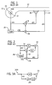
- Fig. 1 is a schematic illustration of SISO active acoustic attenuation system implementing an adaptive FIR filter as is known in the art in which the input sensor is a tachometer.
- Fig. 2 is a block diagram illustrating the acoustic paths and control paths in the prior art SISO system shown in Fig. 1.
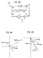
- Fig. 3a is a block diagram illustrating acoustic paths and control paths in a SISO system designed in accordance with the invention, when the system is operating in attenuation mode to cancel a tonal disturbance.
- Fig. 3b is a block diagram illustrating acoustic paths and control paths in a SISO system designed in accordance with the invention, and when the system is operating in test mode to determine an optimum value for control model A.
- Figs. 4a and 4b are phasor diagrams illustrating the calculation of control parameters A(r, ⁇ ) for control model A.
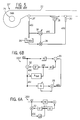
- Fig. 5 is a schematic illustration showing a prior art SISO active acoustic attenuation system implementing an adaptive LMS filter, which is similar to the system shown in Fig. 1 except that the input sensor in Fig. 5 is a microphone.
- Fig. 6a is a block diagram illustrating acoustic paths and control paths in a SISO system designed in accordance with the invention in which the input sensor is exposed to acoustic feedback, and when the system is operating in attenuation mode to cancel a tonal disturbance.
- Fig. 6b is a block diagram illustrating acoustic paths and control paths in a SISO system designed in accordance with the invention in which the input sensor is exposed to acoustic feedback, and when the system is operating in test mode to determine an optimum value for control model A.
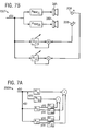
- Fig. 7a is a block diagram illustrating acoustic paths and control paths in a MIMO system designed in accordance with the invention when the system is operating in attenuation mode to cancel one or more tonal disturbances.
- Fig. 7b is a schematic illustration showing the operation of a multiple input, multiple output, multiple error (MIMO) system in accordance with the invention, when the system is operating in test mode to determine optimal values for control parameters in channels of control model A.
- MIMO multiple input, multiple output, multiple error
- Fig 1 shows an active acoustic attenuation system 10 with a feed forward adaptive control system implementing a filtered-X LMS update as is known in the art.
- an input sensor 12 generates a reference signal x(k) that is processed by adaptive A filter 14 to generate a correction signal y(k).
- the correction signal y(k) is transmitted to an output transducer 18.
- the output transducer 18 outputs a secondary input (i.e. a canceling acoustic wave) that combines with the system input (i.e. an input acoustic wave) to yield the system output (i.e. an output acoustic wave).
- An error sensor 20 senses the system output and generates an error signal e(k) in response thereto.
- the purpose of the prior art system 10 shown in Fig. 1 is to cancel acoustic tones (i.e. tonal disturbances) propagating through duct 22, which are generated by fan 24.
- the input sensor 12 is a tachometer which senses the rotational speed of the fan, and is isolated from acoustic feedback.
- the output transducer 18 in Fig. 1 is a loudspeaker which injects a canceling acoustic wave into the duct 22.
- the adaptive A filter 14 is typically a transversal finite impulse response (FIR) filter, or possibly an infinite impulse response (IIR) filter as described in U.S. Patent Nos. 4,677,676 and 4,677,677.
- FIR transversal finite impulse response
- IIR infinite impulse response
- Fig. 2 illustrates the acoustic paths and control paths in the system 10 shown in Fig. 1.
- block PE represents the acoustic path between the input sensor 12 and the error sensor 20
- block SE represents the auxiliary path from the output of control model A to the error sensor 20.
- Summing junction 20 in Fig. 2 represents the error sensor 20 shown in Fig. 1.
- the acoustic path PE and the auxiliary path SE while relatively stable, tend to change over relatively long periods of time.
- the multiplier 28 combines the filtered regressor signal x'(k) with the error signal e(k) to provide error input to the adaptive control filter A via line 30.
- the invention eliminates the need for directly modeling the auxiliary path SE (i.e., eliminates the need for filtering a regressor signal with a C model copy 26), and also avoids the use of adaptive FIR or IIR filters, both of which may unnecessarily complicate and possibly compromise system performance when the system is designed to cancel tonal disturbances in contrast to broadband acoustic energy.
- the prior art system 10f shown in Fig. 5 is similar in many respects to the system 10 shown in Fig. 1 except that the input sensor 12f shown in Fig. 5 is a microphone, rather than a tachometer 12. Analytically, one of the primary differences between the system 10 shown in Fig. 1 and the system 10a shown in Fig. 5 is that the input microphone 12f in Fig. 5 is exposed to acoustic feedback from the output transducer 18. It is well known in the art (e.g. U.S. Patent Nos. 4,677,676 and 4,677,677) that the filtered-X FIR and filtered-U IIR methods are capable of accommodating acoustic feedback from the output transducer 18 to the input sensor 12a. In other respects, the prior art system 10a shown in Fig. 5 is similar to the prior art system 10 shown in Figs. 1 and 2.
- Figs. 3a and 3b are block diagrams illustrating a SISO active acoustic attenuation system 100 that operates in accordance with the invention.
- the illustrated system is one in which the input sensor is isolated from acoustic feedback from the output transducer 18, such as a sensor sensing rotational position of a fan.
- Fig. 3a illustrates the system operating in attenuation mode and is identified by reference numeral 100a
- Fig. 3b illustrates the system operating in test mode and is identified by reference numeral 100t.
- the system 100a attenuates tonal disturbances in the system input when PE and SE are relatively stationary, and when a suitable reference signal x(k) is available.
- the reference signal x(k) inputs control model A which processes the signal and outputs a correction signal y(k) to the output transducer.
- the control model A contains adjustable control parameters which can be represented as a phasor having a magnitude element and a phase element; or alternatively a single complex number having an in-phase component and a quadrature component.
- Block PE represents a transfer function of the physical system without any control from the input sensor 12 to the error sensor 20.
- the input sensor 12 preferably measures rotational position of the fan.
- Block SE represents a transfer function from the output of the control model A to the error sensor 20.
- the solution for control model A is calculated directly from the transfer functions PE and SE.
- PE is a p x m complex matrix
- SE is a p x n complex matrix, where m is the number of reference signals, n is the number of correction signals, and p is the number of error signals.
- the pseudo inverse of SE is an n x p complex matrix and control model A is an n x m complex matrix. More details of the preferred MIMO system are discussed below in connection with Figs. 7a and 7b.
- Equation (1) For direct calculation of Equation (1) to be effective, accurate estimates of PE and SE are required at the disturbance frequency. Estimates of PE and SE, and in turn the values for the adjustable control parameters in control model A, are preferably calculated and recalculated from time to time by operating the system in test mode as shown in Fig. 3b.
- the block Q represents an adaptive model that models the overall system from the input sensor 12 to the error sensor 20 including the uncontrolled physical path PE as well as the control path, blocks Atest and SE.
- a first set of test values Atest(1) are selected for the control parameters for control model A. This is represented in Fig. 3b by block Atest.
- the system 100t is then operated in test mode to adaptively determine a solution Q(1) for the overall test model Q.
- model Q receives the reference signal x(k) as model input.
- Summer 29 inputs the model output from the Q model as well as the error signal e(k), and outputs a signal in line 31 that inputs the Q model as error input.
- Adaptation of overall system test model Q in the test mode is generally a much safer and more reliable process than continuously adapting a control model using the LMS algorithm since controller output is not directly affected by possible instabilities in the Q model.
- the following set of linear equations is solved to determine PE and SE:
- the optimum value for the control model A is determined by using the solutions for PE and SE from Equation (3) to solve Equation (1).
- the system is then operated to cancel the tonal disturbance using the optimum value for control model A.
- control model A it may be desirable to recalculate the optimum value for control model A in order to accommodate changes in PE or SE over time. It may be desirable to recalculate control model A at prescheduled intervals, or when the acoustic energy in the system output represented by the error signal exceeds a preselected threshold value.
- the control parameters are represented as phasors.
- the control parameters can also take other forms, such as a complex number having an in-phase component and a quadrature component, however, phasor representation is particularly well suited for illustration.
- the phasor labeled A(r, ⁇ ) initial represents the initially determined optimum value for the control parameters in control model A as determined by solving Equations (3) and (1) as previously described.
- Figs. 6a and 6b the technique is also valid when the reference signal x(k) contains acoustic feedback from the output transducer 18 (see Fig. 5).
- prior art techniques are able to accommodate acoustic feedback to an input microphone 12f, such as shown in Fig. 5.
- Fig. 6a shows a system 101a in accordance with the invention operating to cancel tonal disturbances in the system input
- Fig. 6b shows the system 101t operating in test mode to determine the optimum value for control model A.
- acoustic feedback from the output transducer to the input microphone is represented by block SF and summing junction 32.
- the tonal disturbance in the system input is represented by v(k) whereas the reference signal that inputs the control model A in Fig. 6a is x(k).
- the reference signal that inputs the test control model Atest and the overall system test model Q in Fig. 6b is x(k).
- the reference signal x(k) should be a clean sine wave in order for this technique to be effective.
- input sensors that are exposed to acoustic feedback at the disturbance frequency also tend to pick up other noise signals.
- the noise can corrupt the overall system modeling process for test model Q, and result in non-optimal performance. This is particularly important in MIMO systems since small errors in Q model channels can result in large errors in the calculated optimal control model channels A.
- a phase-lock-loop circuit and a gain control circuit should normally be used to clean and normalize the reference signal x(k).
- the invention is most useful for attenuating tonal disturbances in systems having little if any physical change over time.
- the invention is also useful in systems having long periods of nearly stationary behavior with short periods of rapidly varying characteristics. In such cases, adaptation is preferably disabled during the rapidly changing periods.
- Applications such as industrial silencing of fans and blowers are logical, as well as aerospace and large engine sound and vibration applications which run for significant periods of time at the same or similar throttle settings.
- a 1 x 2 x 2 MIMO system 200a is illustrated in attenuation mode to cancel tonal disturbances in the system input (Fig. 7a), and in test mode (200t in Fig. 7b). While Figs. 7a and 7b show the system 200 with one input sensor, two output transducers 18a, 18b and two error sensors 20a, 20b, the invention can generally be implemented in a system having m reference signals x(k), n correction signals, and p error signals. In such a system, there are m x p acoustic paths PE, and n x p auxiliary paths SE. As shown in Fig.
- the control model A has n x m model channels A 11 , A 21 .
- Each model channel A 11 , A 21 inputs one of the m reference signals x(k) and outputs one of n correction signals y(k).
- the system output is monitored by p error sensors, each outputting an error signal.
- a generalized MIMO system there are n x p auxiliary paths SE.
- Fig. 7a which is a 1 x 2 x 2 system, there are four auxiliary paths identified as SE 11 , SE 12 , SE 21 , and SE 22 .
- the system 200t must be operated in test mode in order to solve for the values of the various PE and SE paths. Analytically, this is done in a similar manner as with a SISO system. Test values are chosen for Atestl 1 and Atest21, and the system is operated to adaptively determine values for model channels Q(1) 1 and Q(2) 1 for the respective Atest values. Also, similar to the SISO system, additional sets of test values for Atestl 1 and Atest21 are selected to determine additional solutions for Q 11 and Q 21 .
- the test In a MIMO system, the test must be repeated at least m + n / m number of times to accumulate a sufficient number of linear equations in order to solve for each of the PE and SE paths necessary for determining the optimum value of the channels in the control model A.
- MIMO embodiment of the invention has been described in accordance with a 1 x 2 x 2 system by way of example, it should be apparent to those skilled in the art that the system has general applicability to MIMO systems having the dimensions m x n x p.
- MIMO system 200 illustrated in Figs. 7a and 7b does not specifically illustrate that the system is capable of accommodating acoustic feedback in the reference signals x(k) from the output transducers, the system would normally be capable of accommodating acoustic feedback in the reference signal.
- the operation is similar to that illustrated with respect to the SISO system shown in Figs. 6a and 6b.
Landscapes
- Physics & Mathematics (AREA)
- Engineering & Computer Science (AREA)
- Acoustics & Sound (AREA)
- Multimedia (AREA)
- Soundproofing, Sound Blocking, And Sound Damping (AREA)
- Measurement Of Mechanical Vibrations Or Ultrasonic Waves (AREA)
Applications Claiming Priority (2)
| Application Number | Priority Date | Filing Date | Title |
|---|---|---|---|
| US45221399A | 1999-12-01 | 1999-12-01 | |
| US452213 | 1999-12-01 |
Publications (2)
| Publication Number | Publication Date |
|---|---|
| EP1107226A2 true EP1107226A2 (de) | 2001-06-13 |
| EP1107226A3 EP1107226A3 (de) | 2003-05-02 |
Family
ID=23795556
Family Applications (1)
| Application Number | Title | Priority Date | Filing Date |
|---|---|---|---|
| EP00310643A Withdrawn EP1107226A3 (de) | 1999-12-01 | 2000-11-30 | Aktive Schalldämmungsanordnung auf der Basis von Gesamtsystem-Prüfmodellierung |
Country Status (2)
| Country | Link |
|---|---|
| EP (1) | EP1107226A3 (de) |
| AU (1) | AU7149300A (de) |
Cited By (1)
| Publication number | Priority date | Publication date | Assignee | Title |
|---|---|---|---|---|
| WO2006050699A1 (de) * | 2004-11-09 | 2006-05-18 | Schaeffler Kg | Verfahren zur bestimmung der schallübertragungsfunktion und zur dämpfung der schallübertragung eines lagersystems |
Family Cites Families (3)
| Publication number | Priority date | Publication date | Assignee | Title |
|---|---|---|---|---|
| US5625684A (en) * | 1993-02-04 | 1997-04-29 | Local Silence, Inc. | Active noise suppression system for telephone handsets and method |
| US5844996A (en) * | 1993-02-04 | 1998-12-01 | Sleep Solutions, Inc. | Active electronic noise suppression system and method for reducing snoring noise |
| CA2148962C (en) * | 1994-05-23 | 2000-03-28 | Douglas G. Pedersen | Coherence optimized active adaptive control system |
-
2000
- 2000-11-09 AU AU71493/00A patent/AU7149300A/en not_active Abandoned
- 2000-11-30 EP EP00310643A patent/EP1107226A3/de not_active Withdrawn
Cited By (1)
| Publication number | Priority date | Publication date | Assignee | Title |
|---|---|---|---|---|
| WO2006050699A1 (de) * | 2004-11-09 | 2006-05-18 | Schaeffler Kg | Verfahren zur bestimmung der schallübertragungsfunktion und zur dämpfung der schallübertragung eines lagersystems |
Also Published As
| Publication number | Publication date |
|---|---|
| AU7149300A (en) | 2001-06-21 |
| EP1107226A3 (de) | 2003-05-02 |
Similar Documents
| Publication | Publication Date | Title |
|---|---|---|
| EP0521868B1 (de) | Aktives digitales annulationssystem "virtuelle erde" | |
| EP2242044B1 (de) | System zur aktiven Rauschregelung mit einem IRR-Filter | |
| US6847721B2 (en) | Active noise control system with on-line secondary path modeling | |
| EP0721179B1 (de) | Adaptiver Tonbestimmungsanordnung mit begrenstem und adaptivem Ausgang | |
| CA2122108C (en) | Multiple adaptive filter active noise canceller | |
| JP3346198B2 (ja) | 能動消音装置 | |
| JP5255087B2 (ja) | 適応性ノイズコントロール | |
| JP5640063B2 (ja) | 調整可能なアクティブ雑音制御 | |
| EP0712115B1 (de) | Aktive Lärm und Vibration Kontrollanordnung mit Rücksicht auf Zeitvariationen in der Anordnung unter Benutzung des residuellen Signals zur Erzeugung des Probesignals | |
| EP0773531B1 (de) | Frequenzselektiver aktiver adaptiver Steuerungsanordnung | |
| EP0654901B1 (de) | Schnelles Konvergenzsystem eines adaptiven Filters zur Erzeugung eines zeitabhängigen Signals zur Kompensation eines primären Signals | |
| JPH0567948A (ja) | 適応型デイジタルフイルタ | |
| EP0742971A1 (de) | Adaptiv vor- und rückwärts geregeltes system | |
| EP0555585A2 (de) | Korrelierte Aktiverdampfungsanordnung mit Fehler- und Korrektions-Eingangssignal | |
| CN116438597A (zh) | 用于适应所估计的次级路径的系统和方法 | |
| CN113470607A (zh) | 有源振动噪音降低系统 | |
| Kim et al. | Delayed-X LMS algorithm: An efficient ANC algorithm utilizing robustness of cancellation path model | |
| EP0525456B1 (de) | Anordnung mit mehreren digitalen adaptiven Filter | |
| EP1107226A2 (de) | Aktive Schalldämmungsanordnung auf der Basis von Gesamtsystem-Prüfmodellierung | |
| EP1308926B1 (de) | Aktives Lärmunterdrückungssystem mit Frequenzansprechkontrolle | |
| EP1107225A2 (de) | Aktive Schalldämmungsanordnung, in welcher der Regressionsfilter von einem Gesamtsystem-Testmodel bestimmt wird | |
| EP0530523B1 (de) | Aktiver Schalldämpfer mit verbessertem Verfahren zur Koeffizientensequenzselektion | |
| KR19990042877A (ko) | 자동차의 능동 소음 제어방법 | |
| JP4516774B2 (ja) | 振動制御システム | |
| JPH09171388A (ja) | 適応フィルタ |
Legal Events
| Date | Code | Title | Description |
|---|---|---|---|
| PUAI | Public reference made under article 153(3) epc to a published international application that has entered the european phase |
Free format text: ORIGINAL CODE: 0009012 |
|
| AK | Designated contracting states |
Kind code of ref document: A2 Designated state(s): AT BE CH CY DE DK ES FI FR GB GR IE IT LI LU MC NL PT SE TR |
|
| AX | Request for extension of the european patent |
Free format text: AL;LT;LV;MK;RO;SI |
|
| PUAL | Search report despatched |
Free format text: ORIGINAL CODE: 0009013 |
|
| AK | Designated contracting states |
Designated state(s): AT BE CH CY DE DK ES FI FR GB GR IE IT LI LU MC NL PT SE TR |
|
| AX | Request for extension of the european patent |
Extension state: AL LT LV MK RO SI |
|
| 17P | Request for examination filed |
Effective date: 20030616 |
|
| R17P | Request for examination filed (corrected) |
Effective date: 20030708 |
|
| AKX | Designation fees paid |
Designated state(s): DE GB |
|
| 17Q | First examination report despatched |
Effective date: 20041019 |
|
| STAA | Information on the status of an ep patent application or granted ep patent |
Free format text: STATUS: THE APPLICATION IS DEEMED TO BE WITHDRAWN |
|
| 18D | Application deemed to be withdrawn |
Effective date: 20050301 |