EP1107002B1 - Vorrichtung und Verfahren zur Trennung von Bestandteilen einer flüssigen Probe - Google Patents
Vorrichtung und Verfahren zur Trennung von Bestandteilen einer flüssigen Probe Download PDFInfo
- Publication number
- EP1107002B1 EP1107002B1 EP00125383A EP00125383A EP1107002B1 EP 1107002 B1 EP1107002 B1 EP 1107002B1 EP 00125383 A EP00125383 A EP 00125383A EP 00125383 A EP00125383 A EP 00125383A EP 1107002 B1 EP1107002 B1 EP 1107002B1
- Authority
- EP
- European Patent Office
- Prior art keywords
- bag
- tube
- collection device
- condition
- liquid
- Prior art date
- Legal status (The legal status is an assumption and is not a legal conclusion. Google has not performed a legal analysis and makes no representation as to the accuracy of the status listed.)
- Expired - Lifetime
Links
Images


Classifications
-
- B—PERFORMING OPERATIONS; TRANSPORTING
- B01—PHYSICAL OR CHEMICAL PROCESSES OR APPARATUS IN GENERAL
- B01L—CHEMICAL OR PHYSICAL LABORATORY APPARATUS FOR GENERAL USE
- B01L3/00—Containers or dishes for laboratory use, e.g. laboratory glassware; Droppers
- B01L3/50—Containers for the purpose of retaining a material to be analysed, e.g. test tubes
- B01L3/502—Containers for the purpose of retaining a material to be analysed, e.g. test tubes with fluid transport, e.g. in multi-compartment structures
- B01L3/5021—Test tubes specially adapted for centrifugation purposes
- B01L3/50215—Test tubes specially adapted for centrifugation purposes using a float to separate phases
Definitions
- This invention relates to a device for separating heavier and lighter fractions of a fluid sample. More particularly, this invention relates to a device for collecting and transporting fluid samples whereby the device and fluid sample are subjected to centrifugation in order to cause separation of the heavier fraction from the lighter fraction of the fluid sample.
- Diagnostic tests may require separation of a patient's whole blood sample into components, such as serum or plasma, the lighter phase component, and blood cells, the heavier phase component.
- Samples of whole blood are typically collected by venipuncture through a cannula or needle attached to a syringe or an evacuated collection tube. Separation of the blood into serum and blood cells is then accomplished by rotation of the syringe or tube in a centrifuge.
- Such arrangements use a barrier for moving into an area adjacent the two phases of the sample being separated in order to maintain the components separated for subsequent examination of the individual components.
- a variety of devices have been used in collection and separation devices to divide the heavier and lighter phases of a fluid sample.
- the most widely used device includes thixotropic gel material such as polyester or silicone gels.
- the present gel serum separation tubes require special manufacturing equipment to prepare the gel and to fill the tubes.
- the shelf-life of the product is limited in that over time unbound resin may be released from the gel mass.
- This resin may have a specific gravity that is less than or equal to the separated serum and may float in the serum and may clog the measuring instruments such as the instrument probes used during the clinical examination of the sample collected in the tube. Such clogging can lead to considerable downtime for the instrument to remove the clog.
- a collection device corresponding to the introductory part of claim 1 is disclosed in US-A-4,569,764.
- This collection device comprises a collection tube containing a flowable liquid separation medium retained in a deformable container.
- the separation medium flows to the interface between the two phases during centrifugation and provides a barrier between the separated phases.
- the collection device of the present invention is defined by claim 1. Accordingly, the collection device is characterized in that the container containing the separation medium in sealed containment and being deformably repositionable with said centrifugation from a first condition permitting said liquid collection within said tube to a second condition whereby the container and the liquid separation medium contained therewith establish physical separation between said separated liquid phases.
- the present invention is an assembly for separating a fluid sample into a higher specific gravity phase and a lower specific gravity phase.
- the assembly of the present invention comprises a plurality of constituents.
- the assembly comprises a container, such as a tube, a deformable container, such as a bag, and a flowable separation medium.
- the deformable container is provided for positioning within a tube and includes a flowable fluid separation medium capable of maintaining separation of the separated fluid phases.
- the deformable container is deformably repositionable under centrifugation from a first condition permitting a fluid sample within the tube to a second condition establishing a physical separation between the separated fluid phases.
- the deformable container includes a flexible bag which is reconfigurable under centrifugation from a first condition to a second condition.
- the flowable fluid separation medium preferably includes a thixotropic fluid such as a gel having a specific gravity, which under centrifugation, becomes resident between the separated fluid sample phases.
- the flexible bag may be adheringly secured to the inner wall of the tube so as to provide for the deformable movement of the bag and the gel contained therein from a position adjacent the lower end of the tube to an intermediate position within the tube under centrifugation so as to establish residence of the gel in the bag between the separated fluid phases of the fluid sample.
- the flexible bag is preferably sealed with the gel completely contained therein.
- the assembly of the present invention is advantageous over existing separation products that use gel.
- One advantage is that the assembly of the present invention will not interfere with analytes as compared to gels that may interfere with analytes. In particular, the assembly will not interfere with therapeutic drug monitoring analytes.
- Another notable advantage of the present invention is that fluid specimens are not subjected to low density residuals such as unbound resins that are at times available in products that use gel.
- the assembly of the present invention does not require any additional steps or treatment by a medical practitioner whereby a blood or fluid sample is drawn in the conventional way, using standard sampling equipment.
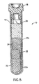
- Assembly 10 includes a collection tube 12 having an upper end 13 , a lower end 14 and a cylindrical wall 15 extending therebetween.
- the upper end 13 includes an opening 13a, while lower end 14 is closed by an integrally formed bottom 14a.
- a tube interior 16 is defined between upper and lower ends 13 and 14.
- Opening 13a of upper end 13 of tube 12 may be closed by a stopper 18 which is made of a suitable elastomer material.
- both ends of the tube may be open and both ends of the tube may be sealed by elastomeric closures.
- At least one of the closures of the tube may include a resealable septum.
- Fluid phase partition device 20 supportsed within tube 12 .
- Fluid phase partition device 20 includes a deformable container or flexible bag 22 and a thixotropic separation medium or a Gel 24 contained within bag 22 .
- Bag 22 may be a flexible deformable bag which is subject to being reconfigured upon an application of force. Bag 22 may be formed from a wide variety of both elastic and inelastic materials such as polyethylene, polyurethane or syran and which does not adversely interact with the fluid sample which would come in contact with the bag. The size of the bag is selected such that if the bag were to be completely or partially expanded it would have a dimension which would exceed the diameter of tube 12 . Bag 22 is thus expandable into a configuration where it may be placed in frictional engagement with the inner surface 15a of cylindrical wall 15 of tube 12. Bag 22 while being deformably flexible and pliable has sufficient strength so as to permit bag deformation without risk of rupturing of the bag. Bag 22 may be formed with conventional forming techniques such as film extrusion or blow molding.
- bag 22 contains a gel 24 in sealed containment therein.
- Gel 24 is selected so that it becomes resident between the separated phases of a fluid sample.
- gel 24 is selected to have a specific gravity intermediate the specific gravities of the lighter serum or plasma phase and the heavier cellular phase of a blood sample.
- gel 24 When subjected to forces such as centrifugal forces, gel 24 becomes flowable. Upon cessation of such centrifugal forces, gel 24 may return to its non-flowable state.
- Gel 24 of the present invention may be a single component gel or may formed of various combinations of gels and fluids.
- Gel 24 may include silicones or oils or mixtures thereof such as mixtures of silicon and hydrophobic silicon dioxide powders or a mixture of liquid polybutane polymer and silicon dioxide powder. While these specific examples are provided, gel 24 can be of any material which is movable under centrifugal force to form a barrier between the separated blood phases of a blood sample. In an alternative embodiment, a highly viscous material, rather than a gel, may be used.
- gel 24 fills only a portion 22b of bag 22 with the remaining portion 22a of the bag being collapsed and substantially absent of gel.
- Bag 22 is inserted into tube 12 and positioned in lower end 14 of tube 12. Bag 22 may be secured adjacent bottom 14a oftube 12 by using a suitable adhesive. Adhesive may be applied between bag 22 and inner surface 15a of cylindrical side wall 15 of tube 12 adjacent bottom 14a. It is contemplated that bag 22 may also be secured to inner surface 15a at one or more locations along the length of tube 12 . While an applied adhesive may be used to secure bag 22 to inner surface 15a of tube 12, it is contemplated that the bag itselfmay be formed of materials which have sufficient tackiness to promote adherence of bag 22 to inner surface 15a of tube 12. In an alternative embodiment, the flexible bag is not attached within the tube but is free to move with the gel.
- liquid sample 30 is delivered into interior 16 of a collection tube 12 by a needle 19 that pierces through elastomeric stopper 18 and then the needle is removed and the stopper reseals.
- the liquid sample is blood.
- Liquid sample 30 substantially fills interior 16 of tube 12 between bag 22 and upper end 13 of tube 12 .
- Tube 12 is then placed in a centrifuge device such that closed lower end 14 will be positioned radially outward of stopper 18 and the axis of rotation of the centrifuge during centrifugation.
- blood cells and other components of the heavy or higher density cellular phase 32 move toward closed lower end 14 of tube 12 .
- the lighter or lower density phase components such as plasma or serum move toward open end 13 .
- gel 24 moves within bag 22 from a position adjacent the closed lower end 14 of tube 12 towards upper end 13 to reside at a position intermediate opposed upper and lower ends 13 and 14 .
- Serum or plasma is squeezed upwardly and cells are squeezed downwardly at the interface. Bag 22 forms a physical separation between the separated phases.
- lower portion 22b of bag 22 collapses while upper portion 22a of bag 22 that is filled with gel 24 provides separation between the lighter phase blood components 34 such as plasma or serum and the heavier phase cellular blood components 32 .
- Bag 42 is substantially similar to bag 22 described above with a portion of its maximum volume filled with Gel 44 of the type described above.
- bag 42 is inserted into interior 16 of tube 12 and is not adhesively retained in the lower end.
- the bag upon centrifugation, the bag deformably reconfigures to move from a position adjacent lower end 14 of tube 12 to a more intermediate position along the tube to thereby provide the physical barrier between the centrifuged blood phases.
- the gel-filled bag is deformably and partially collapsed so as to permit blood phase separation during centrifugation.
- the alternate embodiment is a flexible bag 52 having a central passageway 53 therethrough.
- Bag 52 is filled with a gel and has a passageway 53 for passage of blood therethrough.
- Bag 52 is placed within interior 16 of tube 12 and may be located at a final intermediate location within tube 12 between upper end 13 and lower end 14 and may be adheringly supported to the side wall.
- Blood is delivered through central passageway 53 and into tube 12 .
- the blood components may flow through passageway 53 and be separated into the heavier and lighter phases. Centrifugation causes the bag to collapse inwardly around passageway 53 closing the passageway and establishing a physical barrier between the separated blood phases.
- cylindrical wall 15 of tube 12 may be modified to promote bag retention.
- the tube 12' may include cylindrical wall 15' having a plurality of annular inwardly directed projections or ribs 17' which are spaced apart along the length of tube 12' . These ribs 17' provide a frictional surface for retentatively supporting the gel-containing bag as it moves between the blood phases during centrifugation. Ribs 17' are positioned along tube 12' at an area 21' which most closely approximates the location where blood phase separation may occur.
- tube 12" includes a plurality of annular recesses 17" which are similar to ribs 17' . Recesses 17" support the gel containing bag during centrifugation.
- FIGS. 8C and 8D Other examples of shapes and configurations of spaced apart annular ribs are shown in FIGS. 8C and 8D. These shapes may be continuously along the circumference as shown or they may be intermittently located at areas around the circumference.
- the present invention may be further modified to provide additional benefits in blood collection and testing.
- the present invention contemplates that the bag used to contain the gel could be coated with a clot activator to enhance clotting of a blood sample.
- these clot activators may include a surfactant such as a silicone and/or polyvinylpryolidine.
- the bag could also be coated with other blood interacting materials as may be desired for particular tests. These materials include heparin or protamine sulfates. Further the bag may be coated with an agglutinizing agent to promote inter-cellular adhesion for fast and efficient separation.
- An alternative embodiment of the present invention includes a rigid member that is contained or attached to a flexible bag.
- the rigid member is in the form of an elongated rod which is in the direction of gel flow.
- the rod serves to help the flexible bag erect. When inside the bag, the rod also eases gel flow by means of capillary action.
Claims (10)
- Sammelvorrichtung zum Beibehalten der Trennung zwischen Flüssigkeitsphasen, die durch Zentrifugieren getrennt wurden, mit:dadurch gekennzeichnet, daßeinem länglichen Sammelröhrchen (12) zum Aufnehmen von gesammelter Flüssigkeit;einem fließfähigen Flüssigkeitstrennmedium (24), das in der Lage ist, die Trennung der separierten Flüssigkeitsphasen aufrecht zu erhalten; undeinem verformbaren Behälter (22) zum Halten des Flüssigkeitstrennmediums, wobei der Behälter in dem Sammelröhrchen angeordnet ist;
der Behälter (22) das Trennmedium unter dichtem Abschluß enthält und beim Zentrifugieren durch Verformung aus einem ersten Zustand, der das Sammeln von Flüssigkeit in dem Röhrchen ermöglicht, in einen zweiten Zustand repositionierbar ist, in welchem der Behälter und das darin enthaltene Flüssigkeitstrennmedium eine physische Trennung zwischen den separierten Flüssigkeitsphasen bilden. - Sammelvorrichtung nach Anspruch 1, bei der der verformbare Behälter (22) ein flexibler Beutel ist.
- Sammelvorrichtung nach Anspruch 2, bei der der flexible Beutel während des Zentrifugierens aus dem ersten Zustand in den zweiten Zustand durch Verformen rekonfigurierbar ist.
- Sammelvorrichtung nach Anspruch 3, bei der das Röhrchen (12) ein längliches zylindrisches Teil mit einem offenen Ende (13) einem geschlossenen Ende (14) und einer dazwischen befindlichen im allgemeinen zylindrischen Wand (15) ist.
- Sammelvorrichtung nach Anspruch 4, bei der der Beutel (22) in dem Röhrchen (12) unverlierbar gehalten ist.
- Sammelvorrichtung nach Anspruch 5, bei der der Beutel (22) an der zylindrischen Wand (15) des Röhrchens (12) befestigt ist und aus dem ersten Zustand, in dem sich das Medium in dem Beutel am geschlossenen Ende (14) des Röhrchens befindet, in den zweiten Zustand verformbar ist, in dem sich das Medium in dem Beutel an einer Zwischenposition zwischen dem offenen und dem geschlossenen Ende befindet.
- Sammelvorrichtung nach Anspruch 4, bei der der Beutel (22) an der Wand (15) an wenigstens einer Stelle befestigt ist.
- Sammelvorrichtung nach Anspruch 4, bei der der Beutel an der Wand mittels Kleber befestigt ist.
- Sammelvorrichtung nach Anspruch 2, bei der der Beutel aus Materialien gebildet ist, die aus der Gruppe gewählt sind, welche Polyethylen, Polyurethan, Polyvinylchlorid, Polyester, Polyolefin, Polyether oder Kombinationen derselben umfaßt.
- Sammelvorrichtung nach Anspruch 2, bei der der Beutel eine die Gerinnung fördernde Substanz für den Kontakt mit der gesammelten Flüssigkeit enthält.
Applications Claiming Priority (4)
| Application Number | Priority Date | Filing Date | Title |
|---|---|---|---|
| US16889699P | 1999-12-03 | 1999-12-03 | |
| US168896P | 1999-12-03 | ||
| US671525 | 2000-09-27 | ||
| US09/671,525 US6537503B1 (en) | 1999-12-03 | 2000-09-27 | Device and method for separating components of a fluid sample |
Publications (3)
| Publication Number | Publication Date |
|---|---|
| EP1107002A2 EP1107002A2 (de) | 2001-06-13 |
| EP1107002A3 EP1107002A3 (de) | 2002-09-18 |
| EP1107002B1 true EP1107002B1 (de) | 2004-08-11 |
Family
ID=26864567
Family Applications (1)
| Application Number | Title | Priority Date | Filing Date |
|---|---|---|---|
| EP00125383A Expired - Lifetime EP1107002B1 (de) | 1999-12-03 | 2000-12-01 | Vorrichtung und Verfahren zur Trennung von Bestandteilen einer flüssigen Probe |
Country Status (4)
| Country | Link |
|---|---|
| US (1) | US6537503B1 (de) |
| EP (1) | EP1107002B1 (de) |
| JP (1) | JP4815048B2 (de) |
| DE (1) | DE60012857T2 (de) |
Cited By (5)
| Publication number | Priority date | Publication date | Assignee | Title |
|---|---|---|---|---|
| US8394342B2 (en) | 2008-07-21 | 2013-03-12 | Becton, Dickinson And Company | Density phase separation device |
| US8747781B2 (en) | 2008-07-21 | 2014-06-10 | Becton, Dickinson And Company | Density phase separation device |
| US8794452B2 (en) | 2009-05-15 | 2014-08-05 | Becton, Dickinson And Company | Density phase separation device |
| US9333445B2 (en) | 2008-07-21 | 2016-05-10 | Becton, Dickinson And Company | Density phase separation device |
| US9694359B2 (en) | 2014-11-13 | 2017-07-04 | Becton, Dickinson And Company | Mechanical separator for a biological fluid |
Families Citing this family (17)
| Publication number | Priority date | Publication date | Assignee | Title |
|---|---|---|---|---|
| US6406671B1 (en) * | 1998-12-05 | 2002-06-18 | Becton, Dickinson And Company | Device and method for separating components of a fluid sample |
| US7947236B2 (en) | 1999-12-03 | 2011-05-24 | Becton, Dickinson And Company | Device for separating components of a fluid sample |
| US6465256B1 (en) * | 2000-08-26 | 2002-10-15 | Becton, Dickinson And Company | Device and method for separating components of a fluid sample |
| AT500247B1 (de) | 2001-03-30 | 2007-06-15 | Greiner Bio One Gmbh | Aufnahmeeinrichtung, insbesondere für körperflüssigkeiten, mit einer trennvorrichtung sowie trennvorrichtung hierzu |
| US20040059255A1 (en) * | 2002-09-23 | 2004-03-25 | Dimitrios Manoussakis | High bias gel tube and process for making tube |
| AT500459B1 (de) | 2004-01-23 | 2010-08-15 | Greiner Bio One Gmbh | Verfahren zum zusammenbau einer kappe mit einem aufnahmebehälter |
| US20070003449A1 (en) * | 2005-06-10 | 2007-01-04 | Mehdi Hatamian | Valve for facilitating and maintaining fluid separation |
| US20100093551A1 (en) * | 2008-10-09 | 2010-04-15 | Decision Biomarkers, Inc. | Liquid Transfer and Filter System |
| US20120308447A1 (en) * | 2011-05-31 | 2012-12-06 | Timothy Alan Abrahamson | Tube and float systems for density-based fluid separation |
| DE102011077134A1 (de) * | 2011-06-07 | 2012-12-13 | Robert Bosch Gmbh | Kartusche, Zentrifuge sowie Verfahren zum Mischen einer ersten und zweiten Komponente |
| US9095798B2 (en) * | 2011-08-19 | 2015-08-04 | Microaire Surgical Instruments, Llc | Centrifuge separation method and apparatus using a medium density fluid |
| US9427707B2 (en) | 2012-08-10 | 2016-08-30 | Jean I. Montagu | Filtering blood |
| WO2014185151A1 (ja) * | 2013-05-13 | 2014-11-20 | コニカミノルタ株式会社 | 細胞染色方法及びその方法に使用する検体採取管 |
| PL3212332T3 (pl) | 2014-10-28 | 2021-08-09 | Arteriocyte Medical Systems, Inc. | Probówka do wirówki zawierająca pływak i sposoby jej użycia |
| DE102017108935B4 (de) * | 2017-04-26 | 2018-12-06 | Sarstedt Aktiengesellschaft & Co.Kg | Trennkörper und rohrförmiger Behälter mit dem Trennkörper |
| DE102017108933B4 (de) | 2017-04-26 | 2018-12-06 | Sarstedt Aktiengesellschaft & Co.Kg | Trennkörper |
| DE102017108937B4 (de) * | 2017-04-26 | 2018-12-06 | Sarstedt Aktiengesellschaft & Co.Kg | Trennkörper |
Family Cites Families (27)
| Publication number | Priority date | Publication date | Assignee | Title |
|---|---|---|---|---|
| US3849072A (en) | 1972-04-25 | 1974-11-19 | Becton Dickinson Co | Plasma separator |
| US4083788A (en) | 1975-11-19 | 1978-04-11 | Ferrara Louis T | Blood serum-isolation device |
| US4088582A (en) | 1976-01-16 | 1978-05-09 | Sherwood Medical Industries Inc. | Blood phase separation means |
| AT381466B (de) | 1977-03-16 | 1986-10-27 | Ballies Uwe | Trennroehrchen fuer zentrifugaltrennung |
| US4131549A (en) | 1977-05-16 | 1978-12-26 | Ferrara Louis T | Serum separation device |
| US4257886A (en) | 1979-01-18 | 1981-03-24 | Becton, Dickinson And Company | Apparatus for the separation of blood components |
| DE3069996D1 (en) | 1979-03-23 | 1985-03-07 | Terumo Corp | A method for separating blood and a barrier device therefor |
| US4246123A (en) | 1979-04-20 | 1981-01-20 | Sherwood Medical Industries Inc. | Fluid collection device with phase partitioning means |
| US4569764A (en) * | 1979-04-20 | 1986-02-11 | Sherwood Medical Company | Collection device with phase partitioning means |
| DE3101733C2 (de) | 1981-01-21 | 1982-10-14 | Uwe Dr.Med. 2300 Kiel Ballies | Trennelement in einem Trennröhrchen zur Zentrifugaltrennung |
| US4417981A (en) | 1981-05-04 | 1983-11-29 | Becton, Dickinson And Company | Blood phase separator device |
| US4443345A (en) | 1982-06-28 | 1984-04-17 | Wells John R | Serum preparator |
| SE448323B (sv) | 1985-08-27 | 1987-02-09 | Ersson Nils Olof | Forfarande och anordnig att separera serum eller plasma fran blod |
| US5019243A (en) | 1987-04-03 | 1991-05-28 | Mcewen James A | Apparatus for collecting blood |
| US4877520A (en) | 1987-10-08 | 1989-10-31 | Becton, Dickinson And Company | Device for separating the components of a liquid sample having higher and lower specific gravities |
| US4818386A (en) | 1987-10-08 | 1989-04-04 | Becton, Dickinson And Company | Device for separating the components of a liquid sample having higher and lower specific gravities |
| US4946601A (en) | 1988-08-22 | 1990-08-07 | Sherwood Medical Company | Blood serum separator tube |
| US5269927A (en) | 1991-05-29 | 1993-12-14 | Sherwood Medical Company | Separation device for use in blood collection tubes |
| JPH06222055A (ja) | 1993-01-22 | 1994-08-12 | Niigata Kako Kk | 液体サンプルの成分分離用分離部材 |
| US5389265A (en) | 1993-06-02 | 1995-02-14 | E. I. Du Pont De Nemours And Company | Phase-separation tube |
| JPH07103969A (ja) | 1993-08-13 | 1995-04-21 | Niigata Kako Kk | 血液分離部材及び血液分離用採血管 |
| US5455009A (en) | 1993-09-14 | 1995-10-03 | Becton, Dickinson And Company | Blood collection assembly including clot-accelerating plastic insert |
| US5575778A (en) | 1994-09-21 | 1996-11-19 | B. Braun Melsungen Ag | Blood-taking device |
| TW404835B (en) | 1994-10-05 | 2000-09-11 | Becton Dickinson Co | A viscoelastic dispersion composition |
| US5585007A (en) | 1994-12-07 | 1996-12-17 | Plasmaseal Corporation | Plasma concentrate and tissue sealant methods and apparatuses for making concentrated plasma and/or tissue sealant |
| US5632905A (en) | 1995-08-07 | 1997-05-27 | Haynes; John L. | Method and apparatus for separating formed and unformed components |
| JPH10192737A (ja) * | 1997-01-06 | 1998-07-28 | Niigata Eng Co Ltd | 成分分離部材 |
-
2000
- 2000-09-27 US US09/671,525 patent/US6537503B1/en not_active Expired - Lifetime
- 2000-12-01 EP EP00125383A patent/EP1107002B1/de not_active Expired - Lifetime
- 2000-12-01 DE DE60012857T patent/DE60012857T2/de not_active Expired - Lifetime
- 2000-12-04 JP JP2000369194A patent/JP4815048B2/ja not_active Expired - Lifetime
Cited By (19)
| Publication number | Priority date | Publication date | Assignee | Title |
|---|---|---|---|---|
| US9339741B2 (en) | 2008-07-21 | 2016-05-17 | Becton, Dickinson And Company | Density phase separation device |
| US8747781B2 (en) | 2008-07-21 | 2014-06-10 | Becton, Dickinson And Company | Density phase separation device |
| US9700886B2 (en) | 2008-07-21 | 2017-07-11 | Becton, Dickinson And Company | Density phase separation device |
| US9452427B2 (en) | 2008-07-21 | 2016-09-27 | Becton, Dickinson And Company | Density phase separation device |
| US8394342B2 (en) | 2008-07-21 | 2013-03-12 | Becton, Dickinson And Company | Density phase separation device |
| US9333445B2 (en) | 2008-07-21 | 2016-05-10 | Becton, Dickinson And Company | Density phase separation device |
| US9079123B2 (en) | 2009-05-15 | 2015-07-14 | Becton, Dickinson And Company | Density phase separation device |
| US9364828B2 (en) | 2009-05-15 | 2016-06-14 | Becton, Dickinson And Company | Density phase separation device |
| US8998000B2 (en) | 2009-05-15 | 2015-04-07 | Becton, Dickinson And Company | Density phase separation device |
| US8794452B2 (en) | 2009-05-15 | 2014-08-05 | Becton, Dickinson And Company | Density phase separation device |
| US9731290B2 (en) | 2009-05-15 | 2017-08-15 | Becton, Dickinson And Company | Density phase separation device |
| US9802189B2 (en) | 2009-05-15 | 2017-10-31 | Becton, Dickinson And Company | Density phase separation device |
| US9919307B2 (en) | 2009-05-15 | 2018-03-20 | Becton, Dickinson And Company | Density phase separation device |
| US9919309B2 (en) | 2009-05-15 | 2018-03-20 | Becton, Dickinson And Company | Density phase separation device |
| US9919308B2 (en) | 2009-05-15 | 2018-03-20 | Becton, Dickinson And Company | Density phase separation device |
| US10807088B2 (en) | 2009-05-15 | 2020-10-20 | Becton, Dickinson And Company | Density phase separation device |
| US11351535B2 (en) | 2009-05-15 | 2022-06-07 | Becton, Dickinson And Company | Density phase separation device |
| US11786895B2 (en) | 2009-05-15 | 2023-10-17 | Becton, Dickinson And Company | Density phase separation device |
| US9694359B2 (en) | 2014-11-13 | 2017-07-04 | Becton, Dickinson And Company | Mechanical separator for a biological fluid |
Also Published As
| Publication number | Publication date |
|---|---|
| EP1107002A2 (de) | 2001-06-13 |
| DE60012857T2 (de) | 2005-09-01 |
| US6537503B1 (en) | 2003-03-25 |
| JP4815048B2 (ja) | 2011-11-16 |
| DE60012857D1 (de) | 2004-09-16 |
| EP1107002A3 (de) | 2002-09-18 |
| JP2001224661A (ja) | 2001-08-21 |
Similar Documents
| Publication | Publication Date | Title |
|---|---|---|
| EP1107002B1 (de) | Vorrichtung und Verfahren zur Trennung von Bestandteilen einer flüssigen Probe | |
| EP1005909B1 (de) | Zentrifugen-Röhrchen mit rundem Trennelement, Verkleidung und Schutzkappe | |
| US6471069B2 (en) | Device for separating components of a fluid sample | |
| US6280400B1 (en) | Device and method for separating component of a liquid sample | |
| US7578975B2 (en) | Device and method for separating components of a fluid sample | |
| EP1014088B1 (de) | Vorrichtung und Verfahren zur Trennung von Bestanteilen einer flüssigen Probe | |
| EP1106253B1 (de) | Vorrichtung zur Trennung von Bestandteilen einer flüssigen Probe | |
| US5560830A (en) | Separator float and tubular body for blood collection and separation and method of use thereof | |
| US5577513A (en) | Centrifugation syringe, system and method | |
| US5736033A (en) | Separator float for blood collection tubes with water swellable material | |
| JP5385383B2 (ja) | 密度相分離装置 | |
| EP1192996B1 (de) | Vorrichtung und Verfahren zur Trennung von Bestandteilen einer flüssigen Probe | |
| EP3020482B1 (de) | Mechanischer abscheider für eine biologische flüssigkeit | |
| US6793892B1 (en) | Device and method for separating components of a fluid sample | |
| US4569764A (en) | Collection device with phase partitioning means | |
| EP1006360A2 (de) | Vorichtung und Verfahren zur Trennung von Bestandteilen einer flüssigen Probe | |
| EP2644274A1 (de) | Dichtephasentrennvorrichtung |
Legal Events
| Date | Code | Title | Description |
|---|---|---|---|
| PUAI | Public reference made under article 153(3) epc to a published international application that has entered the european phase |
Free format text: ORIGINAL CODE: 0009012 |
|
| AK | Designated contracting states |
Kind code of ref document: A2 Designated state(s): AT BE CH CY DE DK ES FI FR GB GR IE IT LI LU MC NL PT SE TR |
|
| AX | Request for extension of the european patent |
Free format text: AL;LT;LV;MK;RO;SI |
|
| PUAL | Search report despatched |
Free format text: ORIGINAL CODE: 0009013 |
|
| AK | Designated contracting states |
Kind code of ref document: A3 Designated state(s): AT BE CH CY DE DK ES FI FR GB GR IE IT LI LU MC NL PT SE TR |
|
| AX | Request for extension of the european patent |
Free format text: AL;LT;LV;MK;RO;SI |
|
| 17P | Request for examination filed |
Effective date: 20021105 |
|
| AKX | Designation fees paid |
Designated state(s): DE FR GB IT |
|
| 17Q | First examination report despatched |
Effective date: 20030519 |
|
| GRAP | Despatch of communication of intention to grant a patent |
Free format text: ORIGINAL CODE: EPIDOSNIGR1 |
|
| GRAS | Grant fee paid |
Free format text: ORIGINAL CODE: EPIDOSNIGR3 |
|
| GRAA | (expected) grant |
Free format text: ORIGINAL CODE: 0009210 |
|
| AK | Designated contracting states |
Kind code of ref document: B1 Designated state(s): DE FR GB IT |
|
| PG25 | Lapsed in a contracting state [announced via postgrant information from national office to epo] |
Ref country code: IT Free format text: LAPSE BECAUSE OF FAILURE TO SUBMIT A TRANSLATION OF THE DESCRIPTION OR TO PAY THE FEE WITHIN THE PRESCRIBED TIME-LIMIT;WARNING: LAPSES OF ITALIAN PATENTS WITH EFFECTIVE DATE BEFORE 2007 MAY HAVE OCCURRED AT ANY TIME BEFORE 2007. THE CORRECT EFFECTIVE DATE MAY BE DIFFERENT FROM THE ONE RECORDED. Effective date: 20040811 |
|
| REG | Reference to a national code |
Ref country code: GB Ref legal event code: FG4D |
|
| REG | Reference to a national code |
Ref country code: IE Ref legal event code: FG4D |
|
| REF | Corresponds to: |
Ref document number: 60012857 Country of ref document: DE Date of ref document: 20040916 Kind code of ref document: P |
|
| PG25 | Lapsed in a contracting state [announced via postgrant information from national office to epo] |
Ref country code: GB Free format text: LAPSE BECAUSE OF NON-PAYMENT OF DUE FEES Effective date: 20041201 |
|
| PGFP | Annual fee paid to national office [announced via postgrant information from national office to epo] |
Ref country code: FR Payment date: 20041217 Year of fee payment: 5 |
|
| ET | Fr: translation filed | ||
| PLBE | No opposition filed within time limit |
Free format text: ORIGINAL CODE: 0009261 |
|
| STAA | Information on the status of an ep patent application or granted ep patent |
Free format text: STATUS: NO OPPOSITION FILED WITHIN TIME LIMIT |
|
| GBPC | Gb: european patent ceased through non-payment of renewal fee |
Effective date: 20041201 |
|
| 26N | No opposition filed |
Effective date: 20050512 |
|
| PG25 | Lapsed in a contracting state [announced via postgrant information from national office to epo] |
Ref country code: FR Free format text: LAPSE BECAUSE OF NON-PAYMENT OF DUE FEES Effective date: 20060831 |
|
| REG | Reference to a national code |
Ref country code: FR Ref legal event code: ST Effective date: 20060831 |
|
| PGFP | Annual fee paid to national office [announced via postgrant information from national office to epo] |
Ref country code: DE Payment date: 20191119 Year of fee payment: 20 |
|
| REG | Reference to a national code |
Ref country code: DE Ref legal event code: R071 Ref document number: 60012857 Country of ref document: DE |