EP1106897B1 - Raccord rapide haute pression et procédé d'assemblage - Google Patents
Raccord rapide haute pression et procédé d'assemblage Download PDFInfo
- Publication number
- EP1106897B1 EP1106897B1 EP00126645A EP00126645A EP1106897B1 EP 1106897 B1 EP1106897 B1 EP 1106897B1 EP 00126645 A EP00126645 A EP 00126645A EP 00126645 A EP00126645 A EP 00126645A EP 1106897 B1 EP1106897 B1 EP 1106897B1
- Authority
- EP
- European Patent Office
- Prior art keywords
- spool
- bore
- retaining ring
- connector
- housing
- Prior art date
- Legal status (The legal status is an assumption and is not a legal conclusion. Google has not performed a legal analysis and makes no representation as to the accuracy of the status listed.)
- Expired - Lifetime
Links
Images


Classifications
-
- F—MECHANICAL ENGINEERING; LIGHTING; HEATING; WEAPONS; BLASTING
- F16—ENGINEERING ELEMENTS AND UNITS; GENERAL MEASURES FOR PRODUCING AND MAINTAINING EFFECTIVE FUNCTIONING OF MACHINES OR INSTALLATIONS; THERMAL INSULATION IN GENERAL
- F16L—PIPES; JOINTS OR FITTINGS FOR PIPES; SUPPORTS FOR PIPES, CABLES OR PROTECTIVE TUBING; MEANS FOR THERMAL INSULATION IN GENERAL
- F16L37/00—Couplings of the quick-acting type
- F16L37/08—Couplings of the quick-acting type in which the connection between abutting or axially overlapping ends is maintained by locking members
- F16L37/084—Couplings of the quick-acting type in which the connection between abutting or axially overlapping ends is maintained by locking members combined with automatic locking
- F16L37/088—Couplings of the quick-acting type in which the connection between abutting or axially overlapping ends is maintained by locking members combined with automatic locking by means of a split elastic ring
-
- B—PERFORMING OPERATIONS; TRANSPORTING
- B60—VEHICLES IN GENERAL
- B60T—VEHICLE BRAKE CONTROL SYSTEMS OR PARTS THEREOF; BRAKE CONTROL SYSTEMS OR PARTS THEREOF, IN GENERAL; ARRANGEMENT OF BRAKING ELEMENTS ON VEHICLES IN GENERAL; PORTABLE DEVICES FOR PREVENTING UNWANTED MOVEMENT OF VEHICLES; VEHICLE MODIFICATIONS TO FACILITATE COOLING OF BRAKES
- B60T17/00—Component parts, details, or accessories of power brake systems not covered by groups B60T8/00, B60T13/00 or B60T15/00, or presenting other characteristic features
- B60T17/04—Arrangements of piping, valves in the piping, e.g. cut-off valves, couplings or air hoses
- B60T17/043—Brake line couplings, air hoses and stopcocks
Definitions
- the present invention relates, in general, to high pressure quick connectors employed in fluid conduit systems.
- Snap fit or quick connectors have been found to be useful in a wide range of applications. In particular, they are frequently employed for joining fluid carrying conduits in automotive and industrial applications. Such connectors have found general acceptance as they are typically capable of being closed in a single uni-axial movement which facilitates automated assembly, and entail simple designs which are relatively inexpensive to produce.
- a further advantage of quick connect fittings is that they provide an effective seal for handling volatile or hazardous fluids, such as gasoline, while permitting ease of disassembly and reassembly during repair of a host system.
- connection means For many high pressure applications, such as with brake lines, threaded fittings are used as connection means. If not aligned correctly, cross threading may result. If excessive torque is applied, over threading may result. As a result of cross-threading or overthreading, the threads are stripped and the fittings must be scrapped and replaced.
- the brake lines are connected to a brake manifold or junction during the assembly process of the vehicle.
- the threaded connections of the prior art are located close together which increases assembly time and labor as well as the potential for error.
- a further disadvantage typical of prior art high pressure quick connectors is that they must be assembled with an associated tube and shipped to a final destination as a single assembly. Such shipment is expensive and subjects the connectors to damage from mishandling.
- US Patent 5,7118,459 describes a high pressure quick connector especially for use in connection with brake lines of a vehicle, having a housing that selectively receives a tube retainer cap with retaining means such a a garter spring or snap ring allow for a low insertion force but high pull-off forces.
- a release tool is required to free the snap ring from blocking shoulders of the cap by extending it into a housing groove.
- the present invention is a high pressure quick connector according to claim 1 and method of assembling the quick connector according to claim 6 with is usable in interconnecting fluid conduits or elements in a high pressure fluid system.
- the collar may be mounted on the spool by means carried on the collar and the spool.
- such means comprises an interlocking projection and groove.
- another groove is formed in the first connector and opens to the bore in the first connector.
- At least one of the seal elements has a radially outward extending flange which engages the another groove to mount the seal element in a fixed position within the bore and the first connector.
- the seal element comprises a resilient seal and a top hat seal elements.
- the method of the present invention also defines the step of snap mounting the spool in the housing as including the step of providing the spool with an outwardly tapered surface of expanding the retaining ring from a nominal diameter to an expanded diameter during insertion of the spool through the retaining ring to permit the retaining ring to snap behind an end of the spool upon full insertion of the spool into the bore in the housing.
- the step of remounting the seal and retainer ring in the bore in the housing comprises the steps of:
- the method of the present invention further comprises mounting a second seal on the stuffer pin adjacent to the first seal.
- the quick connector constructed in accordance with the present invention overcomes many of the problems encountered with the previously devised quick connectors for use in fluid systems, particularly high pressure quick connectors.
- the present quick connector provides a low insertion force, retention at operating pressure, the ability to be easily removed for service as well as the ability to transport the quick connector from the initial manufacturer to the final user without damage to the various quick connector components.
- the unique step of premounting the seal elements and the retainer ring within the bore and the housing prevents damage to such components which were previously transported to the use site by means of mounting on the exterior surface of the spool.
- the present invention uniquely prevents damage to the seal element and the retainer ring as well as any inadvertent loss or separation of the seal element and retainer ring from the quick connector.
- the quick connector of the present invention is also easily connected in a snap-together connector between the spool and the female connector at a low insertion force.
- the unique centering of the retaining ring about a longitudinal axis extending through the spool centers the retention forces on the spool and provides a complete 360 shear surface about the spool to firmly retain the spool within the female connector.
- a quick connector 10 including a male connector or spool assembly 12 adapted for connecting a tube or conduit 14, such as a brake line tube, to another component, such as a female connector 16.
- the female connector 16 may have any applicable exterior configuration depending upon the application.
- Fig. 1 depicts the female connector 16 in the form of a housing 20 for receiving an in-line brake tube 14.
- the housing 20, as described hereafter and shown in greater detail in Figs. 8-10, has an internal bore or, more preferably, a pair of axially aligned stepped bores which receive at least one seal element, such as an 0-ring 22, a top hat 24, the spool 12, a spring retainer ring or clip 26, and a centering collar 28.
- the external configuration of the housing 20 may change relative to the application.
- brake lines may be connected to a housing in the form of a brake manifold or junction having multiple receiving bores therein.
- the male connector or spool 12 in the housing 20 is not limited to anti-lock brake systems, but may also be used for any high pressure fluid connection.
- a stuffer pin 30 is provided for initially mounting the O-ring 22, the top hat 24 and the retaining 26 within the internal stepped bore of the housing 20. This enables such components to be premounted within the housing 20 and protected from damage during shipment from the quick connector manufacturer to the final assembly location.
- the spool or male connector 12 is merely inserted into the housing 20 in a snap-in connection to complete the fluid connection between the tube 14 and the bore extending through the housing 20.
- the stuffer pin 30 is in the form of a one-piece body, preferably formed of a suitable plastic material.
- the stuffer pin 30 includes a shaft 32, a stop 34, and a handle 36.
- the shaft 32 has a tubular elongated shape which may be formed of a single member or, as described in greater detail in U.S. Patent No. 5,472,016, the entire contents of which are incorporated herein by reference, with at least two and preferably four perpendicularly oriented legs, such as opposed legs 38 and 40 are spaced 90° from adjacent legs and are integrally joined to each other along a common center edge extending along the length of the shaft 32. It will be understood that the shaft 32 may have other shapes, such as a generally solid, cylindrical shape with a smooth outer surface.
- the shaft 32 is integrally joined to the stop 34 at a first end.
- a second end 42 of the shaft 32 extends axially from the first end and the stop 34.
- At least one and, preferably, a plurality of resilient arms 44 are integrally formed on and extend axial outward from the second end 42 of the shaft 32.
- a minimum of two diametrically opposed arms 44 and, preferably, four equally-circumferentially spaced arms 44 are formed on and extend outward from the second end 42 of the shaft 32.
- Each of the arms 44 is formed with a narrow cross section portion extending from the second end 42 so as to be able to resiliently bend or flex inwardly upon mounting of the O-ring 22 and top hat 24 thereover.
- each arm 44 has a generally planar inner side wall which is parallel to the longitudinal axis of the shaft 32.
- the radially outermost surface of each arm 44 has a maximum diameter outer edge 46 which is formed on a second side wall of each arm 44 which is formed of a first inclined surface 48 extending from the second end 42 of the shaft 32 and a second declining outer edge 50 which extends to the outer surface 50 which extends to the outer end of each arm 44.
- Seal mounting means are formed on the shaft 32.
- the seal mounting means comprises an annular recess 52 which extends radially inward between the outermost edge 46 of each arm 44 and a radially enlarged central portion of the shaft 32.
- the recess 52 cooperates with the outer edge 46 of each arm 44 to define an area for receiving and maintaining at least one seal element, such as the O-ring 22 and the top hat 24 in a mounted position on the stuffer pin 30 prior to assembly into the female connector 16.
- the stop 34 is the form of a circular disc or flange and has an outer edge with a outer diameter slightly larger than the outer diameter of the enlarged central portion of the shaft 32.
- the stop 34 has opposed first and second surfaces 54 and 56 which are in the form of an annulus and project radially outwary from the outer surfaces of the adjoining portions of the shaft 32 and the handle 36, respectively.
- a reduced diameter annular notch 58 is formed on the exterior surface of the shaft 32 between the enlarged central portion of the shaft 32 and the first surface 54 of the stop 34.
- the notch 58 forms a retaining ring mounting surface in conjunction with the first surface 54 of the stop 34 as described hereafter.
- the handle 36 extends from the stop 34 generally coaxial with the longitudinal axis of the shaft 32.
- the handle 36 terminates in a flat end portion 60 adjacent to a pair of opposed notches 62 and facilitates manual insertion and withdrawal of the stuffer pin 30 during assembly of the various components thereon as described hereafter.
- the initial step is to mount the retaining ring 26 on the stuffer pin 30.
- the retaining ring 26 may be a generally planar ring having a hollow interior opening or aperture 64.
- a spiral retaining ring manufactured by Smalley as model no. WHM-62-S02 may be employed.
- the annular ring portion of the retaining ring 26 is split such that two ends are spaced apart to permit radial expansion and contraction of the retaining ring 26 as described hereafter.
- the retaining ring 26 is inserted into a sleeve 66 having an interior through bore 68 extending between a first end 70 and an opposed second end 72.
- a first side wall portion 74 of the sleeve 66 tapers from a first smaller diameter at the first end 70 to a larger diameter 76 before flaring outward to form a skirt 78 of even larger diameter which extends to the second end 72.
- the retaining ring 26 in its expanded position is inserted into the interior bore 68 in sleeve 66 until the retaining ring 26 snugly engages the inward tapering surfaces of the first side wall portion 74 of the sleeve 66 at the first diameter 76.
- a pusher 80 is provided for urging the retaining ring 26 over the stuffer pin 30 as described hereafter.
- the pusher 80 is in the form of a hollow tubular cylindrical member having an interior bore 82 extending between opposed first and second ends 84 and 86.
- the first end 84 of the pusher 80 is provided with an inner diameter so as to engage the retaining ring 26 as the sleeve 66 and the pusher 80 are telescopingly engaged so as to slide the retaining ring 26 from the initial mounting position shown in Fig. 3 upward toward the first end 70 of the sleeve 66.
- the retainer collar 90 formed of a suitable plastic, has a bottle-top configuration formed of a planar end portion 92 with a central aperture 94 and a depending annular flange or skirt 96 depending from the outer periphery of the planar portion 92.
- the aperture 94 is sized to slidably receive the handle 36 of the stuffer pin 30; but is smaller in diameter than the diameter of the stop 34 to prevent the stuffer 30 from sliding through the aperture 94 in the retainer collar 90 past the stop 34.
- the radially inner end of the skirt 96 has a tapered, depending edge to center the retainer collar 90 on the sleeve 66.
- the retainer collar 90 is in turn supported against a shoulder 98 formed at one end of a holder 100.
- the holder 100 has an internal bore 102 projecting from a first end 104 to the shoulder 98.
- the outer side wall of the holder 100 which is also formed of a suitable plastic material, terminates in an annular radially extending flange which turns into an axial flange 106 extending generally parallel to the side wall 101.
- the shoulder 98 forms a seat for the collar 90.
- the stuffer pin 30 is initially inserted arms 44 first into the hollow end portion of the sleeve 90 with the handle 36 of the stuffer pin 30 projecting through the aperture 94 in the sleeve 90 into the bore 102 in the holder 100.
- the joined stuffer pin 30, retainer collar 90, and holder 100 as well as the sleeve 66 and the pusher 80 are then urged together to the position shown in Fig. 4 until the end of the retainer collar 90 abuts the end 70 of the sleeve 66. In this position, the first end 84 of the pusher 80 engages the retaining ring 26 mounted within the sleeve 66.
- the pusher 80 urges the retaining ring 26 along the inner surface 68 of the inward tapering first side wall portion 74 of the sleeve 66, the spaced ends of the retaining ring 26 are compressed or urged together thereby compressing the retaining ring 26 into a smallest diameter until the retaining ring 26 reaches the smallest diameter shown in Figs. 6 and 7 wherein the retainer ring 26 is positioned within the retainer collar 90.
- the pusher 80, the sleeve 66, and the holder 100 are then disengaged from the retaining collar 90 and the retainer ring 26 leaving the stuffer pin 30 held within the bore formed within the retainer collar 90 by the axially extending flange 96 by the compressed retaining ring 26, as shown in Fig. 7.
- the stop 34 on the stuffer pin 30 is sandwiched between the inward tending portion of the planar end 92 of the retainer collar 90 and the compressed retaining ring 26.
- the top hat 24 which is formed with an annular ring portion 110 and a pair of axially extending legs 112 and 114, is then mounted over the arms 44 on the stuffer pin 30 by bending the outer edge portion 46 of the arms 44 inward until the inner diameter of the bore through the ring portion 110 of the top hat 24 passes thereover enabling the top hat 24 to be slid along the recess 52 until an inward conical seat 116 formed between the ring portion 110 and the legs 112 and 114 engages a mating conical seat 118 formed on the stuffer pin 30 between the recess 52 and the enlarged diameter portion of the shaft 32.
- the seal element 22, such as an 0-ring or multi-lip seal is then urged over the arms 44 and seated in the recess 52 between the ring portion 110 of the top hat 24 and the first inclined surface 48 of each arm 44 on the stuffer pin 30.
- the stuffer pin 30 carrying the top hat 24 and the 0-ring 22, and the retaining ring 26 in the retainer collar 90 is now ready for insertion into the female connector 16 as shown in Fig. 8.
- the housing 20 of the female connector 16 is formed with a first stepped bore 120 of a first diameter.
- a shoulder 122 is formed at one end of the first stepped bore 120 and extends radially outward from the inner surface of the first bore 120 and merges into a second stepped bore 124 of a second, larger diameter.
- An outward inclined, generally conical surface 126 is formed at one end of the second bore 124 and extends radially outward to form a third stepped bore 128 of a third diameter.
- a first annular groove 130 is formed in the third stepped bore 128 between opposite ends thereof.
- a second annular groove 132 is formed in the third stepped bore 128 adjacent one end 134 of the housing 20.
- An opposed second end 136 is formed adjacent an enlarged diameter end portion of the housing 20.
- the enlarged diameter end portion 138 is formed with a plurality of hex flats.
- an elongated tubular shank 140 projects from the second end 136 of the housing 20.
- a bore 142 extends through the shank 140 to an exterior end 144 of the shank 140.
- the bore 142 is disposed in fluid communication with the first stepped bore 120 in the housing 20.
- External threads may be formed on the shank 140 for mounting the shank 140 and the entire housing 20 in an external component, not shown.
- the shank 140 may be formed with a smooth exterior surface and provided with an outer diameter for an interference fit in a bore in an external component.
- the entire housing 20, with or without the shank 140 may be integrally formed as a unitary part of another external component.
- the stuffer pin 30 With the stuffer pin 30 assembled as shown in Fig. 7, the stuffer pin 30 is inserted, arms 44 frontmost, into the open end of the third stepped bore 128 in the housing 20 of the female connector as shown in Fig. 8. The insertion of the stuffer pin 30 continues until the radially outward flange 115 on the top hat 24 snaps into the first groove 130 in the housing 20.
- the retainer ring 26 is disposed in line with to the second groove 132 in the housing 20 and expands radially outward into the second groove 132 bringing the outer portions of the retainer ring 26 into the second groove 132 thereby trapping the retainer ring 26 in the second groove 132. This halts further possible insertion of the stuffer pin 30 into the housing 20.
- the expanded O.D. of the retaining ring 26 is less than the O.D. of the second groove 132, allowing some sideways play or movement of the retaining ring 26 within the second groove 132.
- the stuffer pin 30 is then removed from the housing 20 by grasping the handle 36 and pulling the stuffer pin 30 axially away from the retainer ring 26.
- the enlarged outer edge 46 on the arms 44 of the stuffer pin 30 engage the O-ring 22 causing the arms 44 to bend radially inward permitting the arms 44 to pass through the narrow diameter bore in the O-ring 22 as well as the bore in the ring portion 110 of the top hat 24.
- the arms 44 bend inward when engaging the inner surfaces of the retaining ring 26 until the stuffer pin 30 is free of the housing 20.
- the I.D of the retaining ring 26, when in the expanding position is larger than the enlarged portion of the shaft 32 permitting the stuffer pin 30 to pass freely therethrough.
- the spool 12 is in the form of a tube retainer which positively engages a flared end or endform 150 at one end of the tube 14.
- the spool 12 is generally in the form of a cylindrical body having a through bore 152 extending between opposed ends.
- the bore 152 has a generally constant diameter cross section which merges at one end with a conical, radially outward extending seat 154.
- the conical surface or seat 154 is formed complementary in shape to a conical flange 156 on the tube endform 150 for positively attaching the spool 12 to the conduit or tube 14.
- one end 158 of the spool 12 is rolled over the end of the conical flange 156 at one end of the tube 14 to form a tight, metal-to-metal seal between the tube 14 and the spool 12.
- the body of the spool 12 tapers outwardly to a first constant diameter portion 160. Generally intermediate the opposed ends of the spool 12, the body tapers further outwardly at a first angle and then at a shallower angle to form a tapered portion 162 which extends to an end shoulder 164.
- a smaller diameter neck 166 projects centrally from the end shoulder 164.
- the neck 166 is concentric with the bore 152 and has an outwardly extending, annular flange 168 formed intermediately between the end of the neck 166 and the end shoulder 164.
- a centering collar 170 is mounted on the spool 12 generally in contact with the end shoulder 164 and the outer surface of the neck 166.
- the centering collar 170 which may be formed of a suitable plastic, has a generally annular end flange 172 and a smaller diameter center portion 174 projecting therefrom.
- a bore 176 extends through the end flange 172 and the center portion 174 for receiving the neck 166 of the spool 12 and the tube 14 therethrough as shown in Fig. 9.
- the center portion 174 has a generally circular outer surface 175 of a predetermined diameter.
- the collar 170 can also have an outer surface formed of a plurality of radially extending, equal length arms.
- An annular, inward opening groove 178 is formed in the center portion 174 of the centering collar 170 for snap connection to the flange 168 on the neck 166 of the spool 12 to mount the centering collar 170 on the spool 12.
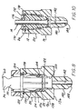
- the spool 12 carrying centering collar 170 and the tube 14, as described above, is then inserted into the first, second, and third stepped bores 120, 124, and 128 in the housing 20 of the female connector 16 as shown in Fig. 10.
- the spool 12 is inserted into the bores in the housing 20 a sufficient distance until the radially outward extending flange 115 on the top hat 24 snaps into the first groove 130 in third stepped 128 in the housing 20.
- the tapered portion 162 of the spool 12 will eventually engage the inner surface of the retaining ring 26 which is loosely disposed in the second groove 132 in the housing 20.
- the outward tapering surface of the tapered portion 162 causes the spaced ends of the retaining ring 26 to expand radially outward allowing passage of the large diameter end of the tapered portion 162 past the retaining ring 26.
- the retaining ring 26 snaps under spring force over the end shoulder 162 in the spool 12 into contact with the exterior surface 175 of the end flange 172 on the centering collar 170.
- the diameter of the exterior surface 175 of the centering collar 170 is selected such that the retaining collar 26 remains under spring force and is concentric with the longitudinal axis of the spool 12 and the tube 14. This creates a complete 360° shear surface between the retaining ring 26 and the spool 12 to distribute forces on the spool 12 evenly about the circumference of the spool 12 to securely retain the spool 12 in the housing 20 of the female connector 16.
- the centering collar 170 When it is necessary to service the quick connector of the present invention or the components connected to the tube 14 and/or the female connector 16, the centering collar 170 is popped out of the end of the housing 20. With the centering collar 170 removed from the end of the bore in the housing 20, the retaining ring 26 can be pulled out of the second groove 132 thereby enabling the entire spool 12 to be removed from the stepped bores in the housing 20.
- a new stuffer pin 30, preassembled with the O-ring 22, 24, top hat 24, retaining ring 26, retainer collar 90, and centering collar 170, and a new spool 12, may be employed to mount the seal elements 22 and 24 in the retaining ring 26 on the housing 20 of the female connector 16 as Well as permitting the spool body 12 and the new centering collar 170 to be snap mounted in the stepped bore of the housing 20 by the retaining ring 26 in the same manner as described above.
- the quick connector of the present invention also provides a simple push-in, snap connection between the spool and the female connector. This provides an advantageous low insertion force; while still having the requisite high pullout force resistance required for high fluid pressure applications.
- the unique centering collar maintains the retainer ring or clip centered about the end of the spool thereby creating a complete 360° shear surface distributing connection forces equally about the circumference of the spool and the retainer ring.
- the largest diameter of the tapered portion of the spool body is greater than the nominal inside diameter of the retaining clip in a relaxed position.
Landscapes
- Engineering & Computer Science (AREA)
- Mechanical Engineering (AREA)
- General Engineering & Computer Science (AREA)
- Transportation (AREA)
- Quick-Acting Or Multi-Walled Pipe Joints (AREA)
Claims (10)
- Raccord rapide (10) destiné à être utilisé avec un conduit (14), comprenant :un premier connecteur (16) ayant un perçage (120) s'étendant à travers lui-même et une première gorge annulaire (132) s'ouvrant depuis le perçage et espacée d'une extrémité du premier connecteur ;un second connecteur (12) qui inclut un noyau ayant un perçage (152) s'étendant à travers lui-même, une extrémité d'un conduit monté dans le perçage dans le noyau et établissant un trajet d'écoulement de fluide dans le second connecteur ;au moins un élément formant joint (22, 24) monté dans le perçage dans le premier connecteur et réalisant un joint entre le perçage (120) dans le premier connecteur et le noyau (12) ;une bague de retenue (26) disposée dans la première gorge (132) dans le premier connecteur, la bague de retenue ayant une ouverture traversante, la bague de retenue étant radialement expansible en introduisant le noyau (12) à travers elle-même de manière à monter le noyau par encliquetage dans le perçage dans le premier connecteur lors de l'introduction du noyau à une position totalement introduite dans le perçage dans le premier connecteur ; et caractérisé par :un collier annulaire (170) porté par le noyau (12) et monté de façon amovible sur le noyau de manière à maintenir un axe central du collier annulaire (170) coaxial avec un axe longitudinal du noyau, ledit collier étant positionné entre le noyau (12) et la bague de retenue (26) pour centrer la bague de retenue par rapport audit axe longitudinal du noyau.
- Raccord rapide (10) selon la revendication 1, comprenant encore :des moyens (168), portés sur le collier et sur le noyau, pour monter le collier sur le noyau.
- Raccord rapide (10) selon la revendication 1, dans lequel :le collier (170) a une surface extérieure circulaire (175) susceptible d'être engagée avec la bague de retenue pour centrer la bague de retenue par rapport à l'axe longitudinal à travers le noyau.
- Raccord rapide (10) selon la revendication 1, comprenant encore :une seconde gorge (130) formée dans le premier connecteur (16) et s'ouvrant vers le perçage (120) dans le premier connecteur ;l'élément formant joint incluant un premier joint (24) ayant une bride s'étendant radialement vers l'extérieur (115), la bride s'étendant radialement vers l'extérieur pouvant être engagée avec la seconde gorge pour monter le premier joint dans une position fixe à l'intérieur du perçage dans le premier connecteur.
- Raccord rapide (10) selon la revendication 4, dans lequel l'élément formant joint comprend encore :un second joint élastique (22) interposé entre le premier joint (24) et une extrémité du perçage (122) dans le premier connecteur.
- Procédé pour assembler un raccord rapide (10) formé d'un boîtier (20) ayant un perçage traversant (120), un noyau (12) portant un tube (14) ayant un perçage traversant, au moins un élément formant joint (22, 24) et une bague de retenue (26), le procédé comprenant les étapes consistant à :pré-monter l'élément formant joint (22, 24) dans le perçage, et la bague de retenue (26) dans une première gorge annulaire s'ouvrant depuis le perçage (120) dans le boîtier ; etmonter par encliquetage le noyau (12) dans le perçage dans le boîtier ;centrer la bague de retenue (26) par rapport à un axe longitudinal s'étendant à travers le noyau quand le noyau est totalement introduit dans le perçage dans le boîtier ; caractérisé par les étapes suivantes :prévoir un collier (170) ayant une surface extérieure circulaire (175) ;monter le collier (170) de façon amovible par-dessus le noyau (12) de telle façon que la surface extérieure du collier engage la bague de retenue pour centrer concentriquement la bague de retenue par rapport à un axe longitudinal à travers le perçage dans le noyau.
- Procédé selon la revendication 6, dans lequel les étapes de montage par encliquetage comprennent :de doter le noyau (12) d'une surface en rétrécissement vers l'extérieur (162) pour faire dilater la bague de retenue (26) depuis un diamètre nominal jusqu'à un diamètre dilaté pendant l'introduction du noyau à travers la bague de retenue pour permettre à la bague de retenue de s'encliqueter derrière une extrémité du noyau (12) lors de l'introduction totale du noyau.
- Procédé selon la revendication 6, dans lesquels l'étape consistant à pré-monter le joint (22, 24) et la bague de retenue (26) dans le perçage dans le boîtier comprend les étapes consistant à :monter la bague de retenue (26) dans un manchon conique ayant des parois latérales en rétrécissement vers l'intérieur qui convergent depuis une première extrémité dans laquelle la bague de retenue est initialement montée vers une seconde extrémité opposée ;prévoir une tige de poussée allongée (30) ;monter un collier de retenue sur une extrémité de la tige de poussée, le collier de retenue ayant une bride annulaire avec un diamètre intérieur égal à un diamètre de la seconde extrémité du manchon ;repousser la bague de retenue depuis la première extrémité vers la seconde extrémité du manchon pour comprimer la bague de retenue alors que l'on laisse coulisser la bague de retenue et la tige de poussée l'une par rapport à l'autre pour monter par compression la bague de retenue autour de la tige de poussée ;monter ledit élément formant joint sur la tige de poussée en étant espacé de la bague de retenue ;faire coulisser la tige de poussée (30) dans le perçage dans le boîtier ;fixer ledit élément formant joint (22) dans une position prédéterminée à l'intérieur du perçage du boîtier ;engager la bague de retenue dans une gorge annulaire s'ouvrant vers le perçage dans le boîtier, dans laquelle la bague de retenue se dilate radialement vers l'extérieur depuis un état comprimé ; etdégager la tige de poussée depuis l'élément formant joint et la bague de retenue montée dans le perçage dans le boîtier.
- Procédé selon la revendication 6, comprenant encore l'étape consistant à:monter un autre élément formant joint (24) autour de la tige de poussée à proximité dudit élément formant joint (22).
- Procédé selon la revendication 6, dans lequel l'étape consistant à fixer ledit élément formant joint comprend encore les étapes consistant à :prévoir une autre gorge annulaire dans le perçage dans le boîtier et s'ouvrant vers le perçage dans le boîtier ;doter ledit élément formant joint d'une bride s'étendant radialement vers l'extérieur et engageable par encliquetage avec l'autre gorge pour fixer ledit élément formant joint dans une position prédéterminée à l'intérieur du perçage dans le boîtier.
Applications Claiming Priority (2)
| Application Number | Priority Date | Filing Date | Title |
|---|---|---|---|
| US457210 | 1999-12-08 | ||
| US09/457,210 US6378908B1 (en) | 1999-12-08 | 1999-12-08 | High pressure quick connector |
Publications (2)
| Publication Number | Publication Date |
|---|---|
| EP1106897A1 EP1106897A1 (fr) | 2001-06-13 |
| EP1106897B1 true EP1106897B1 (fr) | 2005-09-21 |
Family
ID=23815849
Family Applications (1)
| Application Number | Title | Priority Date | Filing Date |
|---|---|---|---|
| EP00126645A Expired - Lifetime EP1106897B1 (fr) | 1999-12-08 | 2000-12-04 | Raccord rapide haute pression et procédé d'assemblage |
Country Status (4)
| Country | Link |
|---|---|
| US (1) | US6378908B1 (fr) |
| EP (1) | EP1106897B1 (fr) |
| JP (1) | JP3842547B2 (fr) |
| DE (1) | DE60022725T2 (fr) |
Families Citing this family (13)
| Publication number | Priority date | Publication date | Assignee | Title |
|---|---|---|---|---|
| TW200602577A (en) * | 2004-04-22 | 2006-01-16 | Swagelok Co | Fitting for tube and pipe |
| DE112007000909A5 (de) * | 2006-05-01 | 2009-01-15 | Luk Lamellen Und Kupplungsbau Beteiligungs Kg | Freilauf mit Dämpfung |
| US7581760B2 (en) * | 2006-05-31 | 2009-09-01 | Yh America, Inc. | Hose coupling endform for fluid transfer assemblies |
| US7581761B2 (en) * | 2006-06-01 | 2009-09-01 | Yh America, Inc. | Asymmetric hose coupling endform for fluid transfer assemblies |
| JP2010509548A (ja) | 2006-11-02 | 2010-03-25 | スウエイジロク・カンパニー | トルクによって締め付けられる継手 |
| US7837041B2 (en) * | 2007-06-27 | 2010-11-23 | Yh America, Inc. | Method of determining the robustness of endformed tubular assembly and predicting the performance of such assembly in high pressure applications |
| US7819436B2 (en) * | 2007-06-27 | 2010-10-26 | Yh America, Inc. | Endformed tubular assembly |
| US7870655B2 (en) * | 2007-06-27 | 2011-01-18 | Yh America, Inc. | Process of endforming a tubular assembly |
| JP2010535989A (ja) | 2007-08-03 | 2010-11-25 | スウエイジロク・カンパニー | トルクによる引き上げフェルール継手 |
| DE102012102256B4 (de) | 2012-03-16 | 2024-05-29 | Endress+Hauser Conducta Gmbh+Co. Kg | Analysegerät mit Basismodul und austauschbarer Kassette |
| US10781958B2 (en) * | 2017-10-31 | 2020-09-22 | Oetiker Ny, Inc. | Low peak insertion tube end form |
| EP3736481B1 (fr) * | 2019-05-07 | 2022-01-19 | A. Raymond et Cie | Ensemble connecteur rapide avec languette de vérification |
| EP4279347A1 (fr) * | 2022-05-17 | 2023-11-22 | Arfesan Arkan Fren Elemanlari Sanayi Ve Ticaret A.S. | Appareil de connexion d'air |
Family Cites Families (20)
| Publication number | Priority date | Publication date | Assignee | Title |
|---|---|---|---|---|
| US2521127A (en) * | 1948-05-08 | 1950-09-05 | Wright Aeronautical Corp | Fluid tight joint |
| US3404904A (en) * | 1966-01-17 | 1968-10-08 | Holmberg Inc | Pipe couplings |
| FR2283381A1 (fr) * | 1974-03-15 | 1976-03-26 | Sogemo Automatisation | Perfectionnements apportes aux systemes de raccordement pour conduits, notamment pour tubes plastiques semi-rigides |
| US3944263A (en) * | 1975-03-14 | 1976-03-16 | Hydrotech International, Inc. | Dynamic pipe coupling |
| DE2824943C2 (de) | 1978-06-07 | 1986-07-31 | Armaturenfabrik Hermann Voss GmbH + Co, 5272 Wipperfürth | Anschlußvorrichtung für Bremsleitungen |
| US4915136A (en) | 1980-10-29 | 1990-04-10 | Proprietary Technology, Inc. | Stuffer plug quick connector assembly |
| JPS59150087U (ja) * | 1983-03-26 | 1984-10-06 | 千代田通商株式会社 | ホ−スの継手 |
| US4884829A (en) | 1986-09-16 | 1989-12-05 | Johannes Schaefer Vorm. Stettiner Schraubenwerke Gmbh & Co. Kg | Plug-in connection for connecting tube and host lines in particular for use in tube-line systems of motor vehicles |
| DE3806404C2 (de) * | 1988-02-29 | 1994-06-09 | Raymond A Gmbh & Co Kg | Lösbare Steckverbindung für halbstarre Rohre |
| IT1216491B (it) * | 1988-03-22 | 1990-03-08 | Finimpresa Spa | Raccordo di collegamento rapido per tubi flessibili con anello conico di trattenuta. |
| US5538297A (en) | 1991-09-10 | 1996-07-23 | Bundy Corporation | Quick connect tubing connector |
| US5297818A (en) | 1991-12-18 | 1994-03-29 | Itt Corporation | Retainer for pop-top indicator |
| US5374089A (en) | 1992-09-29 | 1994-12-20 | Itt Industries Inc. | High pressure quick connector |
| US5472016A (en) | 1993-10-04 | 1995-12-05 | Itt Corporation | Quick connector stuffer pin |
| US5486025A (en) | 1994-09-29 | 1996-01-23 | Bundy Corporation | Stuffer pin assembly for quick connector |
| US5711549A (en) | 1995-06-07 | 1998-01-27 | Itt Automotive, Inc. | High pressure quick connect for use in automotive brake system application |
| GB9615394D0 (en) | 1996-07-23 | 1996-09-04 | Rolls Royce Plc | Gas turbine engine rotor disc with cooling fluid passage |
| US6073973A (en) * | 1996-10-31 | 2000-06-13 | Stanley Aviation Corporation | Lightweight positive lock coupling |
| US5882049A (en) * | 1996-12-18 | 1999-03-16 | Itt Automotive, Inc. | High pressure quick connect with reduced volumetric displacement and piloted snap ring |
| EP0905431A3 (fr) * | 1997-09-30 | 1999-09-15 | Aeroquip-Vickers International GmbH | Dispositif de raccordement |
-
1999
- 1999-12-08 US US09/457,210 patent/US6378908B1/en not_active Expired - Fee Related
-
2000
- 2000-12-04 DE DE60022725T patent/DE60022725T2/de not_active Expired - Lifetime
- 2000-12-04 EP EP00126645A patent/EP1106897B1/fr not_active Expired - Lifetime
- 2000-12-08 JP JP2000374421A patent/JP3842547B2/ja not_active Expired - Lifetime
Also Published As
| Publication number | Publication date |
|---|---|
| EP1106897A1 (fr) | 2001-06-13 |
| JP2001200973A (ja) | 2001-07-27 |
| DE60022725D1 (de) | 2005-10-27 |
| JP3842547B2 (ja) | 2006-11-08 |
| DE60022725T2 (de) | 2006-06-22 |
| US6378908B1 (en) | 2002-04-30 |
Similar Documents
| Publication | Publication Date | Title |
|---|---|---|
| US7467813B2 (en) | Quick connector | |
| US5897142A (en) | Push-to-release quick connector | |
| US5511830A (en) | Quick connect tube couplings | |
| US7891380B2 (en) | Protective cap for quick connector | |
| US4948175A (en) | Swivelable quick connector assembly | |
| EP0659126B1 (fr) | Raccord rapide a collier coulissant | |
| US4601497A (en) | Swivelable quick connector assembly | |
| EP1106897B1 (fr) | Raccord rapide haute pression et procédé d'assemblage | |
| US5711549A (en) | High pressure quick connect for use in automotive brake system application | |
| JPH09506152A (ja) | 長細バーブ・デザインを有する迅速コネクタ・ハウジング | |
| WO1996018842A1 (fr) | Raccord rapide a liberation par pression a retenue par encliquetage | |
| JPH09503574A (ja) | 一体のリリース部材を有するクイックコネクタ | |
| US6234544B1 (en) | Quick connector with confirmation feature | |
| US5775738A (en) | Means of coupling of non-threaded connections | |
| US5927761A (en) | Means of coupling of non-threaded connections | |
| US7891710B2 (en) | Connector with release mechanism, and method for forming a releasable fluid connection | |
| US7857360B2 (en) | Snap-in-place valved coupler | |
| EP0660907B1 (fr) | Ensemble tubulaire et son procede de fabrication | |
| US6412826B1 (en) | High pressure quick connector | |
| US20030001384A1 (en) | Seal cap and connector assembly | |
| US6086113A (en) | Means of coupling of non-threaded connections | |
| EP0852682A1 (fr) | Raccord instantane a confirmation de position | |
| WO2023101701A1 (fr) | Ensemble de raccordement fluidique doté de support d'élément de retenue | |
| MXPA98002365A (en) | Fast connector with confirmac features | |
| CA2232856A1 (fr) | Raccord instantane a confirmation de position |
Legal Events
| Date | Code | Title | Description |
|---|---|---|---|
| PUAI | Public reference made under article 153(3) epc to a published international application that has entered the european phase |
Free format text: ORIGINAL CODE: 0009012 |
|
| AK | Designated contracting states |
Kind code of ref document: A1 Designated state(s): DE FR GB |
|
| AX | Request for extension of the european patent |
Free format text: AL;LT;LV;MK;RO;SI |
|
| 17P | Request for examination filed |
Effective date: 20011213 |
|
| AKX | Designation fees paid |
Free format text: DE FR GB |
|
| 17Q | First examination report despatched |
Effective date: 20040512 |
|
| GRAP | Despatch of communication of intention to grant a patent |
Free format text: ORIGINAL CODE: EPIDOSNIGR1 |
|
| GRAS | Grant fee paid |
Free format text: ORIGINAL CODE: EPIDOSNIGR3 |
|
| GRAA | (expected) grant |
Free format text: ORIGINAL CODE: 0009210 |
|
| AK | Designated contracting states |
Kind code of ref document: B1 Designated state(s): DE FR GB |
|
| REG | Reference to a national code |
Ref country code: GB Ref legal event code: FG4D |
|
| REF | Corresponds to: |
Ref document number: 60022725 Country of ref document: DE Date of ref document: 20051027 Kind code of ref document: P |
|
| ET | Fr: translation filed | ||
| PLBE | No opposition filed within time limit |
Free format text: ORIGINAL CODE: 0009261 |
|
| STAA | Information on the status of an ep patent application or granted ep patent |
Free format text: STATUS: NO OPPOSITION FILED WITHIN TIME LIMIT |
|
| 26N | No opposition filed |
Effective date: 20060622 |
|
| REG | Reference to a national code |
Ref country code: FR Ref legal event code: PLFP Year of fee payment: 16 |
|
| REG | Reference to a national code |
Ref country code: FR Ref legal event code: PLFP Year of fee payment: 17 |
|
| REG | Reference to a national code |
Ref country code: FR Ref legal event code: PLFP Year of fee payment: 18 |
|
| PGFP | Annual fee paid to national office [announced via postgrant information from national office to epo] |
Ref country code: FR Payment date: 20191226 Year of fee payment: 20 |
|
| PGFP | Annual fee paid to national office [announced via postgrant information from national office to epo] |
Ref country code: DE Payment date: 20191231 Year of fee payment: 20 Ref country code: GB Payment date: 20200102 Year of fee payment: 20 |
|
| REG | Reference to a national code |
Ref country code: DE Ref legal event code: R071 Ref document number: 60022725 Country of ref document: DE |
|
| REG | Reference to a national code |
Ref country code: GB Ref legal event code: PE20 Expiry date: 20201203 |
|
| PG25 | Lapsed in a contracting state [announced via postgrant information from national office to epo] |
Ref country code: GB Free format text: LAPSE BECAUSE OF EXPIRATION OF PROTECTION Effective date: 20201203 |