EP1106897B1 - High pressure quick connector and method of assembly - Google Patents
High pressure quick connector and method of assembly Download PDFInfo
- Publication number
- EP1106897B1 EP1106897B1 EP00126645A EP00126645A EP1106897B1 EP 1106897 B1 EP1106897 B1 EP 1106897B1 EP 00126645 A EP00126645 A EP 00126645A EP 00126645 A EP00126645 A EP 00126645A EP 1106897 B1 EP1106897 B1 EP 1106897B1
- Authority
- EP
- European Patent Office
- Prior art keywords
- spool
- bore
- retaining ring
- connector
- housing
- Prior art date
- Legal status (The legal status is an assumption and is not a legal conclusion. Google has not performed a legal analysis and makes no representation as to the accuracy of the status listed.)
- Expired - Lifetime
Links
Images


Classifications
-
- F—MECHANICAL ENGINEERING; LIGHTING; HEATING; WEAPONS; BLASTING
- F16—ENGINEERING ELEMENTS AND UNITS; GENERAL MEASURES FOR PRODUCING AND MAINTAINING EFFECTIVE FUNCTIONING OF MACHINES OR INSTALLATIONS; THERMAL INSULATION IN GENERAL
- F16L—PIPES; JOINTS OR FITTINGS FOR PIPES; SUPPORTS FOR PIPES, CABLES OR PROTECTIVE TUBING; MEANS FOR THERMAL INSULATION IN GENERAL
- F16L37/00—Couplings of the quick-acting type
- F16L37/08—Couplings of the quick-acting type in which the connection between abutting or axially overlapping ends is maintained by locking members
- F16L37/084—Couplings of the quick-acting type in which the connection between abutting or axially overlapping ends is maintained by locking members combined with automatic locking
- F16L37/088—Couplings of the quick-acting type in which the connection between abutting or axially overlapping ends is maintained by locking members combined with automatic locking by means of a split elastic ring
-
- B—PERFORMING OPERATIONS; TRANSPORTING
- B60—VEHICLES IN GENERAL
- B60T—VEHICLE BRAKE CONTROL SYSTEMS OR PARTS THEREOF; BRAKE CONTROL SYSTEMS OR PARTS THEREOF, IN GENERAL; ARRANGEMENT OF BRAKING ELEMENTS ON VEHICLES IN GENERAL; PORTABLE DEVICES FOR PREVENTING UNWANTED MOVEMENT OF VEHICLES; VEHICLE MODIFICATIONS TO FACILITATE COOLING OF BRAKES
- B60T17/00—Component parts, details, or accessories of power brake systems not covered by groups B60T8/00, B60T13/00 or B60T15/00, or presenting other characteristic features
- B60T17/04—Arrangements of piping, valves in the piping, e.g. cut-off valves, couplings or air hoses
- B60T17/043—Brake line couplings, air hoses and stopcocks
Definitions
- the present invention relates, in general, to high pressure quick connectors employed in fluid conduit systems.
- Snap fit or quick connectors have been found to be useful in a wide range of applications. In particular, they are frequently employed for joining fluid carrying conduits in automotive and industrial applications. Such connectors have found general acceptance as they are typically capable of being closed in a single uni-axial movement which facilitates automated assembly, and entail simple designs which are relatively inexpensive to produce.
- a further advantage of quick connect fittings is that they provide an effective seal for handling volatile or hazardous fluids, such as gasoline, while permitting ease of disassembly and reassembly during repair of a host system.
- connection means For many high pressure applications, such as with brake lines, threaded fittings are used as connection means. If not aligned correctly, cross threading may result. If excessive torque is applied, over threading may result. As a result of cross-threading or overthreading, the threads are stripped and the fittings must be scrapped and replaced.
- the brake lines are connected to a brake manifold or junction during the assembly process of the vehicle.
- the threaded connections of the prior art are located close together which increases assembly time and labor as well as the potential for error.
- a further disadvantage typical of prior art high pressure quick connectors is that they must be assembled with an associated tube and shipped to a final destination as a single assembly. Such shipment is expensive and subjects the connectors to damage from mishandling.
- US Patent 5,7118,459 describes a high pressure quick connector especially for use in connection with brake lines of a vehicle, having a housing that selectively receives a tube retainer cap with retaining means such a a garter spring or snap ring allow for a low insertion force but high pull-off forces.
- a release tool is required to free the snap ring from blocking shoulders of the cap by extending it into a housing groove.
- the present invention is a high pressure quick connector according to claim 1 and method of assembling the quick connector according to claim 6 with is usable in interconnecting fluid conduits or elements in a high pressure fluid system.
- the collar may be mounted on the spool by means carried on the collar and the spool.
- such means comprises an interlocking projection and groove.
- another groove is formed in the first connector and opens to the bore in the first connector.
- At least one of the seal elements has a radially outward extending flange which engages the another groove to mount the seal element in a fixed position within the bore and the first connector.
- the seal element comprises a resilient seal and a top hat seal elements.
- the method of the present invention also defines the step of snap mounting the spool in the housing as including the step of providing the spool with an outwardly tapered surface of expanding the retaining ring from a nominal diameter to an expanded diameter during insertion of the spool through the retaining ring to permit the retaining ring to snap behind an end of the spool upon full insertion of the spool into the bore in the housing.
- the step of remounting the seal and retainer ring in the bore in the housing comprises the steps of:
- the method of the present invention further comprises mounting a second seal on the stuffer pin adjacent to the first seal.
- the quick connector constructed in accordance with the present invention overcomes many of the problems encountered with the previously devised quick connectors for use in fluid systems, particularly high pressure quick connectors.
- the present quick connector provides a low insertion force, retention at operating pressure, the ability to be easily removed for service as well as the ability to transport the quick connector from the initial manufacturer to the final user without damage to the various quick connector components.
- the unique step of premounting the seal elements and the retainer ring within the bore and the housing prevents damage to such components which were previously transported to the use site by means of mounting on the exterior surface of the spool.
- the present invention uniquely prevents damage to the seal element and the retainer ring as well as any inadvertent loss or separation of the seal element and retainer ring from the quick connector.
- the quick connector of the present invention is also easily connected in a snap-together connector between the spool and the female connector at a low insertion force.
- the unique centering of the retaining ring about a longitudinal axis extending through the spool centers the retention forces on the spool and provides a complete 360 shear surface about the spool to firmly retain the spool within the female connector.
- a quick connector 10 including a male connector or spool assembly 12 adapted for connecting a tube or conduit 14, such as a brake line tube, to another component, such as a female connector 16.
- the female connector 16 may have any applicable exterior configuration depending upon the application.
- Fig. 1 depicts the female connector 16 in the form of a housing 20 for receiving an in-line brake tube 14.
- the housing 20, as described hereafter and shown in greater detail in Figs. 8-10, has an internal bore or, more preferably, a pair of axially aligned stepped bores which receive at least one seal element, such as an 0-ring 22, a top hat 24, the spool 12, a spring retainer ring or clip 26, and a centering collar 28.
- the external configuration of the housing 20 may change relative to the application.
- brake lines may be connected to a housing in the form of a brake manifold or junction having multiple receiving bores therein.
- the male connector or spool 12 in the housing 20 is not limited to anti-lock brake systems, but may also be used for any high pressure fluid connection.
- a stuffer pin 30 is provided for initially mounting the O-ring 22, the top hat 24 and the retaining 26 within the internal stepped bore of the housing 20. This enables such components to be premounted within the housing 20 and protected from damage during shipment from the quick connector manufacturer to the final assembly location.
- the spool or male connector 12 is merely inserted into the housing 20 in a snap-in connection to complete the fluid connection between the tube 14 and the bore extending through the housing 20.
- the stuffer pin 30 is in the form of a one-piece body, preferably formed of a suitable plastic material.
- the stuffer pin 30 includes a shaft 32, a stop 34, and a handle 36.
- the shaft 32 has a tubular elongated shape which may be formed of a single member or, as described in greater detail in U.S. Patent No. 5,472,016, the entire contents of which are incorporated herein by reference, with at least two and preferably four perpendicularly oriented legs, such as opposed legs 38 and 40 are spaced 90° from adjacent legs and are integrally joined to each other along a common center edge extending along the length of the shaft 32. It will be understood that the shaft 32 may have other shapes, such as a generally solid, cylindrical shape with a smooth outer surface.
- the shaft 32 is integrally joined to the stop 34 at a first end.
- a second end 42 of the shaft 32 extends axially from the first end and the stop 34.
- At least one and, preferably, a plurality of resilient arms 44 are integrally formed on and extend axial outward from the second end 42 of the shaft 32.
- a minimum of two diametrically opposed arms 44 and, preferably, four equally-circumferentially spaced arms 44 are formed on and extend outward from the second end 42 of the shaft 32.
- Each of the arms 44 is formed with a narrow cross section portion extending from the second end 42 so as to be able to resiliently bend or flex inwardly upon mounting of the O-ring 22 and top hat 24 thereover.
- each arm 44 has a generally planar inner side wall which is parallel to the longitudinal axis of the shaft 32.
- the radially outermost surface of each arm 44 has a maximum diameter outer edge 46 which is formed on a second side wall of each arm 44 which is formed of a first inclined surface 48 extending from the second end 42 of the shaft 32 and a second declining outer edge 50 which extends to the outer surface 50 which extends to the outer end of each arm 44.
- Seal mounting means are formed on the shaft 32.
- the seal mounting means comprises an annular recess 52 which extends radially inward between the outermost edge 46 of each arm 44 and a radially enlarged central portion of the shaft 32.
- the recess 52 cooperates with the outer edge 46 of each arm 44 to define an area for receiving and maintaining at least one seal element, such as the O-ring 22 and the top hat 24 in a mounted position on the stuffer pin 30 prior to assembly into the female connector 16.
- the stop 34 is the form of a circular disc or flange and has an outer edge with a outer diameter slightly larger than the outer diameter of the enlarged central portion of the shaft 32.
- the stop 34 has opposed first and second surfaces 54 and 56 which are in the form of an annulus and project radially outwary from the outer surfaces of the adjoining portions of the shaft 32 and the handle 36, respectively.
- a reduced diameter annular notch 58 is formed on the exterior surface of the shaft 32 between the enlarged central portion of the shaft 32 and the first surface 54 of the stop 34.
- the notch 58 forms a retaining ring mounting surface in conjunction with the first surface 54 of the stop 34 as described hereafter.
- the handle 36 extends from the stop 34 generally coaxial with the longitudinal axis of the shaft 32.
- the handle 36 terminates in a flat end portion 60 adjacent to a pair of opposed notches 62 and facilitates manual insertion and withdrawal of the stuffer pin 30 during assembly of the various components thereon as described hereafter.
- the initial step is to mount the retaining ring 26 on the stuffer pin 30.
- the retaining ring 26 may be a generally planar ring having a hollow interior opening or aperture 64.
- a spiral retaining ring manufactured by Smalley as model no. WHM-62-S02 may be employed.
- the annular ring portion of the retaining ring 26 is split such that two ends are spaced apart to permit radial expansion and contraction of the retaining ring 26 as described hereafter.
- the retaining ring 26 is inserted into a sleeve 66 having an interior through bore 68 extending between a first end 70 and an opposed second end 72.
- a first side wall portion 74 of the sleeve 66 tapers from a first smaller diameter at the first end 70 to a larger diameter 76 before flaring outward to form a skirt 78 of even larger diameter which extends to the second end 72.
- the retaining ring 26 in its expanded position is inserted into the interior bore 68 in sleeve 66 until the retaining ring 26 snugly engages the inward tapering surfaces of the first side wall portion 74 of the sleeve 66 at the first diameter 76.
- a pusher 80 is provided for urging the retaining ring 26 over the stuffer pin 30 as described hereafter.
- the pusher 80 is in the form of a hollow tubular cylindrical member having an interior bore 82 extending between opposed first and second ends 84 and 86.
- the first end 84 of the pusher 80 is provided with an inner diameter so as to engage the retaining ring 26 as the sleeve 66 and the pusher 80 are telescopingly engaged so as to slide the retaining ring 26 from the initial mounting position shown in Fig. 3 upward toward the first end 70 of the sleeve 66.
- the retainer collar 90 formed of a suitable plastic, has a bottle-top configuration formed of a planar end portion 92 with a central aperture 94 and a depending annular flange or skirt 96 depending from the outer periphery of the planar portion 92.
- the aperture 94 is sized to slidably receive the handle 36 of the stuffer pin 30; but is smaller in diameter than the diameter of the stop 34 to prevent the stuffer 30 from sliding through the aperture 94 in the retainer collar 90 past the stop 34.
- the radially inner end of the skirt 96 has a tapered, depending edge to center the retainer collar 90 on the sleeve 66.
- the retainer collar 90 is in turn supported against a shoulder 98 formed at one end of a holder 100.
- the holder 100 has an internal bore 102 projecting from a first end 104 to the shoulder 98.
- the outer side wall of the holder 100 which is also formed of a suitable plastic material, terminates in an annular radially extending flange which turns into an axial flange 106 extending generally parallel to the side wall 101.
- the shoulder 98 forms a seat for the collar 90.
- the stuffer pin 30 is initially inserted arms 44 first into the hollow end portion of the sleeve 90 with the handle 36 of the stuffer pin 30 projecting through the aperture 94 in the sleeve 90 into the bore 102 in the holder 100.
- the joined stuffer pin 30, retainer collar 90, and holder 100 as well as the sleeve 66 and the pusher 80 are then urged together to the position shown in Fig. 4 until the end of the retainer collar 90 abuts the end 70 of the sleeve 66. In this position, the first end 84 of the pusher 80 engages the retaining ring 26 mounted within the sleeve 66.
- the pusher 80 urges the retaining ring 26 along the inner surface 68 of the inward tapering first side wall portion 74 of the sleeve 66, the spaced ends of the retaining ring 26 are compressed or urged together thereby compressing the retaining ring 26 into a smallest diameter until the retaining ring 26 reaches the smallest diameter shown in Figs. 6 and 7 wherein the retainer ring 26 is positioned within the retainer collar 90.
- the pusher 80, the sleeve 66, and the holder 100 are then disengaged from the retaining collar 90 and the retainer ring 26 leaving the stuffer pin 30 held within the bore formed within the retainer collar 90 by the axially extending flange 96 by the compressed retaining ring 26, as shown in Fig. 7.
- the stop 34 on the stuffer pin 30 is sandwiched between the inward tending portion of the planar end 92 of the retainer collar 90 and the compressed retaining ring 26.
- the top hat 24 which is formed with an annular ring portion 110 and a pair of axially extending legs 112 and 114, is then mounted over the arms 44 on the stuffer pin 30 by bending the outer edge portion 46 of the arms 44 inward until the inner diameter of the bore through the ring portion 110 of the top hat 24 passes thereover enabling the top hat 24 to be slid along the recess 52 until an inward conical seat 116 formed between the ring portion 110 and the legs 112 and 114 engages a mating conical seat 118 formed on the stuffer pin 30 between the recess 52 and the enlarged diameter portion of the shaft 32.
- the seal element 22, such as an 0-ring or multi-lip seal is then urged over the arms 44 and seated in the recess 52 between the ring portion 110 of the top hat 24 and the first inclined surface 48 of each arm 44 on the stuffer pin 30.
- the stuffer pin 30 carrying the top hat 24 and the 0-ring 22, and the retaining ring 26 in the retainer collar 90 is now ready for insertion into the female connector 16 as shown in Fig. 8.
- the housing 20 of the female connector 16 is formed with a first stepped bore 120 of a first diameter.
- a shoulder 122 is formed at one end of the first stepped bore 120 and extends radially outward from the inner surface of the first bore 120 and merges into a second stepped bore 124 of a second, larger diameter.
- An outward inclined, generally conical surface 126 is formed at one end of the second bore 124 and extends radially outward to form a third stepped bore 128 of a third diameter.
- a first annular groove 130 is formed in the third stepped bore 128 between opposite ends thereof.
- a second annular groove 132 is formed in the third stepped bore 128 adjacent one end 134 of the housing 20.
- An opposed second end 136 is formed adjacent an enlarged diameter end portion of the housing 20.
- the enlarged diameter end portion 138 is formed with a plurality of hex flats.
- an elongated tubular shank 140 projects from the second end 136 of the housing 20.
- a bore 142 extends through the shank 140 to an exterior end 144 of the shank 140.
- the bore 142 is disposed in fluid communication with the first stepped bore 120 in the housing 20.
- External threads may be formed on the shank 140 for mounting the shank 140 and the entire housing 20 in an external component, not shown.
- the shank 140 may be formed with a smooth exterior surface and provided with an outer diameter for an interference fit in a bore in an external component.
- the entire housing 20, with or without the shank 140 may be integrally formed as a unitary part of another external component.
- the stuffer pin 30 With the stuffer pin 30 assembled as shown in Fig. 7, the stuffer pin 30 is inserted, arms 44 frontmost, into the open end of the third stepped bore 128 in the housing 20 of the female connector as shown in Fig. 8. The insertion of the stuffer pin 30 continues until the radially outward flange 115 on the top hat 24 snaps into the first groove 130 in the housing 20.
- the retainer ring 26 is disposed in line with to the second groove 132 in the housing 20 and expands radially outward into the second groove 132 bringing the outer portions of the retainer ring 26 into the second groove 132 thereby trapping the retainer ring 26 in the second groove 132. This halts further possible insertion of the stuffer pin 30 into the housing 20.
- the expanded O.D. of the retaining ring 26 is less than the O.D. of the second groove 132, allowing some sideways play or movement of the retaining ring 26 within the second groove 132.
- the stuffer pin 30 is then removed from the housing 20 by grasping the handle 36 and pulling the stuffer pin 30 axially away from the retainer ring 26.
- the enlarged outer edge 46 on the arms 44 of the stuffer pin 30 engage the O-ring 22 causing the arms 44 to bend radially inward permitting the arms 44 to pass through the narrow diameter bore in the O-ring 22 as well as the bore in the ring portion 110 of the top hat 24.
- the arms 44 bend inward when engaging the inner surfaces of the retaining ring 26 until the stuffer pin 30 is free of the housing 20.
- the I.D of the retaining ring 26, when in the expanding position is larger than the enlarged portion of the shaft 32 permitting the stuffer pin 30 to pass freely therethrough.
- the spool 12 is in the form of a tube retainer which positively engages a flared end or endform 150 at one end of the tube 14.
- the spool 12 is generally in the form of a cylindrical body having a through bore 152 extending between opposed ends.
- the bore 152 has a generally constant diameter cross section which merges at one end with a conical, radially outward extending seat 154.
- the conical surface or seat 154 is formed complementary in shape to a conical flange 156 on the tube endform 150 for positively attaching the spool 12 to the conduit or tube 14.
- one end 158 of the spool 12 is rolled over the end of the conical flange 156 at one end of the tube 14 to form a tight, metal-to-metal seal between the tube 14 and the spool 12.
- the body of the spool 12 tapers outwardly to a first constant diameter portion 160. Generally intermediate the opposed ends of the spool 12, the body tapers further outwardly at a first angle and then at a shallower angle to form a tapered portion 162 which extends to an end shoulder 164.
- a smaller diameter neck 166 projects centrally from the end shoulder 164.
- the neck 166 is concentric with the bore 152 and has an outwardly extending, annular flange 168 formed intermediately between the end of the neck 166 and the end shoulder 164.
- a centering collar 170 is mounted on the spool 12 generally in contact with the end shoulder 164 and the outer surface of the neck 166.
- the centering collar 170 which may be formed of a suitable plastic, has a generally annular end flange 172 and a smaller diameter center portion 174 projecting therefrom.
- a bore 176 extends through the end flange 172 and the center portion 174 for receiving the neck 166 of the spool 12 and the tube 14 therethrough as shown in Fig. 9.
- the center portion 174 has a generally circular outer surface 175 of a predetermined diameter.
- the collar 170 can also have an outer surface formed of a plurality of radially extending, equal length arms.
- An annular, inward opening groove 178 is formed in the center portion 174 of the centering collar 170 for snap connection to the flange 168 on the neck 166 of the spool 12 to mount the centering collar 170 on the spool 12.
- the spool 12 carrying centering collar 170 and the tube 14, as described above, is then inserted into the first, second, and third stepped bores 120, 124, and 128 in the housing 20 of the female connector 16 as shown in Fig. 10.
- the spool 12 is inserted into the bores in the housing 20 a sufficient distance until the radially outward extending flange 115 on the top hat 24 snaps into the first groove 130 in third stepped 128 in the housing 20.
- the tapered portion 162 of the spool 12 will eventually engage the inner surface of the retaining ring 26 which is loosely disposed in the second groove 132 in the housing 20.
- the outward tapering surface of the tapered portion 162 causes the spaced ends of the retaining ring 26 to expand radially outward allowing passage of the large diameter end of the tapered portion 162 past the retaining ring 26.
- the retaining ring 26 snaps under spring force over the end shoulder 162 in the spool 12 into contact with the exterior surface 175 of the end flange 172 on the centering collar 170.
- the diameter of the exterior surface 175 of the centering collar 170 is selected such that the retaining collar 26 remains under spring force and is concentric with the longitudinal axis of the spool 12 and the tube 14. This creates a complete 360° shear surface between the retaining ring 26 and the spool 12 to distribute forces on the spool 12 evenly about the circumference of the spool 12 to securely retain the spool 12 in the housing 20 of the female connector 16.
- the centering collar 170 When it is necessary to service the quick connector of the present invention or the components connected to the tube 14 and/or the female connector 16, the centering collar 170 is popped out of the end of the housing 20. With the centering collar 170 removed from the end of the bore in the housing 20, the retaining ring 26 can be pulled out of the second groove 132 thereby enabling the entire spool 12 to be removed from the stepped bores in the housing 20.
- a new stuffer pin 30, preassembled with the O-ring 22, 24, top hat 24, retaining ring 26, retainer collar 90, and centering collar 170, and a new spool 12, may be employed to mount the seal elements 22 and 24 in the retaining ring 26 on the housing 20 of the female connector 16 as Well as permitting the spool body 12 and the new centering collar 170 to be snap mounted in the stepped bore of the housing 20 by the retaining ring 26 in the same manner as described above.
- the quick connector of the present invention also provides a simple push-in, snap connection between the spool and the female connector. This provides an advantageous low insertion force; while still having the requisite high pullout force resistance required for high fluid pressure applications.
- the unique centering collar maintains the retainer ring or clip centered about the end of the spool thereby creating a complete 360° shear surface distributing connection forces equally about the circumference of the spool and the retainer ring.
- the largest diameter of the tapered portion of the spool body is greater than the nominal inside diameter of the retaining clip in a relaxed position.
Description
- The present invention relates, in general, to high pressure quick connectors employed in fluid conduit systems.
- Snap fit or quick connectors have been found to be useful in a wide range of applications. In particular, they are frequently employed for joining fluid carrying conduits in automotive and industrial applications. Such connectors have found general acceptance as they are typically capable of being closed in a single uni-axial movement which facilitates automated assembly, and entail simple designs which are relatively inexpensive to produce.
- A further advantage of quick connect fittings is that they provide an effective seal for handling volatile or hazardous fluids, such as gasoline, while permitting ease of disassembly and reassembly during repair of a host system.
- In applications where hazardous material is to flow through a fitting, for example, in vehicle brake lines, prevention of inadvertent release of the quick connector is of primary concern. Accordingly, relatively high axial pull apart strength specifications are mandated. In addition, low insertion forces are required.
- Currently, for many high pressure applications, such as with brake lines, threaded fittings are used as connection means. If not aligned correctly, cross threading may result. If excessive torque is applied, over threading may result. As a result of cross-threading or overthreading, the threads are stripped and the fittings must be scrapped and replaced.
- In current anti-lock brake systems, the brake lines are connected to a brake manifold or junction during the assembly process of the vehicle. The threaded connections of the prior art are located close together which increases assembly time and labor as well as the potential for error.
- A further disadvantage typical of prior art high pressure quick connectors is that they must be assembled with an associated tube and shipped to a final destination as a single assembly. Such shipment is expensive and subjects the connectors to damage from mishandling.
- US Patent 5,7118,459 describes a high pressure quick connector especially for use in connection with brake lines of a vehicle, having a housing that selectively receives a tube retainer cap with retaining means such a a garter spring or snap ring allow for a low insertion force but high pull-off forces. A release tool is required to free the snap ring from blocking shoulders of the cap by extending it into a housing groove.
- Therefore, it is desirable to provide a quick connector for high pressure system applications which facilitates quick and easy assembly of the quick connector. It is also desirable to provide a high pressure quick connector which eliminates and/or reduces the likelihood of the existing problems encountered with prior art high pressure quick connector designs.
- The present invention is a high pressure quick connector according to claim 1 and method of assembling the quick connector according to claim 6 with is usable in interconnecting fluid conduits or elements in a high pressure fluid system.
- The collar may be mounted on the spool by means carried on the collar and the spool. Preferably, such means comprises an interlocking projection and groove.
- According to another aspect of the present invention, another groove is formed in the first connector and opens to the bore in the first connector. At least one of the seal elements has a radially outward extending flange which engages the another groove to mount the seal element in a fixed position within the bore and the first connector.
- Preferably, the seal element comprises a resilient seal and a top hat seal elements.
- The method of the present invention also defines the step of snap mounting the spool in the housing as including the step of providing the spool with an outwardly tapered surface of expanding the retaining ring from a nominal diameter to an expanded diameter during insertion of the spool through the retaining ring to permit the retaining ring to snap behind an end of the spool upon full insertion of the spool into the bore in the housing.
- According to another aspect of the present invention, the step of remounting the seal and retainer ring in the bore in the housing comprises the steps of:
- mounting the retaining ring in a conical sleeve having inward tapered side walls converging from a first end in which the retaining ring is initially mounted to an opposed second end;
- providing an elongated stuffer pin;
- mounting a retainer collar over one end of the stuffer pin, the retainer collar having an annular flange with an inner diameter equal to a diameter of the second end of the sleeve;
- urging the retaining ring from the first to the second ends of the sleeve to compress the retaining ring while the sliding the retaining ring and the stuffer pin relative to each other to compressively mount the retainer ring about the stuffer pin;
- mounting the one seal element on the stuffer pin spaced from the retaining ring;
- sliding the stuffer pin into the bore in the housing;
- fixing the one seal element in a predetermined position within the bore in the housing;
- engaging the retainer ring in an annular groove opening to the bore in the housing wherein the retaining ring expands radially outward from a compressed state; and
- disengaging the stuffer pin from the seal element and the retainer ring mounted in the bore in the housing.
- Preferably, the method of the present invention further comprises mounting a second seal on the stuffer pin adjacent to the first seal.
- The quick connector constructed in accordance with the present invention overcomes many of the problems encountered with the previously devised quick connectors for use in fluid systems, particularly high pressure quick connectors. The present quick connector provides a low insertion force, retention at operating pressure, the ability to be easily removed for service as well as the ability to transport the quick connector from the initial manufacturer to the final user without damage to the various quick connector components.
- The unique step of premounting the seal elements and the retainer ring within the bore and the housing prevents damage to such components which were previously transported to the use site by means of mounting on the exterior surface of the spool. The present invention uniquely prevents damage to the seal element and the retainer ring as well as any inadvertent loss or separation of the seal element and retainer ring from the quick connector.
- The quick connector of the present invention is also easily connected in a snap-together connector between the spool and the female connector at a low insertion force. The unique centering of the retaining ring about a longitudinal axis extending through the spool centers the retention forces on the spool and provides a complete 360 shear surface about the spool to firmly retain the spool within the female connector.
- The various features, advantages and other uses of the present invention will become more apparent by referring to the following detailed description and drawing in which:
- Fig. 1
- is an exploded perspective view of the components of a high pressure quick connector according to the present invention;
- Fig. 2
- is an exploded, side elevational view of a stuffer pin having certain quick connector components mountable thereon prior to installation;
- Figs. 3-8
- are side elevational, longitudinally cross-sectioned views of the sequence of loading and unloading seal elements and a retainer ring onto the stuffer pin and from the stuffer pin into a female connector;
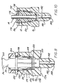
- Fig. 9
- is an exploded, side elevational, longitudinally cross-sectioned view of the female connector and spool after installation of the seal elements in the female connector; and
- Fig. 10
- is a side elevational, longitudinally cross-sectional view of the assembled quick connector of the present invention.
- Referring now to the drawing, and to Fig. 1 in particular, there is depicted the components of a
quick connector 10 including a male connector orspool assembly 12 adapted for connecting a tube orconduit 14, such as a brake line tube, to another component, such as afemale connector 16. - The
female connector 16 may have any applicable exterior configuration depending upon the application. Fig. 1 depicts thefemale connector 16 in the form of ahousing 20 for receiving an in-line brake tube 14. Thehousing 20, as described hereafter and shown in greater detail in Figs. 8-10, has an internal bore or, more preferably, a pair of axially aligned stepped bores which receive at least one seal element, such as an 0-ring 22, atop hat 24, thespool 12, a spring retainer ring orclip 26, and a centeringcollar 28. - The external configuration of the
housing 20 may change relative to the application. For example, in an anti-lock brake system, brake lines may be connected to a housing in the form of a brake manifold or junction having multiple receiving bores therein. Further, the male connector orspool 12 in thehousing 20 is not limited to anti-lock brake systems, but may also be used for any high pressure fluid connection. - According to a unique aspect of the present invention, as shown in Fig. 2, and the assembly sequence of Figs. 3-8, a
stuffer pin 30 is provided for initially mounting the O-ring 22, thetop hat 24 and the retaining 26 within the internal stepped bore of thehousing 20. This enables such components to be premounted within thehousing 20 and protected from damage during shipment from the quick connector manufacturer to the final assembly location. At the assembly location, the spool ormale connector 12 is merely inserted into thehousing 20 in a snap-in connection to complete the fluid connection between thetube 14 and the bore extending through thehousing 20. - As shown in Fig. 2, the
stuffer pin 30 is in the form of a one-piece body, preferably formed of a suitable plastic material. Thestuffer pin 30 includes ashaft 32, astop 34, and ahandle 36. - The
shaft 32 has a tubular elongated shape which may be formed of a single member or, as described in greater detail in U.S. Patent No. 5,472,016, the entire contents of which are incorporated herein by reference, with at least two and preferably four perpendicularly oriented legs, such asopposed legs shaft 32. It will be understood that theshaft 32 may have other shapes, such as a generally solid, cylindrical shape with a smooth outer surface. - The
shaft 32 is integrally joined to thestop 34 at a first end. Asecond end 42 of theshaft 32 extends axially from the first end and thestop 34. - At least one and, preferably, a plurality of
resilient arms 44 are integrally formed on and extend axial outward from thesecond end 42 of theshaft 32. A minimum of two diametricallyopposed arms 44 and, preferably, four equally-circumferentially spacedarms 44 are formed on and extend outward from thesecond end 42 of theshaft 32. Each of thearms 44 is formed with a narrow cross section portion extending from thesecond end 42 so as to be able to resiliently bend or flex inwardly upon mounting of the O-ring 22 andtop hat 24 thereover. - By way of example, each
arm 44 has a generally planar inner side wall which is parallel to the longitudinal axis of theshaft 32. The radially outermost surface of eacharm 44 has a maximum diameterouter edge 46 which is formed on a second side wall of eacharm 44 which is formed of a firstinclined surface 48 extending from thesecond end 42 of theshaft 32 and a second decliningouter edge 50 which extends to theouter surface 50 which extends to the outer end of eacharm 44. - Seal mounting means are formed on the
shaft 32. The seal mounting means comprises anannular recess 52 which extends radially inward between theoutermost edge 46 of eacharm 44 and a radially enlarged central portion of theshaft 32. Therecess 52 cooperates with theouter edge 46 of eacharm 44 to define an area for receiving and maintaining at least one seal element, such as the O-ring 22 and thetop hat 24 in a mounted position on thestuffer pin 30 prior to assembly into thefemale connector 16. - The
stop 34 is the form of a circular disc or flange and has an outer edge with a outer diameter slightly larger than the outer diameter of the enlarged central portion of theshaft 32. Thestop 34 has opposed first andsecond surfaces shaft 32 and thehandle 36, respectively. - A reduced diameter
annular notch 58 is formed on the exterior surface of theshaft 32 between the enlarged central portion of theshaft 32 and thefirst surface 54 of thestop 34. Thenotch 58 forms a retaining ring mounting surface in conjunction with thefirst surface 54 of thestop 34 as described hereafter.
Thehandle 36 extends from thestop 34 generally coaxial with the longitudinal axis of theshaft 32. Thehandle 36 terminates in aflat end portion 60 adjacent to a pair ofopposed notches 62 and facilitates manual insertion and withdrawal of thestuffer pin 30 during assembly of the various components thereon as described hereafter. - Mounting of the 0-
ring 22, thetop hat 24, and the retainingring 26 on thestuffer pin 30 will now be described with reference to Figs. 3-8. - As shown in Figs. 3-6, the initial step is to mount the retaining
ring 26 on thestuffer pin 30. The retainingring 26 may be a generally planar ring having a hollow interior opening or aperture 64. For example, a spiral retaining ring manufactured by Smalley as model no. WHM-62-S02 may be employed. The annular ring portion of the retainingring 26 is split such that two ends are spaced apart to permit radial expansion and contraction of the retainingring 26 as described hereafter. - As shown in Fig. 3, the retaining
ring 26 is inserted into asleeve 66 having an interior through bore 68 extending between afirst end 70 and an opposedsecond end 72. A firstside wall portion 74 of thesleeve 66 tapers from a first smaller diameter at thefirst end 70 to alarger diameter 76 before flaring outward to form askirt 78 of even larger diameter which extends to thesecond end 72. - As shown in Fig. 3, the retaining
ring 26 in its expanded position is inserted into the interior bore 68 insleeve 66 until the retainingring 26 snugly engages the inward tapering surfaces of the firstside wall portion 74 of thesleeve 66 at thefirst diameter 76. - A
pusher 80 is provided for urging the retainingring 26 over thestuffer pin 30 as described hereafter. Thepusher 80 is in the form of a hollow tubular cylindrical member having aninterior bore 82 extending between opposed first and second ends 84 and 86. - The
first end 84 of thepusher 80 is provided with an inner diameter so as to engage the retainingring 26 as thesleeve 66 and thepusher 80 are telescopingly engaged so as to slide the retainingring 26 from the initial mounting position shown in Fig. 3 upward toward thefirst end 70 of thesleeve 66. - Meanwhile, the
stuffer pin 30 is slidably disposed within aretainer collar 90. Theretainer collar 90, formed of a suitable plastic, has a bottle-top configuration formed of aplanar end portion 92 with acentral aperture 94 and a depending annular flange orskirt 96 depending from the outer periphery of theplanar portion 92. Theaperture 94 is sized to slidably receive thehandle 36 of thestuffer pin 30; but is smaller in diameter than the diameter of thestop 34 to prevent the stuffer 30 from sliding through theaperture 94 in theretainer collar 90 past thestop 34. Further, the radially inner end of theskirt 96 has a tapered, depending edge to center theretainer collar 90 on thesleeve 66. - The
retainer collar 90 is in turn supported against ashoulder 98 formed at one end of aholder 100. Theholder 100 has an internal bore 102 projecting from a first end 104 to theshoulder 98. The outer side wall of theholder 100, which is also formed of a suitable plastic material, terminates in an annular radially extending flange which turns into anaxial flange 106 extending generally parallel to theside wall 101. Theshoulder 98 forms a seat for thecollar 90. - As shown in Fig. 4, the
stuffer pin 30 is initially insertedarms 44 first into the hollow end portion of thesleeve 90 with thehandle 36 of thestuffer pin 30 projecting through theaperture 94 in thesleeve 90 into the bore 102 in theholder 100. The joined stufferpin 30,retainer collar 90, andholder 100 as well as thesleeve 66 and thepusher 80 are then urged together to the position shown in Fig. 4 until the end of theretainer collar 90 abuts theend 70 of thesleeve 66. In this position, thefirst end 84 of thepusher 80 engages the retainingring 26 mounted within thesleeve 66. - Further compressive force applied on the
pusher 80 or theholder 100 advances the retainingring 26 along theside wall 74 of thesleeve 66 through the intermediate position shown in Fig. 5 until the retainingring 26 engages thestop 34 on thestuffer pin 30. At the same time, thestop 34 on thestuffer pin 30 engages the inward extending flange on theplanar portion 92 of theretainer collar 90 as shown in Fig. 6. - As the
pusher 80 urges the retainingring 26 along theinner surface 68 of the inward tapering firstside wall portion 74 of thesleeve 66, the spaced ends of the retainingring 26 are compressed or urged together thereby compressing the retainingring 26 into a smallest diameter until the retainingring 26 reaches the smallest diameter shown in Figs. 6 and 7 wherein theretainer ring 26 is positioned within theretainer collar 90. - The
pusher 80, thesleeve 66, and theholder 100 are then disengaged from the retainingcollar 90 and theretainer ring 26 leaving thestuffer pin 30 held within the bore formed within theretainer collar 90 by theaxially extending flange 96 by thecompressed retaining ring 26, as shown in Fig. 7. In this position, thestop 34 on thestuffer pin 30 is sandwiched between the inward tending portion of theplanar end 92 of theretainer collar 90 and thecompressed retaining ring 26. - The
top hat 24, which is formed with anannular ring portion 110 and a pair of axially extendinglegs arms 44 on thestuffer pin 30 by bending theouter edge portion 46 of thearms 44 inward until the inner diameter of the bore through thering portion 110 of thetop hat 24 passes thereover enabling thetop hat 24 to be slid along therecess 52 until an inwardconical seat 116 formed between thering portion 110 and thelegs conical seat 118 formed on thestuffer pin 30 between therecess 52 and the enlarged diameter portion of theshaft 32. Theseal element 22, such as an 0-ring or multi-lip seal is then urged over thearms 44 and seated in therecess 52 between thering portion 110 of thetop hat 24 and the firstinclined surface 48 of eacharm 44 on thestuffer pin 30. Thestuffer pin 30 carrying thetop hat 24 and the 0-ring 22, and the retainingring 26 in theretainer collar 90 is now ready for insertion into thefemale connector 16 as shown in Fig. 8. - As shown in Fig. 8, the
housing 20 of thefemale connector 16 is formed with a first stepped bore 120 of a first diameter. Ashoulder 122 is formed at one end of the first steppedbore 120 and extends radially outward from the inner surface of thefirst bore 120 and merges into a second stepped bore 124 of a second, larger diameter. An outward inclined, generallyconical surface 126 is formed at one end of thesecond bore 124 and extends radially outward to form a third stepped bore 128 of a third diameter. A firstannular groove 130 is formed in the third stepped bore 128 between opposite ends thereof. A secondannular groove 132 is formed in the third stepped bore 128 adjacent oneend 134 of thehousing 20. - An opposed
second end 136 is formed adjacent an enlarged diameter end portion of thehousing 20. Preferably, the enlargeddiameter end portion 138 is formed with a plurality of hex flats. - In an exemplary aspect of the invention, an elongated
tubular shank 140 projects from thesecond end 136 of thehousing 20. Abore 142 extends through theshank 140 to anexterior end 144 of theshank 140. Thebore 142 is disposed in fluid communication with the first stepped bore 120 in thehousing 20. External threads may be formed on theshank 140 for mounting theshank 140 and theentire housing 20 in an external component, not shown. Alternately, theshank 140 may be formed with a smooth exterior surface and provided with an outer diameter for an interference fit in a bore in an external component. Further, theentire housing 20, with or without theshank 140, may be integrally formed as a unitary part of another external component. - With the
stuffer pin 30 assembled as shown in Fig. 7, thestuffer pin 30 is inserted,arms 44 frontmost, into the open end of the third stepped bore 128 in thehousing 20 of the female connector as shown in Fig. 8. The insertion of thestuffer pin 30 continues until the radiallyoutward flange 115 on thetop hat 24 snaps into thefirst groove 130 in thehousing 20. At substantially the same instant, theretainer ring 26 is disposed in line with to thesecond groove 132 in thehousing 20 and expands radially outward into thesecond groove 132 bringing the outer portions of theretainer ring 26 into thesecond groove 132 thereby trapping theretainer ring 26 in thesecond groove 132. This halts further possible insertion of thestuffer pin 30 into thehousing 20. However, as shown in Fig. 6, the expanded O.D. of the retainingring 26 is less than the O.D. of thesecond groove 132, allowing some sideways play or movement of the retainingring 26 within thesecond groove 132. - The
stuffer pin 30 is then removed from thehousing 20 by grasping thehandle 36 and pulling thestuffer pin 30 axially away from theretainer ring 26. The enlargedouter edge 46 on thearms 44 of thestuffer pin 30 engage the O-ring 22 causing thearms 44 to bend radially inward permitting thearms 44 to pass through the narrow diameter bore in the O-ring 22 as well as the bore in thering portion 110 of thetop hat 24. Similarly, thearms 44 bend inward when engaging the inner surfaces of the retainingring 26 until thestuffer pin 30 is free of thehousing 20. It should be noted that the I.D of the retainingring 26, when in the expanding position, is larger than the enlarged portion of theshaft 32 permitting thestuffer pin 30 to pass freely therethrough. - Referring now to Figs. 9 and 10, the insertion of the
spool 12 which carries thetube 14 into thefemale connector 16 will be described. Thespool 12 is in the form of a tube retainer which positively engages a flared end orendform 150 at one end of thetube 14. Thespool 12 is generally in the form of a cylindrical body having a throughbore 152 extending between opposed ends. Thebore 152 has a generally constant diameter cross section which merges at one end with a conical, radially outward extendingseat 154. The conical surface orseat 154 is formed complementary in shape to aconical flange 156 on thetube endform 150 for positively attaching thespool 12 to the conduit ortube 14. By example, oneend 158 of thespool 12 is rolled over the end of theconical flange 156 at one end of thetube 14 to form a tight, metal-to-metal seal between thetube 14 and thespool 12. - Extending from the rolled over
end 158, the body of thespool 12 tapers outwardly to a firstconstant diameter portion 160. Generally intermediate the opposed ends of thespool 12, the body tapers further outwardly at a first angle and then at a shallower angle to form a taperedportion 162 which extends to anend shoulder 164. Asmaller diameter neck 166 projects centrally from theend shoulder 164. Theneck 166 is concentric with thebore 152 and has an outwardly extending,annular flange 168 formed intermediately between the end of theneck 166 and theend shoulder 164. - A centering
collar 170 is mounted on thespool 12 generally in contact with theend shoulder 164 and the outer surface of theneck 166. The centeringcollar 170, which may be formed of a suitable plastic, has a generallyannular end flange 172 and a smallerdiameter center portion 174 projecting therefrom. Abore 176 extends through theend flange 172 and thecenter portion 174 for receiving theneck 166 of thespool 12 and thetube 14 therethrough as shown in Fig. 9. Thecenter portion 174 has a generally circularouter surface 175 of a predetermined diameter. Thecollar 170 can also have an outer surface formed of a plurality of radially extending, equal length arms. - An annular,
inward opening groove 178 is formed in thecenter portion 174 of the centeringcollar 170 for snap connection to theflange 168 on theneck 166 of thespool 12 to mount the centeringcollar 170 on thespool 12. - During assembly, the
spool 12 carrying centeringcollar 170 and thetube 14, as described above, is then inserted into the first, second, and third steppedbores housing 20 of thefemale connector 16 as shown in Fig. 10. Thespool 12 is inserted into the bores in the housing 20 a sufficient distance until the radially outward extendingflange 115 on thetop hat 24 snaps into thefirst groove 130 in third stepped 128 in thehousing 20. This locks thetop hat 24 in position within the stepped bores of thehousing 20 and enables thetop hat 24 to retain the seal or O-ring 22 within the second stepped bore 124 to form a seal between the inner surface of the second stepped bore 124 of thehousing 20 of thefemale connector 16 and the outer surface of theconstant diameter portion 160 of thespool 12. - During the insertion of the
spool 12 into the stepped bores in thehousing 20, the taperedportion 162 of thespool 12 will eventually engage the inner surface of the retainingring 26 which is loosely disposed in thesecond groove 132 in thehousing 20. The outward tapering surface of the taperedportion 162 causes the spaced ends of the retainingring 26 to expand radially outward allowing passage of the large diameter end of the taperedportion 162 past the retainingring 26. At this point, the retainingring 26 snaps under spring force over theend shoulder 162 in thespool 12 into contact with theexterior surface 175 of theend flange 172 on the centeringcollar 170. The diameter of theexterior surface 175 of the centeringcollar 170 is selected such that the retainingcollar 26 remains under spring force and is concentric with the longitudinal axis of thespool 12 and thetube 14. This creates a complete 360° shear surface between the retainingring 26 and thespool 12 to distribute forces on thespool 12 evenly about the circumference of thespool 12 to securely retain thespool 12 in thehousing 20 of thefemale connector 16. - When it is necessary to service the quick connector of the present invention or the components connected to the
tube 14 and/or thefemale connector 16, the centeringcollar 170 is popped out of the end of thehousing 20. With the centeringcollar 170 removed from the end of the bore in thehousing 20, the retainingring 26 can be pulled out of thesecond groove 132 thereby enabling theentire spool 12 to be removed from the stepped bores in thehousing 20. Anew stuffer pin 30, preassembled with the O-ring top hat 24, retainingring 26,retainer collar 90, and centeringcollar 170, and anew spool 12, may be employed to mount theseal elements ring 26 on thehousing 20 of thefemale connector 16 as Well as permitting thespool body 12 and the new centeringcollar 170 to be snap mounted in the stepped bore of thehousing 20 by the retainingring 26 in the same manner as described above. - In summary, there has been disclosed a unique fluid quick connector which has particular advantageous use in high pressure fluid connector applications. By the unique use of a stuffer pin to pre-mount the seal elements and the retainer ring in the housing or body of the female connector, the spool and tube can be shipped from the manufacturer to the final assembly site without a large number of external components mounted thereon. This minimizes potential damage to such components and/or prevents their loss or disengagement from the tube or spool during shipping.
- The quick connector of the present invention also provides a simple push-in, snap connection between the spool and the female connector. This provides an advantageous low insertion force; while still having the requisite high pullout force resistance required for high fluid pressure applications.
- The unique centering collar maintains the retainer ring or clip centered about the end of the spool thereby creating a complete 360° shear surface distributing connection forces equally about the circumference of the spool and the retainer ring.
- Finally, the largest diameter of the tapered portion of the spool body is greater than the nominal inside diameter of the retaining clip in a relaxed position. In this manner, if the spool is not fully inserted into the stepped bore in the housing of the female connector to the seated position wherein the retainer clip snaps behind the end shoulder on the spool body, the expansion forces between the retainer ring and the tapered surface of the spool body will tend to eject the spool body from the bore in the housing to prevent any partial insertion of the spool in the female connector.
Claims (10)
- A quick connector (10) for use with a conduit (14) comprising:a first connector (16) having a bore (120) extending therethrough and a first annular groove (132) opening from the bore and spaced from one end of the first connector;a second connector (12) including a spool having a bore (152) extending therethrough, an end of a conduit mounted in the bore in the spool and establishing a fluid flow path in the second connector;at least one seal element (22, 24) mounted in the bore in the first connector and providing a seal between the bore (120) in the first connector and the spool (12);a retaining ring (26) disposed in the first groove (132) in the first connector, the retaining ring having a through aperture, the retaining ring being radially expandable by insertion of the spool (12) therethrough so as to snap mount the spool in the bore in the first connector upon insertion of the spool to a fully inserted position in the bore in the first connector; and characterized byan annular collar (170) carried by the spool (12) and removably mounted on the spool in a manner to maintain a central axis of the annular collar (170) coaxial with a longitudinal axis of the spool, said collar positioned between the spool (12) and the retaining ring (26) for centering the retaining ring with respect to said longitudinal spool axis.
- The quick connector (10) of claim 1 further comprising:means (168), carried on the collar and the spool for mounting the collar on the spool.
- The quick connector (10) of claim 1 wherein
the collar (170) has a circular outer surface (175) engagable with the retaining ring to center the retaining ring with respect to the longitudinal axis through the spool. - The quick connector (10) of claim 1 further comprising:a second groove (130) formed in the first connector (16) and opening to the bore (120) in the first connector;the seal element including a first seal (24) having a radially outward extending flange (115), the radially outward extending flange engagable with the second groove to mount the first seal in a fixed position within the bore in the first connector.
- The quick connector (10) of claim 4 wherein the seal element further comprises:a resilient second seal (22) interposed between the first seal (24) and one end of the bore (122) in the first connector.
- A method of assembling a quick connector (10) formed of a housing (20) having a through bore (120), a spool (12) carrying a tube (14) having a through bore, at least one seal element (22, 24) and a retaining ring (26), the method comprising the steps of:pre-mounting the seal element (22, 24) in the bore and the retainer ring (26) in a first annular groove opening from the bore (120) in the housing; andthen snap mounting the spool (12) in the bore in the housing;centering the retaining ring (26) with respect to a longitudinal axis extending through the spool when the spool is fully inserted into the bore in the housing; characterized byproviding a collar (170) having a circular outer surface (175);removably mounting the collar (170) over the spool (12) such that the outer surface of the collar engages the retaining ring to concentrically center the retaining ring with respect to a longitudinal axis through the bore in the spool.
- The method of claim 6 wherein the snap-mounting steps comprises:providing the spool (12) with an outwardly tapered surface (162) for expanding the retaining ring (26) from a nominal diameter to an expanded diameter during insertion of the spool through the retaining ring to permit the retaining ring to snap behind an end of the spool (12) upon full insertion of the spool.
- The method of claim 6 wherein the step of pre-mounting the seal (22, 24) and retainer ring (26) in the bore in the housing comprises the steps of:mounting the retaining ring (26) in a conical sleeve having inward tapered side walls converging from a first end in which the retaining ring is initially mounted to an opposed second end;providing an elongated stuffer pin (30);mounting a retainer collar over one end of the stuffer pin, the retainer collar having an annular flange with an inner diameter equal to a diameter of the second end of the sleeve;urging the retaining ring from the first to the second ends of the sleeve to compress the retaining ring while the sliding the retaining ring and the stuffer pin relative to each other to compressively mount the retainer ring about the stuffer pin;mounting the one seal element on the stuffer pin spaced from the retaining ring;sliding the stuffer pin (30) into the bore in the housing;fixing the one seal element (22) in a predetermined position within the bore in the housing;engaging the retainer ring in an annular groove opening to the bore in the housing wherein the retaining ring expands radially outward from a compressed state; anddisengaging the stuffer pin from the seal element and the retainer ring mounted in the bore in the housing.
- The method of claim 6 further comprising the step of:mounting another seal element (24) about the stuffer pin in proximity with the one seal element (22).
- The method of claim 6 wherein the step of fixing the one seal element further comprises the steps of:providing another annular groove in the bore in the housing opening to the bore in the housing;providing the one seal element with a radially outward flange snap engagable with the another groove to fix the one seal element in a predetermined position within the bore in the housing.
Applications Claiming Priority (2)
| Application Number | Priority Date | Filing Date | Title |
|---|---|---|---|
| US457210 | 1999-12-08 | ||
| US09/457,210 US6378908B1 (en) | 1999-12-08 | 1999-12-08 | High pressure quick connector |
Publications (2)
| Publication Number | Publication Date |
|---|---|
| EP1106897A1 EP1106897A1 (en) | 2001-06-13 |
| EP1106897B1 true EP1106897B1 (en) | 2005-09-21 |
Family
ID=23815849
Family Applications (1)
| Application Number | Title | Priority Date | Filing Date |
|---|---|---|---|
| EP00126645A Expired - Lifetime EP1106897B1 (en) | 1999-12-08 | 2000-12-04 | High pressure quick connector and method of assembly |
Country Status (4)
| Country | Link |
|---|---|
| US (1) | US6378908B1 (en) |
| EP (1) | EP1106897B1 (en) |
| JP (1) | JP3842547B2 (en) |
| DE (1) | DE60022725T2 (en) |
Families Citing this family (13)
| Publication number | Priority date | Publication date | Assignee | Title |
|---|---|---|---|---|
| TW200602577A (en) * | 2004-04-22 | 2006-01-16 | Swagelok Co | Fitting for tube and pipe |
| JP5277475B2 (en) * | 2006-05-01 | 2013-08-28 | シェフラー テクノロジーズ アクチエンゲゼルシャフト ウント コンパニー コマンディートゲゼルシャフト | One-way clutch with damping function |
| US7581760B2 (en) * | 2006-05-31 | 2009-09-01 | Yh America, Inc. | Hose coupling endform for fluid transfer assemblies |
| US7581761B2 (en) * | 2006-06-01 | 2009-09-01 | Yh America, Inc. | Asymmetric hose coupling endform for fluid transfer assemblies |
| WO2008057983A1 (en) | 2006-11-02 | 2008-05-15 | Swagelok Company | Pull-up by torque fitting |
| US7819436B2 (en) * | 2007-06-27 | 2010-10-26 | Yh America, Inc. | Endformed tubular assembly |
| US7837041B2 (en) * | 2007-06-27 | 2010-11-23 | Yh America, Inc. | Method of determining the robustness of endformed tubular assembly and predicting the performance of such assembly in high pressure applications |
| US7870655B2 (en) * | 2007-06-27 | 2011-01-18 | Yh America, Inc. | Process of endforming a tubular assembly |
| WO2009020900A2 (en) | 2007-08-03 | 2009-02-12 | Swagelok Company | Pull-up by torque ferrule fitting |
| DE102012102256A1 (en) | 2012-03-16 | 2013-09-19 | Endress + Hauser Conducta Gesellschaft für Mess- und Regeltechnik mbH + Co. KG | Analyzer with base module and exchangeable cassette |
| US10781958B2 (en) * | 2017-10-31 | 2020-09-22 | Oetiker Ny, Inc. | Low peak insertion tube end form |
| EP3736481B1 (en) * | 2019-05-07 | 2022-01-19 | A. Raymond et Cie | Quick connector assembly with verification tab |
| EP4279347A1 (en) * | 2022-05-17 | 2023-11-22 | Arfesan Arkan Fren Elemanlari Sanayi Ve Ticaret A.S. | An air connection apparatus |
Family Cites Families (20)
| Publication number | Priority date | Publication date | Assignee | Title |
|---|---|---|---|---|
| US2521127A (en) * | 1948-05-08 | 1950-09-05 | Wright Aeronautical Corp | Fluid tight joint |
| US3404904A (en) * | 1966-01-17 | 1968-10-08 | Holmberg Inc | Pipe couplings |
| FR2283381A1 (en) * | 1974-03-15 | 1976-03-26 | Sogemo Automatisation | IMPROVEMENTS IN CONNECTION SYSTEMS FOR DUCTS, ESPECIALLY FOR SEMI-RIGID PLASTIC TUBES |
| US3944263A (en) * | 1975-03-14 | 1976-03-16 | Hydrotech International, Inc. | Dynamic pipe coupling |
| DE2824943C2 (en) | 1978-06-07 | 1986-07-31 | Armaturenfabrik Hermann Voss GmbH + Co, 5272 Wipperfürth | Connection device for brake lines |
| US4915136A (en) | 1980-10-29 | 1990-04-10 | Proprietary Technology, Inc. | Stuffer plug quick connector assembly |
| JPS59150087U (en) * | 1983-03-26 | 1984-10-06 | 千代田通商株式会社 | hose fitting |
| US4884829A (en) | 1986-09-16 | 1989-12-05 | Johannes Schaefer Vorm. Stettiner Schraubenwerke Gmbh & Co. Kg | Plug-in connection for connecting tube and host lines in particular for use in tube-line systems of motor vehicles |
| DE3806404C2 (en) * | 1988-02-29 | 1994-06-09 | Raymond A Gmbh & Co Kg | Detachable connector for semi-rigid pipes |
| IT1216491B (en) * | 1988-03-22 | 1990-03-08 | Finimpresa Spa | QUICK CONNECTION FITTING FOR FLEXIBLE HOSES WITH CONICAL RETAINING RING. |
| US5538297A (en) | 1991-09-10 | 1996-07-23 | Bundy Corporation | Quick connect tubing connector |
| US5297818A (en) | 1991-12-18 | 1994-03-29 | Itt Corporation | Retainer for pop-top indicator |
| US5374089A (en) | 1992-09-29 | 1994-12-20 | Itt Industries Inc. | High pressure quick connector |
| US5472016A (en) | 1993-10-04 | 1995-12-05 | Itt Corporation | Quick connector stuffer pin |
| US5486025A (en) | 1994-09-29 | 1996-01-23 | Bundy Corporation | Stuffer pin assembly for quick connector |
| US5711549A (en) | 1995-06-07 | 1998-01-27 | Itt Automotive, Inc. | High pressure quick connect for use in automotive brake system application |
| GB9615394D0 (en) | 1996-07-23 | 1996-09-04 | Rolls Royce Plc | Gas turbine engine rotor disc with cooling fluid passage |
| US6073973A (en) * | 1996-10-31 | 2000-06-13 | Stanley Aviation Corporation | Lightweight positive lock coupling |
| US5882049A (en) * | 1996-12-18 | 1999-03-16 | Itt Automotive, Inc. | High pressure quick connect with reduced volumetric displacement and piloted snap ring |
| EP0905431A3 (en) * | 1997-09-30 | 1999-09-15 | Aeroquip-Vickers International GmbH | Coupling device |
-
1999
- 1999-12-08 US US09/457,210 patent/US6378908B1/en not_active Expired - Fee Related
-
2000
- 2000-12-04 EP EP00126645A patent/EP1106897B1/en not_active Expired - Lifetime
- 2000-12-04 DE DE60022725T patent/DE60022725T2/en not_active Expired - Lifetime
- 2000-12-08 JP JP2000374421A patent/JP3842547B2/en not_active Expired - Lifetime
Also Published As
| Publication number | Publication date |
|---|---|
| EP1106897A1 (en) | 2001-06-13 |
| DE60022725D1 (en) | 2005-10-27 |
| DE60022725T2 (en) | 2006-06-22 |
| US6378908B1 (en) | 2002-04-30 |
| JP2001200973A (en) | 2001-07-27 |
| JP3842547B2 (en) | 2006-11-08 |
Similar Documents
| Publication | Publication Date | Title |
|---|---|---|
| US7467813B2 (en) | Quick connector | |
| US5897142A (en) | Push-to-release quick connector | |
| US5511830A (en) | Quick connect tube couplings | |
| US7891380B2 (en) | Protective cap for quick connector | |
| US4948175A (en) | Swivelable quick connector assembly | |
| EP0659126B1 (en) | Sliding collar quick connect | |
| US4601497A (en) | Swivelable quick connector assembly | |
| EP1106897B1 (en) | High pressure quick connector and method of assembly | |
| US5711549A (en) | High pressure quick connect for use in automotive brake system application | |
| JPH09506152A (en) | Quick connector housing with long thin barb design | |
| EP0796405A1 (en) | Squeeze-to-release quick connector with snap-in retainer | |
| JPH09503574A (en) | Quick connector with integral release member | |
| US6234544B1 (en) | Quick connector with confirmation feature | |
| US7891710B2 (en) | Connector with release mechanism, and method for forming a releasable fluid connection | |
| US5775738A (en) | Means of coupling of non-threaded connections | |
| US5927761A (en) | Means of coupling of non-threaded connections | |
| US7857360B2 (en) | Snap-in-place valved coupler | |
| EP0660907B1 (en) | Tubular assembly and method of making same | |
| US6412826B1 (en) | High pressure quick connector | |
| US20030001384A1 (en) | Seal cap and connector assembly | |
| US6086113A (en) | Means of coupling of non-threaded connections | |
| EP0852682A1 (en) | Quick connector with confirmation feature | |
| WO2023101701A1 (en) | Fluid connection assembly with a retainer holder | |
| MXPA98002365A (en) | Fast connector with confirmac features | |
| CA2232856A1 (en) | Quick connector with confirmation feature |
Legal Events
| Date | Code | Title | Description |
|---|---|---|---|
| PUAI | Public reference made under article 153(3) epc to a published international application that has entered the european phase |
Free format text: ORIGINAL CODE: 0009012 |
|
| AK | Designated contracting states |
Kind code of ref document: A1 Designated state(s): DE FR GB |
|
| AX | Request for extension of the european patent |
Free format text: AL;LT;LV;MK;RO;SI |
|
| 17P | Request for examination filed |
Effective date: 20011213 |
|
| AKX | Designation fees paid |
Free format text: DE FR GB |
|
| 17Q | First examination report despatched |
Effective date: 20040512 |
|
| GRAP | Despatch of communication of intention to grant a patent |
Free format text: ORIGINAL CODE: EPIDOSNIGR1 |
|
| GRAS | Grant fee paid |
Free format text: ORIGINAL CODE: EPIDOSNIGR3 |
|
| GRAA | (expected) grant |
Free format text: ORIGINAL CODE: 0009210 |
|
| AK | Designated contracting states |
Kind code of ref document: B1 Designated state(s): DE FR GB |
|
| REG | Reference to a national code |
Ref country code: GB Ref legal event code: FG4D |
|
| REF | Corresponds to: |
Ref document number: 60022725 Country of ref document: DE Date of ref document: 20051027 Kind code of ref document: P |
|
| ET | Fr: translation filed | ||
| PLBE | No opposition filed within time limit |
Free format text: ORIGINAL CODE: 0009261 |
|
| STAA | Information on the status of an ep patent application or granted ep patent |
Free format text: STATUS: NO OPPOSITION FILED WITHIN TIME LIMIT |
|
| 26N | No opposition filed |
Effective date: 20060622 |
|
| REG | Reference to a national code |
Ref country code: FR Ref legal event code: PLFP Year of fee payment: 16 |
|
| REG | Reference to a national code |
Ref country code: FR Ref legal event code: PLFP Year of fee payment: 17 |
|
| REG | Reference to a national code |
Ref country code: FR Ref legal event code: PLFP Year of fee payment: 18 |
|
| PGFP | Annual fee paid to national office [announced via postgrant information from national office to epo] |
Ref country code: FR Payment date: 20191226 Year of fee payment: 20 |
|
| PGFP | Annual fee paid to national office [announced via postgrant information from national office to epo] |
Ref country code: DE Payment date: 20191231 Year of fee payment: 20 Ref country code: GB Payment date: 20200102 Year of fee payment: 20 |
|
| REG | Reference to a national code |
Ref country code: DE Ref legal event code: R071 Ref document number: 60022725 Country of ref document: DE |
|
| REG | Reference to a national code |
Ref country code: GB Ref legal event code: PE20 Expiry date: 20201203 |
|
| PG25 | Lapsed in a contracting state [announced via postgrant information from national office to epo] |
Ref country code: GB Free format text: LAPSE BECAUSE OF EXPIRATION OF PROTECTION Effective date: 20201203 |