EP1106140B2 - Blutentnahmegerät - Google Patents
Blutentnahmegerät Download PDFInfo
- Publication number
- EP1106140B2 EP1106140B2 EP00310829A EP00310829A EP1106140B2 EP 1106140 B2 EP1106140 B2 EP 1106140B2 EP 00310829 A EP00310829 A EP 00310829A EP 00310829 A EP00310829 A EP 00310829A EP 1106140 B2 EP1106140 B2 EP 1106140B2
- Authority
- EP
- European Patent Office
- Prior art keywords
- blood
- collecting device
- coagulation agent
- outer cylinder
- supply piece
- Prior art date
- Legal status (The legal status is an assumption and is not a legal conclusion. Google has not performed a legal analysis and makes no representation as to the accuracy of the status listed.)
- Expired - Lifetime
Links
- 239000003146 anticoagulant agent Substances 0.000 claims abstract description 124
- 239000008280 blood Substances 0.000 claims abstract description 111
- 210000004369 blood Anatomy 0.000 claims abstract description 111
- 239000000463 material Substances 0.000 claims description 44
- 238000001035 drying Methods 0.000 claims description 10
- 239000007788 liquid Substances 0.000 claims description 9
- 238000009423 ventilation Methods 0.000 claims description 4
- 239000002985 plastic film Substances 0.000 claims description 2
- 229940127090 anticoagulant agent Drugs 0.000 claims 2
- 229920006255 plastic film Polymers 0.000 claims 1
- 229920000669 heparin Polymers 0.000 abstract description 59
- HTTJABKRGRZYRN-UHFFFAOYSA-N Heparin Chemical compound OC1C(NC(=O)C)C(O)OC(COS(O)(=O)=O)C1OC1C(OS(O)(=O)=O)C(O)C(OC2C(C(OS(O)(=O)=O)C(OC3C(C(O)C(O)C(O3)C(O)=O)OS(O)(=O)=O)C(CO)O2)NS(O)(=O)=O)C(C(O)=O)O1 HTTJABKRGRZYRN-UHFFFAOYSA-N 0.000 abstract description 57
- 229960002897 heparin Drugs 0.000 abstract description 57
- 230000000052 comparative effect Effects 0.000 description 32
- 238000000034 method Methods 0.000 description 20
- 238000004108 freeze drying Methods 0.000 description 13
- -1 polyethylene Polymers 0.000 description 13
- 239000004698 Polyethylene Substances 0.000 description 12
- 230000023555 blood coagulation Effects 0.000 description 12
- 229920000139 polyethylene terephthalate Polymers 0.000 description 11
- 239000005020 polyethylene terephthalate Substances 0.000 description 11
- 239000011148 porous material Substances 0.000 description 10
- KRKNYBCHXYNGOX-UHFFFAOYSA-N citric acid Chemical compound OC(=O)CC(O)(C(O)=O)CC(O)=O KRKNYBCHXYNGOX-UHFFFAOYSA-N 0.000 description 9
- 230000000694 effects Effects 0.000 description 9
- 230000004888 barrier function Effects 0.000 description 8
- 238000010521 absorption reaction Methods 0.000 description 7
- 238000004519 manufacturing process Methods 0.000 description 7
- 238000002156 mixing Methods 0.000 description 7
- 230000010100 anticoagulation Effects 0.000 description 6
- 239000007864 aqueous solution Substances 0.000 description 6
- 238000002474 experimental method Methods 0.000 description 6
- 239000000203 mixture Substances 0.000 description 6
- 239000004743 Polypropylene Substances 0.000 description 5
- 238000005259 measurement Methods 0.000 description 5
- 229920001155 polypropylene Polymers 0.000 description 5
- 210000001367 artery Anatomy 0.000 description 4
- 239000007789 gas Substances 0.000 description 4
- 229920000728 polyester Polymers 0.000 description 4
- 229920000573 polyethylene Polymers 0.000 description 4
- 239000011347 resin Substances 0.000 description 4
- 229920005989 resin Polymers 0.000 description 4
- 238000002791 soaking Methods 0.000 description 4
- WQZGKKKJIJFFOK-GASJEMHNSA-N Glucose Chemical compound OC[C@H]1OC(O)[C@H](O)[C@@H](O)[C@@H]1O WQZGKKKJIJFFOK-GASJEMHNSA-N 0.000 description 3
- XAGFODPZIPBFFR-UHFFFAOYSA-N aluminium Chemical compound [Al] XAGFODPZIPBFFR-UHFFFAOYSA-N 0.000 description 3
- 229910052782 aluminium Inorganic materials 0.000 description 3
- QVGXLLKOCUKJST-UHFFFAOYSA-N atomic oxygen Chemical compound [O] QVGXLLKOCUKJST-UHFFFAOYSA-N 0.000 description 3
- 230000036772 blood pressure Effects 0.000 description 3
- 230000007850 degeneration Effects 0.000 description 3
- 238000004090 dissolution Methods 0.000 description 3
- 239000001301 oxygen Substances 0.000 description 3
- 229910052760 oxygen Inorganic materials 0.000 description 3
- 229920002647 polyamide Polymers 0.000 description 3
- 229920000036 polyvinylpyrrolidone Polymers 0.000 description 3
- 239000001267 polyvinylpyrrolidone Substances 0.000 description 3
- 235000013855 polyvinylpyrrolidone Nutrition 0.000 description 3
- 239000001509 sodium citrate Substances 0.000 description 3
- NLJMYIDDQXHKNR-UHFFFAOYSA-K sodium citrate Chemical compound O.O.[Na+].[Na+].[Na+].[O-]C(=O)CC(O)(CC([O-])=O)C([O-])=O NLJMYIDDQXHKNR-UHFFFAOYSA-K 0.000 description 3
- 239000000243 solution Substances 0.000 description 3
- 229920000178 Acrylic resin Polymers 0.000 description 2
- 239000004925 Acrylic resin Substances 0.000 description 2
- 239000004677 Nylon Substances 0.000 description 2
- 239000004952 Polyamide Substances 0.000 description 2
- 239000004793 Polystyrene Substances 0.000 description 2
- FAPWRFPIFSIZLT-UHFFFAOYSA-M Sodium chloride Chemical compound [Na+].[Cl-] FAPWRFPIFSIZLT-UHFFFAOYSA-M 0.000 description 2
- PPBRXRYQALVLMV-UHFFFAOYSA-N Styrene Chemical compound C=CC1=CC=CC=C1 PPBRXRYQALVLMV-UHFFFAOYSA-N 0.000 description 2
- 230000017531 blood circulation Effects 0.000 description 2
- 239000003795 chemical substances by application Substances 0.000 description 2
- 229920001577 copolymer Polymers 0.000 description 2
- 238000010586 diagram Methods 0.000 description 2
- 238000007599 discharging Methods 0.000 description 2
- 239000013013 elastic material Substances 0.000 description 2
- 238000011156 evaluation Methods 0.000 description 2
- 239000004745 nonwoven fabric Substances 0.000 description 2
- 229920001778 nylon Polymers 0.000 description 2
- 230000002093 peripheral effect Effects 0.000 description 2
- 239000002504 physiological saline solution Substances 0.000 description 2
- 229920000642 polymer Polymers 0.000 description 2
- 229920000306 polymethylpentene Polymers 0.000 description 2
- 229920002223 polystyrene Polymers 0.000 description 2
- 229920000915 polyvinyl chloride Polymers 0.000 description 2
- 239000004800 polyvinyl chloride Substances 0.000 description 2
- 230000002265 prevention Effects 0.000 description 2
- 239000000047 product Substances 0.000 description 2
- 238000003908 quality control method Methods 0.000 description 2
- 230000000452 restraining effect Effects 0.000 description 2
- 229920002379 silicone rubber Polymers 0.000 description 2
- 239000004945 silicone rubber Substances 0.000 description 2
- 230000001954 sterilising effect Effects 0.000 description 2
- 238000004659 sterilization and disinfection Methods 0.000 description 2
- RYFMWSXOAZQYPI-UHFFFAOYSA-K trisodium phosphate Chemical compound [Na+].[Na+].[Na+].[O-]P([O-])([O-])=O RYFMWSXOAZQYPI-UHFFFAOYSA-K 0.000 description 2
- RZSIBGYUCGYDKG-VIFPVBQESA-N (3s)-3-methyl-1-[4-(trifluoromethyl)-1-benzofuran-7-yl]piperazine Chemical compound C1CN[C@@H](C)CN1C1=CC=C(C(F)(F)F)C2=C1OC=C2 RZSIBGYUCGYDKG-VIFPVBQESA-N 0.000 description 1
- GFFGJBXGBJISGV-UHFFFAOYSA-N Adenine Chemical compound NC1=NC=NC2=C1N=CN2 GFFGJBXGBJISGV-UHFFFAOYSA-N 0.000 description 1
- 229930024421 Adenine Natural products 0.000 description 1
- 229920002799 BoPET Polymers 0.000 description 1
- 240000001980 Cucurbita pepo Species 0.000 description 1
- 235000009852 Cucurbita pepo Nutrition 0.000 description 1
- KCXVZYZYPLLWCC-UHFFFAOYSA-N EDTA Chemical compound OC(=O)CN(CC(O)=O)CCN(CC(O)=O)CC(O)=O KCXVZYZYPLLWCC-UHFFFAOYSA-N 0.000 description 1
- 244000043261 Hevea brasiliensis Species 0.000 description 1
- JHWNWJKBPDFINM-UHFFFAOYSA-N Laurolactam Chemical compound O=C1CCCCCCCCCCCN1 JHWNWJKBPDFINM-UHFFFAOYSA-N 0.000 description 1
- 229920000299 Nylon 12 Polymers 0.000 description 1
- 229920002292 Nylon 6 Polymers 0.000 description 1
- 239000005062 Polybutadiene Substances 0.000 description 1
- VYPSYNLAJGMNEJ-UHFFFAOYSA-N Silicium dioxide Chemical compound O=[Si]=O VYPSYNLAJGMNEJ-UHFFFAOYSA-N 0.000 description 1
- 229920002472 Starch Polymers 0.000 description 1
- 102000003990 Urokinase-type plasminogen activator Human genes 0.000 description 1
- 108090000435 Urokinase-type plasminogen activator Proteins 0.000 description 1
- 230000002745 absorbent Effects 0.000 description 1
- 239000002250 absorbent Substances 0.000 description 1
- NIXOWILDQLNWCW-UHFFFAOYSA-N acrylic acid group Chemical group C(C=C)(=O)O NIXOWILDQLNWCW-UHFFFAOYSA-N 0.000 description 1
- 229960000643 adenine Drugs 0.000 description 1
- 230000002411 adverse Effects 0.000 description 1
- 238000007605 air drying Methods 0.000 description 1
- 150000001336 alkenes Chemical class 0.000 description 1
- 230000000903 blocking effect Effects 0.000 description 1
- 229920005549 butyl rubber Polymers 0.000 description 1
- 238000010981 drying operation Methods 0.000 description 1
- 229920001971 elastomer Polymers 0.000 description 1
- 238000010894 electron beam technology Methods 0.000 description 1
- 238000010828 elution Methods 0.000 description 1
- 238000004388 gamma ray sterilization Methods 0.000 description 1
- ZFGMDIBRIDKWMY-PASTXAENSA-N heparin Chemical compound CC(O)=N[C@@H]1[C@@H](O)[C@H](O)[C@@H](COS(O)(=O)=O)O[C@@H]1O[C@@H]1[C@@H](C(O)=O)O[C@@H](O[C@H]2[C@@H]([C@@H](OS(O)(=O)=O)[C@@H](O[C@@H]3[C@@H](OC(O)[C@H](OS(O)(=O)=O)[C@H]3O)C(O)=O)O[C@@H]2O)CS(O)(=O)=O)[C@H](O)[C@H]1O ZFGMDIBRIDKWMY-PASTXAENSA-N 0.000 description 1
- 230000002209 hydrophobic effect Effects 0.000 description 1
- 230000004941 influx Effects 0.000 description 1
- 229920000554 ionomer Polymers 0.000 description 1
- 229920003049 isoprene rubber Polymers 0.000 description 1
- 239000012528 membrane Substances 0.000 description 1
- 229920003052 natural elastomer Polymers 0.000 description 1
- 229920001194 natural rubber Polymers 0.000 description 1
- JRZJOMJEPLMPRA-UHFFFAOYSA-N olefin Natural products CCCCCCCC=C JRZJOMJEPLMPRA-UHFFFAOYSA-N 0.000 description 1
- 239000012466 permeate Substances 0.000 description 1
- 229920003023 plastic Polymers 0.000 description 1
- 229920002857 polybutadiene Polymers 0.000 description 1
- 239000004417 polycarbonate Substances 0.000 description 1
- 229920000515 polycarbonate Polymers 0.000 description 1
- 239000002861 polymer material Substances 0.000 description 1
- 229920002635 polyurethane Polymers 0.000 description 1
- 239000004814 polyurethane Substances 0.000 description 1
- 239000005060 rubber Substances 0.000 description 1
- 238000007493 shaping process Methods 0.000 description 1
- 238000005245 sintering Methods 0.000 description 1
- 239000011780 sodium chloride Substances 0.000 description 1
- 239000007921 spray Substances 0.000 description 1
- 235000019698 starch Nutrition 0.000 description 1
- 239000008107 starch Substances 0.000 description 1
- 229920003048 styrene butadiene rubber Polymers 0.000 description 1
- JZBRFIUYUGTUGG-UHFFFAOYSA-J tetrapotassium;2-[2-[bis(carboxylatomethyl)amino]ethyl-(carboxylatomethyl)amino]acetate Chemical compound [K+].[K+].[K+].[K+].[O-]C(=O)CN(CC([O-])=O)CCN(CC([O-])=O)CC([O-])=O JZBRFIUYUGTUGG-UHFFFAOYSA-J 0.000 description 1
- 229920002725 thermoplastic elastomer Polymers 0.000 description 1
- 229960005356 urokinase Drugs 0.000 description 1
- 239000002759 woven fabric Substances 0.000 description 1
Images


Classifications
-
- A—HUMAN NECESSITIES
- A61—MEDICAL OR VETERINARY SCIENCE; HYGIENE
- A61B—DIAGNOSIS; SURGERY; IDENTIFICATION
- A61B5/00—Measuring for diagnostic purposes; Identification of persons
- A61B5/15—Devices for taking samples of blood
- A61B5/153—Devices specially adapted for taking samples of venous or arterial blood, e.g. with syringes
-
- A—HUMAN NECESSITIES
- A61—MEDICAL OR VETERINARY SCIENCE; HYGIENE
- A61B—DIAGNOSIS; SURGERY; IDENTIFICATION
- A61B5/00—Measuring for diagnostic purposes; Identification of persons
- A61B5/15—Devices for taking samples of blood
- A61B5/150007—Details
- A61B5/150015—Source of blood
- A61B5/15003—Source of blood for venous or arterial blood
-
- A—HUMAN NECESSITIES
- A61—MEDICAL OR VETERINARY SCIENCE; HYGIENE
- A61B—DIAGNOSIS; SURGERY; IDENTIFICATION
- A61B5/00—Measuring for diagnostic purposes; Identification of persons
- A61B5/15—Devices for taking samples of blood
- A61B5/150007—Details
- A61B5/150206—Construction or design features not otherwise provided for; manufacturing or production; packages; sterilisation of piercing element, piercing device or sampling device
- A61B5/150213—Venting means
-
- A—HUMAN NECESSITIES
- A61—MEDICAL OR VETERINARY SCIENCE; HYGIENE
- A61B—DIAGNOSIS; SURGERY; IDENTIFICATION
- A61B5/00—Measuring for diagnostic purposes; Identification of persons
- A61B5/15—Devices for taking samples of blood
- A61B5/150007—Details
- A61B5/150206—Construction or design features not otherwise provided for; manufacturing or production; packages; sterilisation of piercing element, piercing device or sampling device
- A61B5/150236—Pistons, i.e. cylindrical bodies that sit inside the syringe barrel, typically with an air tight seal, and slide in the barrel to create a vacuum or to expel blood
-
- A—HUMAN NECESSITIES
- A61—MEDICAL OR VETERINARY SCIENCE; HYGIENE
- A61B—DIAGNOSIS; SURGERY; IDENTIFICATION
- A61B5/00—Measuring for diagnostic purposes; Identification of persons
- A61B5/15—Devices for taking samples of blood
- A61B5/150007—Details
- A61B5/150206—Construction or design features not otherwise provided for; manufacturing or production; packages; sterilisation of piercing element, piercing device or sampling device
- A61B5/150244—Rods for actuating or driving the piston, i.e. the cylindrical body that sits inside the syringe barrel, typically with an air tight seal, and slides in the barrel to create a vacuum or to expel blood
-
- A—HUMAN NECESSITIES
- A61—MEDICAL OR VETERINARY SCIENCE; HYGIENE
- A61B—DIAGNOSIS; SURGERY; IDENTIFICATION
- A61B5/00—Measuring for diagnostic purposes; Identification of persons
- A61B5/15—Devices for taking samples of blood
- A61B5/150007—Details
- A61B5/150755—Blood sample preparation for further analysis, e.g. by separating blood components or by mixing
Definitions
- the present invention relates to a blood-collecting device to be used for collecting the blood, in particular, it relates to an arterial blood-collecting device for collecting the arterial blood.
- an arterial blood-collecting device used therefor has a configuration wherein the blood is introduced into the blood-collecting device according to the blood pressure in the artery.
- the air in the syringe should be discharged to the outside as the blood is introduced into the syringe of the blood-collecting device by the blood pressure, the inside and the outside of the syringe can be ventilated via a filter member.
- an anti-coagulation agent such as heparin is provided in the syringe of the arterial blood-collecting device.
- freeze-dried heparin can easily absorbs moisture so as to be liquidized due to the generated deliquescence phenomenon. Therefore, problems arise in that:
- the entirety of the arterial blood-collecting device should be wrapped in a special wrapping material having the excellent vapor barrier property, such as a wrapping material comprising a laminated film having an aluminum thin layer.
- An object of the invention is to provide a bleod-collecting device with the excellent solubility and mixing property of an anti-coagulation agent with respect to the blood, without the need of a freeze-drying process of an anti-coagulation agent, capable of eliminating or reducing (alleviating) a moisture prevention measure and restraining mixture of bubbles into the collected blood, and further, with a good production efficiency.
- the object can be achieved by the below-mentioned blood-collecting devices according to the invention.
- the object of the invention can be achieved by a blood-collecting device comprising an outer cylinder having a blood inlet opening, a gasket slidable in the outer cylinder, a plunger for the moving operation of the gasket, and an anti-coagulation agent supply piece with an anti-coagulation agent supported on at least one side of a plate-like supporting member, provided in a space surrounded by the outer cylinder and the gasket.
- the anti-coagulation agent supply piece has a shape tapered toward the blood inlet opening.
- the tip end of the tapered shape is pointed.
- the tip end of the tapered shape is disposed in the blood inlet opening.
- the anti-coagulation agent supply piece maintains its posture by linear contact of the rim part with the inner surface of the outer cylinder.
- the object of the invention can be achieved by a blood-collecting device comprising an outer cylinder having a blood inlet opening, a gasket slidable in the outer cylinder, a plunger for the moving operation of the gasket, and an anti-coagulation agent supply piece with an anti-coagulation agent supported on at least one side of a plate-like supporting member, provided in a space surrounded by the outer cylinder and the gasket, wherein the anti-coagulation agent supply piece maintains its posture by linear contact of the rim part with the inner surface of the outer cylinder,.
- the object of the invention can be achieved by a blood-collecting device comprising an outer cylinder having a blood inlet opening, a gasket slidable in the outer cylinder, a plunger for the moving operation of the gasket, and an anti-coagulation agent supply piece with an anti-coagulation agent supported on at least one side of a plate-like supporting member, provided in a space surrounded by the outer cylinder and the gasket, wherein the anti-coagulation agent supply piece maintains its posture by linear contact of a pair of rim parts facing with each other with the inner surface of the outer cylinder.
- a seventh aspect of the invention comprising the blood-collecting device of the sixth aspect, it is preferable that the lengths of the pair of the rim parts are substantially equal.
- the anti-coagulation agent supply piece has a polygonal shape.
- the plate-like supporting member is made of a material insoluble with respect to the blood.
- the plate-like supporting member is made of a non-porous material.
- an eleventh aspect of the invention comprising the blood-collecting device of the first or tenth aspect, it is preferable that minute ruggedness is formed on the surface of the plate-like supporting member in contact with the anti-coagulation agent.
- the anti-coagulation agent is supported by applying a solution of the anti-coagulation agent on the surface of the plate-like supporting member, and drying at an ordinary temperature or higher.
- the anti-coagulation agent supply piece is disposed in a direction substantially parallel with the longitudinal direction of the outer cylinder
- a ventilation part is formed in the gasket and the plunger.
- a gas permeable filter member not allowing permeation of a liquid is provided in the gasket.
- the anti-coagulation agent is a heparin.
- the blood-collecting device according to the first or sixteenth aspect is suitable for collecting the arterial blood.
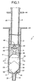
- FIG. 1 is a vertical cross-sectional view showing an embodiment of a blood-collecting device of the invention.
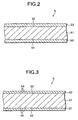
- FIGS. 2 and 3 are cross-sectional views each showing a configuration example of an anti-coagulation agent supply piece.
- FIG. 4 is a cross-sectional view taken on the line A-A of FIG. 1.
- the upper side in FIG. 1 is referred to as the "base end", and the lower side as the "tip end”.
- the blood-collecting device 1 of this embodiment which is a blood-collecting device for collecting the arterial blood, comprises an outer cylinder (syringe) 2, a gasket 3 slidable in the outer cylinder 2, and a plunger 4 for the moving operation of the gasket 3.
- the outer cylinder 2 comprises a cylindrical member having a bottom part, with a narrow diameter part 22 having a diameter narrower than the body part of the outer cylinder 2 formed integrally in the center part of the bottom part 21.
- a hub of a needle pipe (not illustrated) for collecting the blood is fitted and mounted on the narrow diameter part 22 for use.
- the blood is introduced into the outer cylinder 2 from the inner side of the narrow diameter part 22, that is, from the blood inlet opening 23.
- a plate-like flange 24 is formed integrally on the base end outer periphery of the outer cylinder 2. The operation of moving a plunger 4 relatively with respect to the outer cylinder 2 can be executed with fingers placed on the flange 24.
- a gasket 3 made of an elastic material is stored in the outer cylinder 2.
- the gasket 3 can be slid in the outer cylinder 2 in the longitudinal direction of the outer cylinder 2.
- the outer periphery part 31 of the gasket 3 can be slid while closely contacting with the inner peripheral surface 25 of the outer cylinder 2 for providing the fluid-tight property.
- the material for the gasket 3 is not particularly limited. Examples thereof include various kinds of rubber materials such as natural rubber, butyl rubber, isoprene rubber, butadiene rubber, styrene-butadiene rubber, silicone rubber, various kinds of thermoplastic elastomers such as polyurethane-based, polyester-based, polyamide-based, olefin-based, and styrene-based, and elastic materials such as a mixture thereof.
- rubber materials such as natural rubber, butyl rubber, isoprene rubber, butadiene rubber, styrene-butadiene rubber, silicone rubber, various kinds of thermoplastic elastomers such as polyurethane-based, polyester-based, polyamide-based, olefin-based, and styrene-based, and elastic materials such as a mixture thereof.
- a ventilation hole 32 is formed in the center part of the gasket 3 through the base end to the tip end.
- a filter member 35 is provided in the vicinity of the tip end of the hole 32 so as to seal the hole 32.
- the filter member 35 allows permeation of a gas but prevents permeation of a liquid.
- Examples of the material for the filter member 35 include various kinds of sintered porous materials, hydrophobic non-woven fabrics, and other kinds of porous materials.
- the sintered porous materials those obtained by sintering a material containing a polymer material (powdery) such as a polyethylene and a hydrophilic (water-soluble, water-swellable) polymer are preferable.
- the plunger 4 for the moving operation of the gasket 3 is interlocked with the base end side of the gasket 3.
- the plunger 4 comprises a substantially cylindrical member, with a mushroom-like head part 41 formed on the tip end part thereof.
- the head part 41 is inserted into the hole 32 from the base end side of the gasket 3 so as to be engaged with an engaging part 33 formed on the base end of the gasket 3. Accordingly, in the case where the plunger 4 is moved to the base end direction or to the tip end direction, the gasket 3 follows the movement.
- a ventilation hole 42 is formed in the head part 41, communicating with the hole 32 of the gasket 3 and the internal space 43 of the plunger 4.
- the internal space 43 of the plunger 4 is opened to the base end of the plunger 4. Moreover, a ring-like flange 44 is formed integrally on the base end part outer periphery of the plunger 4. The operation of moving the plunger 4 relatively with respect to the outer cylinder 2 can be executed with fingers placed on the flange 44.
- Examples of the material for the outer cylinder 2 and the plunger 4 include polyesters and butadiene-styrene copolymers, such as polyvinyl chloride, polyethylene, polypropylene, polystyrene, poly-(4-methyl pentene-1 polycarbonate, acrylic resin, acrylnitrile-butadiene-styrene copolymer, and polyethylene terephthalate, and various kinds of resins such as polyamide (for example, nylon 6, nylon 6.6, nylon 6.10, nylon 12).
- resins such as polypropylene, polyester, and poly-(4-methyl pentene-1) are preferable for the shaping easiness.
- the material of the outer cylinder 2 is substantially transparent for ensuring the visibility of the inside.
- an anti-coagulation agent supply piece 5 is stored in the space 26 surrounded by the outer cylinder 2 and the gasket 3.
- the anti-coagulation agent supply piece 5 serves for supplying an anti-coagulation agent supported thereon to the blood introduced into the outer cylinder 2.
- the configuration of the anti-coagulation agent supply piece 5 will be explained.
- the anti-coagulation agent supply piece 5 comprises a plate-like supporting member 51, with an anti-coagulation agent 52 supported on both surfaces thereof. Unlike the embodiment shown in the figure, the anti-coagulation agent 52 may be supported only on one side of the supporting member 51.
- the material for the supporting member 51 is not particularly limited, but a material insoluble with a liquid such as the blood is preferable. Accordingly, elution of the supporting member material into the collected blood so as to affect the analysis and the measurement can be prevented.
- porous materials such as a membrane filter, woven fabric, non-woven fabric, and a porous resin film can be used, but a non-porous material is preferable.
- the mixing property of the anti-coagulation agent 52 with respect to the blood is improved as well as generation of bubbles at the time of introducing the blood and thereafter can certainly be restrained.
- non-porous material examples include films of various kinds of resins such as polyesters including polyethylene, polypropylene, ionomer, and polyethylene terephthalate, polystyrene, poly-(4-methyl pentene-1), polyamide, acrylic resins, and polyvinyl chloride.
- resins such as polyesters including polyethylene, polypropylene, ionomer, and polyethylene terephthalate, polystyrene, poly-(4-methyl pentene-1), polyamide, acrylic resins, and polyvinyl chloride.
- the thickness of the supporting member 51 is not particularly limited, but in the case where the supporting member 51 is made of a non-porous material, about 0.025 to 2.0 mm thickness is preferable, and about 0.03 to 0.1 mm thickness is more preferable.
- the surface (the surface in contact with the anti-coagulation agent 52) 53 of the supporting member 51 can be flat as shown in FIG. 2, but one with minute ruggedness 54 formed as shown in FIG. 3 is preferable. Accordingly, the anti-coagulation agent 52 layer can be formed easily as well as the adhesion property of the anti-coagulation agent 52 can be improved, and thus it is advantageous.
- a surface coarseness Ra of the surface 53 of 5 to 100 ⁇ m, in particular, 5 to 30 ⁇ m can be presented.
- the method for forming the minute ruggedness 54 is not particularly limited, and examples thereof include an emboss process, a satin process, and shot blast (for example, collision of silica particles).
- anti-coagulation agent 52 examples include heparin (sodium chloride + sodium heparin), ACD liquid (sodium citrate, citric acid, grape sugar), CPD liquid (sodium citrate, citric acid, grape sugar, sodium monophosphate), CPD-1 liquid (sodium citrate, citric acid, grape sugar, sodium monophosphate, adenine), urokinase, TPA, EDTA.2Na, and EDTA-3K.
- heparin sodium chloride + sodium heparin
- ACD liquid sodium citrate, citric acid, grape sugar
- CPD liquid sodium citrate, citric acid, grape sugar, sodium monophosphate
- CPD-1 liquid sodium citrate, citric acid, grape sugar, sodium monophosphate, adenine
- TPA EDTA.2Na
- EDTA-3K urokinase
- the method for supporting the anti-coagulation agent 52 on the supporting member 51 is not particularly limited, and a so-called application method, such as a method of soaking (applying) the supporting member 51 in an aqueous solution of an anti-coagulation agent and drying, and a method of applying an aqueous solution of an anti-coagulation agent on the surface 53 of the supporting member 51 by spray, a roller, or a blush, and drying can be presented.
- the drying method includes air-drying with cold air or hot air, and heat-drying by an oven. That is, the drying operation is executed preferably at an ordinary temperature or higher.
- a desired supporting amount of the anti-coagulation agent 52 can be supported on the supporting member 51 easily and certainly.
- an extending agent such as polyvinyl pyrrolidone (PVP) should be added.
- PVP polyvinyl pyrrolidone
- the anti-coagulation agent 52 does not involve the risk of the deliquescence by moisture absorption. Therefore, the solubility and mixing property with respect to the blood can be maintained preferably. Furthermore, there is no need of wrapping the entire blood-collecting device with a special wrapping material with the excellent vapor barrier property, such as a wrapping material comprising a laminated film having an aluminum thin layer for preventing the moisture. Therefore, the visibility of the inside of the wrapping material can be ensured and thus it is advantageous in terms of the quality control as well as the cost on the wrapping material can be cut back and the disposal process of the wrapping material can be facilitated.
- a transparent plastic film conventionally used for the medical devices can be adopted. For example, a PET/ PE laminated film is preferable.
- the sterilization method a ⁇ ray sterilization, and an electron beam sterilization are preferable.
- bubble generation can be reduced at the time of introducing the blood.
- the tip end side 50 of the anti-coagulation agent supply piece 5 has a shape tapered toward the blood inlet opening 22.
- the tip end (corner part 57) of the tapered shape may be round (R application) to some extent, but it is preferable to be pointed. Accordingly, the effect of preventing bubble generation can further be improved at the time of introducing the blood.
- the anti-coagulation agent supply piece 5 capable of satisfying the conditions
- the anti-coagulation agent supply piece 5 according to this embodiment has a hexagonal (in particular, a hexagon symmetrical in the right and left sides with respect to the axis of the outer cylinder 2) shape as shown in FIG. 1. Furthermore, in consideration of the advantages in the production and assembly, a regular hexagon is preferable.
- the anti-coagulation agent supply piece 5 is disposed in the direction substantially parallel with the longitudinal direction of the outer cylinder 2. Accordingly, the blood introduced into the outer cylinder 2 via the blood inlet opening 23 can smoothly flow along both surfaces of the anti-coagulation agent supply piece 5 (surface of the anti-coagulation agent 52) so that the anti-coagulation agent 52 can be dissolved and mixed in the blood efficiently.
- the anti-coagulation agent supply piece 5 has a pair of sides (rim parts) 55, 56 facing with each other on the right and left sides in FIG. 1.
- the distance between the sides 55, 56 is same as or more than the inner diameter of the outer cylinder 2.
- the anti-coagulation agent supply piece 5 maintains its posture by linear contact (contacting linearly) of each of the sides 55, 56 with the inner peripheral surface 25 of the outer cylinder 2.
- the corner part 57 at the tip end of the anti-coagulation agent supply piece 5 is disposed in the blood inlet opening 23 of the narrow diameter part 22 or on the extension toward the direction of the base end of the blood inlet opening 23 (see FIG. 8).
- the corner part 57 is disposed in the blood inlet opening 23 of the narrow diameter part 22.
- the corner part 57 at the tip end of the anti-coagulation agent supply piece 5 is disposed on the extension toward the direction of the base end of the blood inlet opening 23 of the narrow diameter part 22. That is, the corner part 57 is disposed at a position in the vicinity of the center of the outer cylinder 2, away from the base end of the blood inlet opening 23 by a predetermined distance.
- the anti-coagulation agent supply piece 5 can be supported and fixed on the outer cylinder 2 further stably as well as at the time of introducing the blood from the blood inlet opening 23 into the outer cylinder 2, the effect of restraining deformation of the anti-coagulation agent supply piece 5 can be high, and the certainty in disposing the corner part 57 at an appropriate position can be high. Furthermore, it also contributes to prevent or restrain generation of bubbles effectively at the time of introducing the blood as well as to dissolve or mix the anti-coagulation agent 52 into the blood smoothly.
- the corner part 57 of the anti-coagulation agent supply piece 5 can be positioned at an appropriate position further certainly
- the position of the corner part 57 in the outer cylinder longitudinal direction is not limited to the embodiments shown in the figures.
- the anti-coagulation agent supply piece 5 is disposed in a substantially flat shape (in a straight line) in this embodiment.
- the anti-coagulation agent supply piece 5 can be disposed in the state curved like an arc. Also in this case, it is preferable that the corner part 57 at the tip end of the anti-coagulation agent supply piece 5 is disposed in the blood inlet opening 23 of the narrow diameter part 22 or on the extension toward the direction of the base end of the blood inlet opening 23.
- the anti-coagulation agent supply piece 5 can be disposed in the state curved in an S-shape. Also in this case, it is preferable that the corner part 57 at the tip end of the anti-coagulation agent supply piece 5 is disposed in the blood inlet opening 23 or on the extension toward the direction of the base end of the blood inlet opening 23.
- the shape and the arrangement of the anti-coagulation agent supply piece 5 according to the invention are not limited to those shown in the figures.
- the anti-coagulation agent supply piece 5 may be pentagonal (home base shape).
- any shape can be adopted such as a triangle, a quadrilateral, a pentagon, an octagon, a circle, an ellipse, an oval, a cannonball shape, and a gourd shape.
- the corner part 57 at the tip end of the anti-coagulation agent supply piece 5 may be disposed on the extension toward the direction of the base end of the blood inlet opening 23 of the narrow diameter part 22.
- the tip end of the corner part 57 of the anti-coagulation agent supply piece 5 is at a position in the vicinity of the center of the outer cylinder 2, away from the base end of the blood inlet opening 23 by a predetermined distance.
- the clearance can be about 0 to 35 mm, in particular, about 0 to 20 mm.
- the sides (rim parts) of the anti-coagulation agent supply piece 5 at the tip end side 50 are of straight lines (tapered state) in FIGS. 1, 7 and 8, the sides may be curved.
- a large supporting member sheet (not illustrated) is prepared, and a layer of the anti-coagulation agent 52 is formed on one side or both sides thereof by the method explained above.
- the supporting member sheet is cut or punched into a desired shape (for example, the hexagon as shown in the figure or in a pentagon). Accordingly, the anti-coagulation agent supply piece 5 can be obtained.
- the anti-coagulation agent supply piece 5 is mounted at a predetermined position in the outer cylinder 2 as mentioned above. Since a large number of the anti-coagulation agent supply pieces 5 can be obtained from one supporting member sheet, the production efficiency is extremely high. Moreover, the operativity at the time of mounting the obtained anti-coagulation agent supply piece 5 into the outer cylinder 2 is good.
- the blood-collecting needle (not illustrated) mounted on the narrow diameter part 22 of the outer cylinder 2.
- the blood-collecting needle is stuck into the artery. Then, according to the blood pressure in the artery, the blood flows to the base end direction through the inside of the blood-collecting needle and the blood inlet opening 23 of the narrow diameter part 22 so as to be introduced into the outer cylinder 2 (the space 26 surrounded by the outer cylinder 2 and the gasket 3).
- the blood flowing through the blood inlet opening 23 toward the base end direction first contacts with the corner part 57 of the anti-coagulation agent supply piece 5, and spreads gradually therefrom so as to flow along the surface of the anti-coagulation agent 52 and gradually fill the space 26. Accordingly, the anti-coagulation agent 52 is dissolved and mixed in the blood.
- bubbles can hardly be generated. That is, the bubble generation can be prevented or restrained at the time of introducing the blood into the space 26.
- the air in the space 26 permeates the filter member 35 so as to be discharged to the outside via the holes 32, 42 and the internal space 43, successively. Accordingly, the blood can be introduced smoothly into the space 26.
- the filter member 35 comes in contact with the blood so as to be wetted by the blood. According to the function of blocking the blood permeation by the filter member 35, the leakage of the blood can be prevented.
- the blood-collecting needle When the space 26 is filled up with the blood, the blood-collecting needle is pulled out from the artery and covered with a cap for protection. Thereafter, the blood-collecting device 1 is swayed, vibrated, rotated, or turned around vertically for facilitating dissolution and mixture of the anti-coagulation agent 52 with the blood.
- the blood collected in the blood-collecting device 1 as mentioned above is provided for analysis and examination.
- the bubble generation is prevented or restrained at the time of introducing the blood into the space 26, a further accurate measurement value can be obtained in measuring the gas partial pressure in the collected blood.
- the plunger 4 is pressured and moved to the tip end direction for reducing the volume of the space 26 so as to discharge the blood from the tip end of the narrow diameter part 22.
- the invention is not limited to the arterial blood-collecting devices explained above, but it can be adopted for a venous blood-collecting device as well.
- a blood-collecting device (for collecting the arterial blood) was produced with the configuration shown in FIGS. 1, 3 and 4.
- the specification of the arterial blood-collecting device is as follows.
- an arterial blood-collecting device was produced.
- the arterial blood-collecting device was stored and sealed in the same wrapping material made of a PET/PE laminated film so as to be left for 60 days in a 30°C, 80% RH environment.
- the heparin in the outer cylinder 2 was in the normal state without degeneration.
- a blood-collecting device for collecting the arterial blood
- the specification of the arterial blood-collecting device of the Example 3 is same as that of the Example 1 except for the specification of the anti-coagulation agent supply piece shown below.
- an arterial blood-collecting device was produced.
- the arterial blood-collecting device was stored and sealed in the same wrapping material made of a PET/PE laminated film as in the Example 3 so as to be left for 60 days in a 30°C, 80% RH environment.
- the arterial blood-coltecting device was stored and sealed in a wrapping material with a vapor barrier property (comprising a three layer laminated sheet including a PET film/an aluminum thin layer/a PE film) so as to be left for 60 days in a 30°C, 80% RH environment.
- a vapor barrier property comprising a three layer laminated sheet including a PET film/an aluminum thin layer/a PE film
- the same arterial blood-collecting device as in the Comparative Example 2 was stored and sealed in the same wrapping material made of a PET/PE laminated film as in the Example 1 so as to be left for 60 days in a 30°C, 80% RH environment.
- the heparin in the outer cylinder 2 was liquidized due to the deliquescence phenomenon generated by the moisture absorption.
- An arterial blood-collecting device produced in the same process as in the Comparative Example 3 except that the anti-coagulation agent supply piece was not provided was stored and sealed in the same wrapping material made of a PET/PE laminated film as in the Example 3 so as to be left for 60 days in a 30°C, 80% RH environment.
- the arterial blood-collecting devices of the Examples 1, 2 and the Comparative Examples 1, 2 were taken out from the wrapping materials.
- the arterial blood of a human was collected with the arterial blood-collecting devices (No. 1 to 10).
- the arterial blood-collecting devices of the Examples 1, 2 and the Comparative Examples 1, 2 were taken out from the wrapping materials.
- the arterial blood of a human was collected with the arterial blood-collecting devices (No. 11 to 20).
- the collected blood was agitated by rotating the blood-collecting devices in the right and left direction for 10 times. After leaving for 15 minutes (No. 11 to 15) and for 30 minutes (No. 16 to 20), whether or not the blood coagulation is generated in the collected blood was judged.
- the heparin Since the arterial blood-collecting device of the Comparative Example 3 is wrapped with an ordinary wrapping material with a poor vapor barrier property, the heparin is liquidized due to the deliquescence phenomenon generated by the moisture absorption. Therefore, the existence of the heparin cannot be observed. Furthermore, due to adhesion of the liquidized heparin onto the filter member so as to cause choking, the product value is lost.
- the arterial blood-collecting devices of the Example 3 and the Comparative Examples 2, 4 were taken out from the wrapping materials.
- the arterial blood of a human was collected with the arterial blood-collecting devices (each 40 pieces).
- the collected blood was agitated by rotating the blood-collecting devices in the right and left direction for predetermined times.
- the number of rotations varied in 4 stages including 0, 5, 10 and 20 times. 10 each pieces were used for each number of rotations.
- whether or not the blood coagulation is generated in the collected blood was judged.
- the deliquescence phenomenon of the heparin is not generated even though it is wrapped with an ordinary wrapping material, and the excellent anti-coagulation effect is provided continuously owing to sufficient dissolution and mixture to the blood.
- the excellent anti-coagulation effect is provided even in the case with a low unit (7 unit) of a heparin supported.
- the heparin is liquidized due to the deliquescence phenomenon generated by the moisture absorption. Therefore, the existence of the heparin cannot be observed. Furthermore, due to adhesion of the liquidized heparin onto the filter member so as to cause choking, the product value is lost.
- a blood-collecting device of the invention generation of bubbles can be prevented or restrained at the time of collecting the blood (blood collection) so as to prevent the adverse effect derived from the bubbles mixed therein. For example, in the case of analyzing and measuring the dissolved oxygen amount in the arterial blood, a further accurate analysis result can be obtained.
- the excellent solubility and mixing property of the anti-coagulation agent with respect to the blood and a sufficient anti-coagulation effect can be provided.
- the moisture absorption prevention measure such as wrapping with a special wrapping material with the vapor barrier property can be eliminated or reduced (alleviated), and thus the production cost can be cut back.
- an anti-coagulation agent supply piece can be produced easily with a good productivity as well as it can be assembled easily in a blood-collecting device, a blood-collecting device with a good production effi- i-ciency can be provided.
Landscapes
- Health & Medical Sciences (AREA)
- Life Sciences & Earth Sciences (AREA)
- Engineering & Computer Science (AREA)
- Molecular Biology (AREA)
- Animal Behavior & Ethology (AREA)
- Pathology (AREA)
- Physics & Mathematics (AREA)
- Biomedical Technology (AREA)
- Heart & Thoracic Surgery (AREA)
- Medical Informatics (AREA)
- Hematology (AREA)
- Surgery (AREA)
- Biophysics (AREA)
- General Health & Medical Sciences (AREA)
- Public Health (AREA)
- Veterinary Medicine (AREA)
- Manufacturing & Machinery (AREA)
- Measurement Of The Respiration, Hearing Ability, Form, And Blood Characteristics Of Living Organisms (AREA)
- Investigating Or Analysing Biological Materials (AREA)
- Small-Scale Networks (AREA)
- Maintenance And Management Of Digital Transmission (AREA)
Claims (11)
- Blutentnahmevorrichtung (1) mit:einem äußeren Zylinder (2) einschließlich einer Bluteinlassöffnung (23);einer in dem äußeren Zylinder verschiebbaren Dichtung (3);einem Stempel (4) für den Bewegungsvorgang der Dichtung;wobei ein Zufuhrstück (5) für ein gerinnungshemmendes Mittel, mit einem auf wenigstens einer Seite eines plattenförmigen Tragelements getragenen gerinnungshemmenden Mittel (52) in einem durch den äußeren Zylinder und die Dichtung umgebenen Raum vorgesehen ist,dadurch gekennzeichnet, dass das Zufuhrstück (5) für ein gerinnungshemmendes Mittel eine Stellung durch linearen Kontakt eines Randteils (55, 56) des Zufuhrstücks für ein gerinnungshemmendes Mittel (5) mit der inneren Oberfläche des äußeren Zylinders (2) aufrecht erhält.
- Blutentnahmevorrichtung nach Anspruch 1, wobei das Zufuhrstück (5) für ein gerinnungshemmendes Mittel in Richtung der Bluteinlassöffnung (23) kegelförmig ist.
- Blutentnahmevorrichtung nach Anspruch 2, wobei das Spitzenende (57) der Kegelform des Zufuhrstücks (5) für ein gerinnungshemmenden Mittels zugespitzt ist.
- Blutentnahmevorrichtung nach Anspruch 1, wobei das Zufuhrstück für ein gerinnungshemmendes Mittel (5) eine polygonale Form hat.
- Blutentnahmevorrichtung nach Anspruch 1, wobei das gerinnungshemmende Mittel (52) getragen wird durch Aufbringen einer Lösung des gerinnungshemmenden Mittels auf der Oberfläche des plattenförmigen Tragelements und Trocknen bei einer herkömmlichen Temperatur oder höher.
- Blutentnahmevorrichtung nach Anspruch 1, wobei das Zufuhrstück (5) für ein gerinnungshemmendes Mittel in einer im Wesentlichen parallelen Richtung zu der Längsrichtung des äußeren Zylinders (2) angebracht ist.
- Blutentnahmevorrichtung nach Anspruch 1, wobei ein Ventilationsteil in der Dichtung (3) und dem Stempel (4) ausgebildet ist.
- Blutentnahmevorrichtung nach Anspruch 1, wobei ein gasdurchlässiges Filterelement (35) in der Dichtung (3) vorgesehen ist, welches das Durchdringen einer Flüssigkeit verhindert.
- Blutentnahmevorrichtung nach Anspruch 1, wobei das plattenförmige Tragelement aus einem in Bezug auf Blut unlöslichem Material hergestellt ist.
- Blutentnahmevorrichtung nach Anspruch 1, wobei eine feine Rauheit auf der Oberfläche des plattenförmigen Tragelements in Kontakt mit dem gerinnungshemmenden Mittel (52) ausgebildet ist.
- Medizinische Vorrichtung mit einer Blutentnahmevorrichtung nach einem der vorhergehenden Ansprüche, wobei die Blutentnahmevorrichtung in einen Kunststofffilm eingewickelt und sterilisiert ist.
Applications Claiming Priority (6)
| Application Number | Priority Date | Filing Date | Title |
|---|---|---|---|
| JP34784399 | 1999-12-07 | ||
| JP34784299 | 1999-12-07 | ||
| JP34784299 | 1999-12-07 | ||
| JP34784399A JP2001161668A (ja) | 1999-12-07 | 1999-12-07 | 採血器具 |
| JP36349599 | 1999-12-21 | ||
| JP36349599A JP3691319B2 (ja) | 1999-12-07 | 1999-12-21 | 動脈血採血器具 |
Publications (4)
| Publication Number | Publication Date |
|---|---|
| EP1106140A2 EP1106140A2 (de) | 2001-06-13 |
| EP1106140A3 EP1106140A3 (de) | 2002-08-07 |
| EP1106140B1 EP1106140B1 (de) | 2003-08-13 |
| EP1106140B2 true EP1106140B2 (de) | 2006-06-14 |
Family
ID=27341268
Family Applications (1)
| Application Number | Title | Priority Date | Filing Date |
|---|---|---|---|
| EP00310829A Expired - Lifetime EP1106140B2 (de) | 1999-12-07 | 2000-12-06 | Blutentnahmegerät |
Country Status (5)
| Country | Link |
|---|---|
| US (1) | US6511439B1 (de) |
| EP (1) | EP1106140B2 (de) |
| JP (2) | JP2001161668A (de) |
| AT (1) | ATE246901T1 (de) |
| DE (1) | DE60004468T3 (de) |
Families Citing this family (34)
| Publication number | Priority date | Publication date | Assignee | Title |
|---|---|---|---|---|
| WO1997040864A1 (en) * | 1996-04-30 | 1997-11-06 | Medtronic, Inc. | Method for making autologous fibrin sealant |
| WO2000062828A1 (en) * | 1996-04-30 | 2000-10-26 | Medtronic, Inc. | Autologous fibrin sealant and method for making the same |
| CA2577445C (en) * | 2004-08-16 | 2014-03-18 | Becton, Dickinson And Company | Flashback blood collection needle |
| US8092416B2 (en) | 2008-03-28 | 2012-01-10 | Vitalmex Internacional S.A. De C.V. | Device and method for connecting a blood pump without trapping air bubbles |
| US8383044B2 (en) | 2009-07-09 | 2013-02-26 | Becton, Dickinson And Company | Blood sampling device |
| CN103477363B (zh) | 2011-04-12 | 2017-09-08 | 应用科学公司 | 用于管理献血的系统和方法 |
| US8535241B2 (en) | 2011-10-13 | 2013-09-17 | Magnolia Medical Technologies, Inc. | Fluid diversion mechanism for bodily-fluid sampling |
| US9022951B2 (en) | 2012-05-30 | 2015-05-05 | Magnolia Medical Technologies, Inc. | Fluid diversion mechanism for bodily-fluid sampling |
| US9060724B2 (en) | 2012-05-30 | 2015-06-23 | Magnolia Medical Technologies, Inc. | Fluid diversion mechanism for bodily-fluid sampling |
| WO2014022275A1 (en) | 2012-08-01 | 2014-02-06 | Magnolia Medical Technologies, Inc. | Fluid diversion mechanism for bodily-fluid sampling |
| EP3906952A1 (de) | 2012-10-11 | 2021-11-10 | Magnolia Medical Technologies, Inc. | Systeme und verfahren zur abgabe einer flüssigkeit an einen patienten mit reduzierter kontamination |
| EP3498168B1 (de) | 2012-11-30 | 2021-01-20 | Magnolia Medical Technologies, Inc. | Spritzenbasierter flüssigkeitsumleitungsmechanismus zur körperflüssigkeitsprobenahme |
| CA2932536C (en) | 2012-12-04 | 2023-02-28 | Magnolia Medical Technologies, Inc. | Sterile bodily-fluid collection device and methods |
| US10772548B2 (en) | 2012-12-04 | 2020-09-15 | Magnolia Medical Technologies, Inc. | Sterile bodily-fluid collection device and methods |
| JP2015187592A (ja) | 2013-07-02 | 2015-10-29 | 富士フイルム株式会社 | 血液試料分注用アダプタ並びにそれを備えた分注キット及び針キット |
| KR101494625B1 (ko) | 2013-08-09 | 2015-02-23 | 한국 천문 연구원 | 고점도 액체용 공기제거 주사기 |
| WO2015184462A1 (en) | 2014-05-30 | 2015-12-03 | Applied Science Inc | Systems and methods for managing blood donations |
| US9833563B2 (en) * | 2014-09-26 | 2017-12-05 | Medtronic Minimed, Inc. | Systems for managing reservoir chamber pressure |
| US9839753B2 (en) | 2014-09-26 | 2017-12-12 | Medtronic Minimed, Inc. | Systems for managing reservoir chamber pressure |
| EP3769681B1 (de) | 2015-06-12 | 2022-03-02 | Magnolia Medical Technologies, Inc. | Vorrichtung zur probenahme und fluidtransfer von körperflüssigkeiten |
| EP3733067B1 (de) | 2015-09-03 | 2023-06-14 | Magnolia Medical Technologies, Inc. | System zum aufrechterhalten der sterilität eines probenbehälters |
| US10912539B2 (en) * | 2017-02-07 | 2021-02-09 | New York University | Endoswab for sampling and culture in minimally invasive surgery |
| EP4249118B1 (de) | 2017-06-09 | 2024-12-11 | Magnolia Medical Technologies, Inc. | Fluidsteuerungsvorrichtungen |
| US12193817B2 (en) * | 2017-07-13 | 2025-01-14 | Becton, Dickinson And Company | Biological fluid collection device |
| JP7204742B2 (ja) | 2017-09-12 | 2023-01-16 | マグノリア メディカル テクノロジーズ,インコーポレイテッド | 流体制御デバイス及び流体制御デバイスを使用する方法 |
| CN111771054B (zh) | 2017-12-07 | 2022-09-23 | 木兰医药技术股份有限公司 | 流体控制装置及其使用方法 |
| EP3749201B1 (de) * | 2018-02-06 | 2023-08-09 | Becton, Dickinson and Company | System zur entnahme und stabilisierung von biologischen flüssigkeiten |
| WO2019188798A1 (ja) * | 2018-03-27 | 2019-10-03 | 富士フイルム株式会社 | 血液採取器具、及び血液検査キット |
| BR112021004090A2 (pt) | 2018-09-06 | 2021-05-25 | Becton, Dickinson And Company | sistema de coleta de gasometria arterial |
| US11786155B2 (en) | 2019-02-08 | 2023-10-17 | Magnolia Medical Technologies, Inc. | Devices and methods for bodily fluid collection and distribution |
| EP3937761B1 (de) * | 2019-03-11 | 2024-05-22 | Siemens Healthcare Diagnostics, Inc. | Spritzenvorrichtung |
| EP3938108B1 (de) | 2019-03-11 | 2023-08-02 | Magnolia Medical Technologies, Inc. | Fluidsteuerungsvorrichtungen |
| US12575771B2 (en) * | 2019-12-18 | 2026-03-17 | Radiometer Medical Aps | Syringe for obtaining a target volume of blood |
| TW202340530A (zh) | 2021-12-22 | 2023-10-16 | 荷蘭商Asm Ip私人控股有限公司 | 用於使用多種自由基物種處理矽表面的系統和方法 |
Citations (3)
| Publication number | Priority date | Publication date | Assignee | Title |
|---|---|---|---|---|
| US4687000A (en) † | 1983-07-15 | 1987-08-18 | Radiometer A/S | Composition and sampling receptacle method for treating blood with anticoagulant |
| US5093263A (en) † | 1990-10-09 | 1992-03-03 | Marquest Medical Products, Inc. | Method of making and using a pledget composition to minimize interferences in measuring calcium ion concentration of blood |
| US5807344A (en) † | 1997-02-10 | 1998-09-15 | In-X Corporation | Arterial blood gas syringe including filter member |
Family Cites Families (8)
| Publication number | Priority date | Publication date | Assignee | Title |
|---|---|---|---|---|
| BE789954A (fr) | 1970-03-07 | 1973-02-01 | Sarstedt Kunststoff | Dispositif pour le prelevement de sang |
| US4215701A (en) | 1978-08-21 | 1980-08-05 | Concord Laboratories, Inc. | Elastomeric plunger tip for a syringe |
| US4326541A (en) | 1980-03-24 | 1982-04-27 | Arnold M. Heyman | Blood sample taking device |
| US4361155A (en) * | 1980-10-29 | 1982-11-30 | Anastasio Frank W | Blood sampling unit |
| US4448206A (en) | 1981-08-17 | 1984-05-15 | Martell Michael D | Vented, aspirating syringe |
| JPS58138441A (ja) * | 1982-02-15 | 1983-08-17 | テルモ株式会社 | 血液採取器 |
| US5336620A (en) * | 1993-01-27 | 1994-08-09 | American Home Products Corporation | Process for the production of an anticoagulant composition |
| US6126643A (en) * | 1997-03-06 | 2000-10-03 | Vaillancouert; Vincent L. | Blood collecting syringe |
-
1999
- 1999-12-07 JP JP34784399A patent/JP2001161668A/ja active Pending
- 1999-12-21 JP JP36349599A patent/JP3691319B2/ja not_active Expired - Fee Related
-
2000
- 2000-12-04 US US09/727,681 patent/US6511439B1/en not_active Expired - Lifetime
- 2000-12-06 EP EP00310829A patent/EP1106140B2/de not_active Expired - Lifetime
- 2000-12-06 DE DE60004468T patent/DE60004468T3/de not_active Expired - Lifetime
- 2000-12-06 AT AT00310829T patent/ATE246901T1/de not_active IP Right Cessation
Patent Citations (3)
| Publication number | Priority date | Publication date | Assignee | Title |
|---|---|---|---|---|
| US4687000A (en) † | 1983-07-15 | 1987-08-18 | Radiometer A/S | Composition and sampling receptacle method for treating blood with anticoagulant |
| US5093263A (en) † | 1990-10-09 | 1992-03-03 | Marquest Medical Products, Inc. | Method of making and using a pledget composition to minimize interferences in measuring calcium ion concentration of blood |
| US5807344A (en) † | 1997-02-10 | 1998-09-15 | In-X Corporation | Arterial blood gas syringe including filter member |
Non-Patent Citations (1)
| Title |
|---|
| Brochure related to PICO arterial samplers, 03/1999 † |
Also Published As
| Publication number | Publication date |
|---|---|
| JP3691319B2 (ja) | 2005-09-07 |
| US6511439B1 (en) | 2003-01-28 |
| EP1106140B1 (de) | 2003-08-13 |
| DE60004468D1 (de) | 2003-09-18 |
| JP2001224575A (ja) | 2001-08-21 |
| EP1106140A2 (de) | 2001-06-13 |
| DE60004468T3 (de) | 2007-01-11 |
| EP1106140A3 (de) | 2002-08-07 |
| JP2001161668A (ja) | 2001-06-19 |
| DE60004468T2 (de) | 2004-06-24 |
| ATE246901T1 (de) | 2003-08-15 |
Similar Documents
| Publication | Publication Date | Title |
|---|---|---|
| EP1106140B2 (de) | Blutentnahmegerät | |
| JP4268356B2 (ja) | 血液接触面を有する医療用品 | |
| CA1305530C (en) | Instrument for measuring living body components | |
| AU2024203424B2 (en) | Methods for manufacturing non-glass prefilled containers | |
| KR100351555B1 (ko) | 비경구유체용용기 | |
| US5662642A (en) | Instillator with medicator-connecting mouth | |
| US6471671B1 (en) | Preloaded gas inflation device for balloon catheter | |
| EP2320208B1 (de) | Blutsammelbehälter | |
| EP0914813A2 (de) | Behalter für therapeutische Verwendung | |
| JPS6359971A (ja) | 医用液体の注入装置 | |
| CN100518642C (zh) | 采血针 | |
| WO1999006089A1 (fr) | Contenant medical | |
| JP4004106B2 (ja) | 薬液注入器具 | |
| JP3688629B2 (ja) | 注射器 | |
| JP3834158B2 (ja) | 複室容器 | |
| JP3313807B2 (ja) | 注射器、注射器用容器および注射器本体 | |
| JP3352470B2 (ja) | バッグ組立体 | |
| CN221470385U (zh) | 一种防输血器插头刺穿的改良式储血袋 | |
| JPH0919480A (ja) | 医療用容器 | |
| JP2570484Y2 (ja) | プラスチック容器 | |
| JP3285227B2 (ja) | 注射器 | |
| JP2000042106A (ja) | 薬液混合用注射器 | |
| JPH0552748B2 (de) | ||
| JPH11169433A (ja) | 複室容器 | |
| JPH1057351A (ja) | 採血容器 |
Legal Events
| Date | Code | Title | Description |
|---|---|---|---|
| PUAI | Public reference made under article 153(3) epc to a published international application that has entered the european phase |
Free format text: ORIGINAL CODE: 0009012 |
|
| AK | Designated contracting states |
Kind code of ref document: A2 Designated state(s): AT BE CH CY DE DK ES FI FR GB GR IE IT LI LU MC NL PT SE TR |
|
| AX | Request for extension of the european patent |
Free format text: AL;LT;LV;MK;RO;SI |
|
| PUAL | Search report despatched |
Free format text: ORIGINAL CODE: 0009013 |
|
| AK | Designated contracting states |
Kind code of ref document: A3 Designated state(s): AT BE CH CY DE DK ES FI FR GB GR IE IT LI LU MC NL PT SE TR |
|
| AX | Request for extension of the european patent |
Free format text: AL;LT;LV;MK;RO;SI |
|
| RIC1 | Information provided on ipc code assigned before grant |
Free format text: 7A 61B 5/15 A, 7A 61B 5/145 B |
|
| 17P | Request for examination filed |
Effective date: 20021122 |
|
| GRAH | Despatch of communication of intention to grant a patent |
Free format text: ORIGINAL CODE: EPIDOS IGRA |
|
| AKX | Designation fees paid |
Designated state(s): AT BE CH CY DE DK ES FI FR GB GR IE IT LI LU MC NL PT SE TR |
|
| GRAH | Despatch of communication of intention to grant a patent |
Free format text: ORIGINAL CODE: EPIDOS IGRA |
|
| GRAA | (expected) grant |
Free format text: ORIGINAL CODE: 0009210 |
|
| AK | Designated contracting states |
Designated state(s): AT BE CH CY DE DK ES FI FR GB GR IE IT LI LU MC NL PT SE TR |
|
| PG25 | Lapsed in a contracting state [announced via postgrant information from national office to epo] |
Ref country code: IT Free format text: LAPSE BECAUSE OF FAILURE TO SUBMIT A TRANSLATION OF THE DESCRIPTION OR TO PAY THE FEE WITHIN THE PRESCRIBED TIME-LIMIT;WARNING: LAPSES OF ITALIAN PATENTS WITH EFFECTIVE DATE BEFORE 2007 MAY HAVE OCCURRED AT ANY TIME BEFORE 2007. THE CORRECT EFFECTIVE DATE MAY BE DIFFERENT FROM THE ONE RECORDED. Effective date: 20030813 Ref country code: BE Free format text: LAPSE BECAUSE OF FAILURE TO SUBMIT A TRANSLATION OF THE DESCRIPTION OR TO PAY THE FEE WITHIN THE PRESCRIBED TIME-LIMIT Effective date: 20030813 Ref country code: LI Free format text: LAPSE BECAUSE OF FAILURE TO SUBMIT A TRANSLATION OF THE DESCRIPTION OR TO PAY THE FEE WITHIN THE PRESCRIBED TIME-LIMIT Effective date: 20030813 Ref country code: CH Free format text: LAPSE BECAUSE OF FAILURE TO SUBMIT A TRANSLATION OF THE DESCRIPTION OR TO PAY THE FEE WITHIN THE PRESCRIBED TIME-LIMIT Effective date: 20030813 Ref country code: NL Free format text: LAPSE BECAUSE OF FAILURE TO SUBMIT A TRANSLATION OF THE DESCRIPTION OR TO PAY THE FEE WITHIN THE PRESCRIBED TIME-LIMIT Effective date: 20030813 Ref country code: FI Free format text: LAPSE BECAUSE OF FAILURE TO SUBMIT A TRANSLATION OF THE DESCRIPTION OR TO PAY THE FEE WITHIN THE PRESCRIBED TIME-LIMIT Effective date: 20030813 Ref country code: AT Free format text: LAPSE BECAUSE OF FAILURE TO SUBMIT A TRANSLATION OF THE DESCRIPTION OR TO PAY THE FEE WITHIN THE PRESCRIBED TIME-LIMIT Effective date: 20030813 Ref country code: TR Free format text: LAPSE BECAUSE OF FAILURE TO SUBMIT A TRANSLATION OF THE DESCRIPTION OR TO PAY THE FEE WITHIN THE PRESCRIBED TIME-LIMIT Effective date: 20030813 |
|
| REG | Reference to a national code |
Ref country code: GB Ref legal event code: FG4D |
|
| REG | Reference to a national code |
Ref country code: CH Ref legal event code: EP |
|
| REG | Reference to a national code |
Ref country code: IE Ref legal event code: FG4D |
|
| REF | Corresponds to: |
Ref document number: 60004468 Country of ref document: DE Date of ref document: 20030918 Kind code of ref document: P |
|
| PG25 | Lapsed in a contracting state [announced via postgrant information from national office to epo] |
Ref country code: GR Free format text: LAPSE BECAUSE OF FAILURE TO SUBMIT A TRANSLATION OF THE DESCRIPTION OR TO PAY THE FEE WITHIN THE PRESCRIBED TIME-LIMIT Effective date: 20031113 Ref country code: DK Free format text: LAPSE BECAUSE OF FAILURE TO SUBMIT A TRANSLATION OF THE DESCRIPTION OR TO PAY THE FEE WITHIN THE PRESCRIBED TIME-LIMIT Effective date: 20031113 Ref country code: SE Free format text: LAPSE BECAUSE OF FAILURE TO SUBMIT A TRANSLATION OF THE DESCRIPTION OR TO PAY THE FEE WITHIN THE PRESCRIBED TIME-LIMIT Effective date: 20031113 |
|
| PG25 | Lapsed in a contracting state [announced via postgrant information from national office to epo] |
Ref country code: ES Free format text: LAPSE BECAUSE OF FAILURE TO SUBMIT A TRANSLATION OF THE DESCRIPTION OR TO PAY THE FEE WITHIN THE PRESCRIBED TIME-LIMIT Effective date: 20031124 |
|
| PG25 | Lapsed in a contracting state [announced via postgrant information from national office to epo] |
Ref country code: LU Free format text: LAPSE BECAUSE OF NON-PAYMENT OF DUE FEES Effective date: 20031206 Ref country code: CY Free format text: LAPSE BECAUSE OF FAILURE TO SUBMIT A TRANSLATION OF THE DESCRIPTION OR TO PAY THE FEE WITHIN THE PRESCRIBED TIME-LIMIT Effective date: 20031206 |
|
| PG25 | Lapsed in a contracting state [announced via postgrant information from national office to epo] |
Ref country code: IE Free format text: LAPSE BECAUSE OF NON-PAYMENT OF DUE FEES Effective date: 20031208 |
|
| PG25 | Lapsed in a contracting state [announced via postgrant information from national office to epo] |
Ref country code: MC Free format text: LAPSE BECAUSE OF NON-PAYMENT OF DUE FEES Effective date: 20031231 |
|
| PG25 | Lapsed in a contracting state [announced via postgrant information from national office to epo] |
Ref country code: PT Free format text: LAPSE BECAUSE OF FAILURE TO SUBMIT A TRANSLATION OF THE DESCRIPTION OR TO PAY THE FEE WITHIN THE PRESCRIBED TIME-LIMIT Effective date: 20040113 |
|
| NLV1 | Nl: lapsed or annulled due to failure to fulfill the requirements of art. 29p and 29m of the patents act | ||
| REG | Reference to a national code |
Ref country code: CH Ref legal event code: PL |
|
| ET | Fr: translation filed | ||
| PLBI | Opposition filed |
Free format text: ORIGINAL CODE: 0009260 |
|
| PLAX | Notice of opposition and request to file observation + time limit sent |
Free format text: ORIGINAL CODE: EPIDOSNOBS2 |
|
| 26 | Opposition filed |
Opponent name: RADIOMETER MEDICALA/S Effective date: 20040512 |
|
| REG | Reference to a national code |
Ref country code: IE Ref legal event code: MM4A |
|
| PLAX | Notice of opposition and request to file observation + time limit sent |
Free format text: ORIGINAL CODE: EPIDOSNOBS2 |
|
| PLBB | Reply of patent proprietor to notice(s) of opposition received |
Free format text: ORIGINAL CODE: EPIDOSNOBS3 |
|
| PUAH | Patent maintained in amended form |
Free format text: ORIGINAL CODE: 0009272 |
|
| STAA | Information on the status of an ep patent application or granted ep patent |
Free format text: STATUS: PATENT MAINTAINED AS AMENDED |
|
| 27A | Patent maintained in amended form |
Effective date: 20060614 |
|
| AK | Designated contracting states |
Kind code of ref document: B2 Designated state(s): AT BE CH CY DE DK ES FI FR GB GR IE IT LI LU MC NL PT SE TR |
|
| REG | Reference to a national code |
Ref country code: ES Ref legal event code: FD2A Effective date: 20031209 |
|
| ET3 | Fr: translation filed ** decision concerning opposition | ||
| PGFP | Annual fee paid to national office [announced via postgrant information from national office to epo] |
Ref country code: DE Payment date: 20121128 Year of fee payment: 13 |
|
| PGFP | Annual fee paid to national office [announced via postgrant information from national office to epo] |
Ref country code: GB Payment date: 20121205 Year of fee payment: 13 |
|
| PGFP | Annual fee paid to national office [announced via postgrant information from national office to epo] |
Ref country code: FR Payment date: 20130107 Year of fee payment: 13 |
|
| REG | Reference to a national code |
Ref country code: DE Ref legal event code: R119 Ref document number: 60004468 Country of ref document: DE |
|
| GBPC | Gb: european patent ceased through non-payment of renewal fee |
Effective date: 20131206 |
|
| REG | Reference to a national code |
Ref country code: DE Ref legal event code: R119 Ref document number: 60004468 Country of ref document: DE Effective date: 20140701 |
|
| REG | Reference to a national code |
Ref country code: FR Ref legal event code: ST Effective date: 20140829 |
|
| PG25 | Lapsed in a contracting state [announced via postgrant information from national office to epo] |
Ref country code: DE Free format text: LAPSE BECAUSE OF NON-PAYMENT OF DUE FEES Effective date: 20140701 |
|
| PG25 | Lapsed in a contracting state [announced via postgrant information from national office to epo] |
Ref country code: FR Free format text: LAPSE BECAUSE OF NON-PAYMENT OF DUE FEES Effective date: 20131231 Ref country code: GB Free format text: LAPSE BECAUSE OF NON-PAYMENT OF DUE FEES Effective date: 20131206 |