EP1105906B1 - Verfahren zur sockelung einer elektrischen lampe - Google Patents
Verfahren zur sockelung einer elektrischen lampe Download PDFInfo
- Publication number
- EP1105906B1 EP1105906B1 EP00949092A EP00949092A EP1105906B1 EP 1105906 B1 EP1105906 B1 EP 1105906B1 EP 00949092 A EP00949092 A EP 00949092A EP 00949092 A EP00949092 A EP 00949092A EP 1105906 B1 EP1105906 B1 EP 1105906B1
- Authority
- EP
- European Patent Office
- Prior art keywords
- lamp
- synthetic
- lamp vessel
- cap part
- section
- Prior art date
- Legal status (The legal status is an assumption and is not a legal conclusion. Google has not performed a legal analysis and makes no representation as to the accuracy of the status listed.)
- Expired - Lifetime
Links
- 238000000034 method Methods 0.000 title claims abstract description 25
- 229920001169 thermoplastic Polymers 0.000 claims abstract description 19
- 238000002844 melting Methods 0.000 claims abstract description 10
- 230000008018 melting Effects 0.000 claims abstract description 10
- 239000004416 thermosoftening plastic Substances 0.000 claims abstract description 10
- 229920002994 synthetic fiber Polymers 0.000 claims abstract 5
- 239000004033 plastic Substances 0.000 claims description 27
- 239000000463 material Substances 0.000 claims description 14
- 239000011324 bead Substances 0.000 claims description 13
- 238000001816 cooling Methods 0.000 claims description 2
- 238000003780 insertion Methods 0.000 claims 1
- 230000037431 insertion Effects 0.000 claims 1
- 238000007789 sealing Methods 0.000 claims 1
- 238000010438 heat treatment Methods 0.000 abstract description 3
- 229920000642 polymer Polymers 0.000 abstract 1
- 239000011521 glass Substances 0.000 description 12
- 230000004927 fusion Effects 0.000 description 5
- 238000007711 solidification Methods 0.000 description 5
- 230000008023 solidification Effects 0.000 description 5
- 230000000149 penetrating effect Effects 0.000 description 4
- 238000010309 melting process Methods 0.000 description 3
- 150000001875 compounds Chemical class 0.000 description 2
- 239000000155 melt Substances 0.000 description 2
- 229920005992 thermoplastic resin Polymers 0.000 description 2
- 206010000496 acne Diseases 0.000 description 1
- 239000003795 chemical substances by application Substances 0.000 description 1
- 230000008014 freezing Effects 0.000 description 1
- 238000007710 freezing Methods 0.000 description 1
- 239000003365 glass fiber Substances 0.000 description 1
- 238000004519 manufacturing process Methods 0.000 description 1
- -1 polybutylene terephthalate Polymers 0.000 description 1
- 229920001707 polybutylene terephthalate Polymers 0.000 description 1
- 238000005086 pumping Methods 0.000 description 1
- 239000004071 soot Substances 0.000 description 1
Images


Classifications
-
- H—ELECTRICITY
- H01—ELECTRIC ELEMENTS
- H01J—ELECTRIC DISCHARGE TUBES OR DISCHARGE LAMPS
- H01J61/00—Gas-discharge or vapour-discharge lamps
-
- H—ELECTRICITY
- H01—ELECTRIC ELEMENTS
- H01J—ELECTRIC DISCHARGE TUBES OR DISCHARGE LAMPS
- H01J5/00—Details relating to vessels or to leading-in conductors common to two or more basic types of discharge tubes or lamps
- H01J5/50—Means forming part of the tube or lamps for the purpose of providing electrical connection to it
- H01J5/54—Means forming part of the tube or lamps for the purpose of providing electrical connection to it supported by a separate part, e.g. base
- H01J5/58—Means for fastening the separate part to the vessel, e.g. by cement
-
- H—ELECTRICITY
- H01—ELECTRIC ELEMENTS
- H01J—ELECTRIC DISCHARGE TUBES OR DISCHARGE LAMPS
- H01J61/00—Gas-discharge or vapour-discharge lamps
- H01J61/02—Details
- H01J61/30—Vessels; Containers
- H01J61/32—Special longitudinal shape, e.g. for advertising purposes
- H01J61/325—U-shaped lamps
-
- H—ELECTRICITY
- H01—ELECTRIC ELEMENTS
- H01J—ELECTRIC DISCHARGE TUBES OR DISCHARGE LAMPS
- H01J9/00—Apparatus or processes specially adapted for the manufacture, installation, removal, maintenance of electric discharge tubes, discharge lamps, or parts thereof; Recovery of material from discharge tubes or lamps
- H01J9/24—Manufacture or joining of vessels, leading-in conductors or bases
- H01J9/34—Joining base to vessel
-
- Y—GENERAL TAGGING OF NEW TECHNOLOGICAL DEVELOPMENTS; GENERAL TAGGING OF CROSS-SECTIONAL TECHNOLOGIES SPANNING OVER SEVERAL SECTIONS OF THE IPC; TECHNICAL SUBJECTS COVERED BY FORMER USPC CROSS-REFERENCE ART COLLECTIONS [XRACs] AND DIGESTS
- Y02—TECHNOLOGIES OR APPLICATIONS FOR MITIGATION OR ADAPTATION AGAINST CLIMATE CHANGE
- Y02B—CLIMATE CHANGE MITIGATION TECHNOLOGIES RELATED TO BUILDINGS, e.g. HOUSING, HOUSE APPLIANCES OR RELATED END-USER APPLICATIONS
- Y02B20/00—Energy efficient lighting technologies, e.g. halogen lamps or gas discharge lamps
Definitions
- the invention relates to a method for socketing an electric lamp according to of the preamble of claim 1.
- the base method according to the invention is applicable to electric lamps, the one provided with a thermoplastic plastic base part Lampenokokkel and at least one lamp vessel associated with the thermoplastic soot piece by a fusion bond.
- This fusion is achieved by heating portions or parts of at least a lamp vessel to a temperature greater than or equal to the softening temperature and advantageously greater than or equal to the melting temperature of the thermoplastic resin base part material, and by inserting the heated lamp vessel sections in at least one receptacle of the Kunststoffsokkelteils, whose dimensions are smaller than the corresponding outer dimensions of in the receptacle to be fastened lamp vessel sections are prepared.
- the plastic melt is passed through the penetrating lamp vessel sections repressed.
- the initially too close recording is widened and adapted to the outer dimensions of the lamp vessel sections penetrating into it.
- the solidified plastic material advantageously forms an annular, the at least one lamp vessel form-fitting surrounding collar.
- the annular collar increases the contact area between the at least one lamp vessel and the plastic base part and increases hence the stability of the fusion.
- the risk of occurrence of cracks in the at least one lamp vessel, the Plastic base part before inserting the heated lamp vessel sections in the At least one recording advantageously to a temperature above the Room temperature and below the softening temperature of the plastic base part material lies, preheated.
- the solidification of the plastic is advantageously by cooling the melting area, preferably by means of a stream of air, accelerated.
- the at least one lamp vessel with at least one Beading provided and the heated lamp vessel sections are so in the introduced at least one recording that the at least one bead after solidification the plastic in the solidified plastic material form fit is embedded.
- the at least one receptacle is a depression or breakthrough in the thermoplastic plastic base part and the at least a lamp vessel U-shaped, wherein the legs of the at least one U-shaped lamp vessel in a recess or a breakthrough of the plastic base part be melted down.
- Fluorescent lamps which have a plastic base and a discharge vessel made of at least one U-shaped glass tube, apply.
- fluorescent lamps often referred to as compact fluorescent lamps be, the discharge vessel by means of a kit ring in a recess or a breakthrough of a cap-like plastic base part fixed.
- Such Lamp is described for example in the patent EP 0 452 743 B1.
- the application the Sockelungsvons invention to the aforementioned Fluorescent lamps make it possible to dispense with the putty.
- the inventive Accordingly, fluorescent lamp is characterized by a lamp base, the has at least one thermoplastic plastic base part, which is an insoluble Melting with the legs of at least one U-shaped glass tube, the Part of the discharge vessel of the lamp is having.
- thermoplastic plastic base part formed as a cap by the legs of the at least one U-shaped glass tube are passed and which has on the inside annular collar, the legs of at least surround a U-shaped glass tube form fit.
- the cap closes advantageously a pot-shaped lamp base, in which a ballast is arranged to operate the fluorescent lamp.
- FIG. 1 shows a fluorescent lamp according to the invention, in which the Socket method according to the invention has been applied. It is at this Fluorescent lamp around a so-called compact fluorescent lamp, which fits into an E27 screw socket socket be used as a replacement for a general-use incandescent lamp can.
- This fluorescent lamp has a discharge vessel 1, consisting of two by a Crossbar (not shown) interconnected U-shaped glass tubes 10th consists of which in the side view of Figure 1 only one is visible.
- the discharge vessel 1 therefore has only one discharge space.
- the Fluorescent lamp has a plastic base 2, which consists of a cup-shaped lower part 20 and a cap 21.
- a mounting board 3 is arranged, on the almost all components 4 of a ballast for the operation of the fluorescent lamp are attached.
- the lower part is also equipped with a metallic E27 screw base sleeve 22 provided.
- the power supply of the ballast takes place by means of two power supply lines 23, 24, of which the first 23 via a fuse 25 with the bottom contact 26 of the screw base and the second with the base sleeve 22 is connected.
- the cap 21 is attached to the lower part 21 and closes the Socket 2. It consists of the thermoplastic polybutylene terephthalate B 4235 GF30. This plastic has a glass fiber content of about 30 Percent. It has a melting temperature of 225 degrees Celsius and its softening temperature is at 210 degrees Celsius.
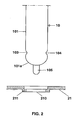
- the cap 21 has four openings 210, through which in each case a leg 101, 102 of a U-shaped glass tube 10th passed through. The legs 101, 102 have sealed ends 101a and form with the cap 21 a permanent melt bond.
- the leg 101 is provided with a pumping stem 105, which is used to evacuate the discharge vessel. 1 serves.
- a pumping stem 105 which is used to evacuate the discharge vessel. 1 serves.
- lamp electrodes 5 which serve to generate a low-pressure gas discharge and each by two protruding from the discharge vessel 1 Lampenstromzu Inserten 6 with are connected to the ballast.
- each aperture 210 of the cap 21 is circular Aperture formed with step-like constricted diameter.
- the diameter of the aperture 210 is slightly larger than the outer diameter of the leg 101 of the U-shaped glass tube 10.
- the aperture 210 has a diameter which is approximately by 0.6 mm smaller than the outer diameter of the leg 101 of the U-shaped Glass tube 10 is. This step-like narrowing of the opening 210 is generated by an annular bead 211 on the inside of the cap 21.
- the leg 101 has two mutually opposite beads 103, 104.
- the cap 21 For fixing the prefabricated, provided with the electrodes 5 and sealed gas-tight Discharge vessel 1 in the cap 21, the cap 21 to a temperature preheated by about 150 degrees Celsius and the legs 101, 102 of the U-shaped Glass tubes 10 of the prefabricated discharge vessel 1 are in the area their ends 101 a, 102 a heated to a temperature of about 350 degrees Celsius.
- the heated legs 101, 102 are, from the outside of the cap 21 ago, in the corresponding openings 210 of the cap introduced.
- Through contact with the hot glass walls of the legs 101, 102 softens and melts the beads 211st forming plastic material.
- the softened and molten plastic material is penetrated by the penetrating into the openings 210 legs 101, 102 of the U-shaped Glass tubes 10 partially displaced.
- the openings 210 in Area of the beads 211 widened, so that their diameter to the outer diameter the leg 101, 102 corresponds.
- the displaced plastic melt forms the solidification a the legs 101, 102 form-fitting surrounding annular Collar 212.
- the legs 101, 102 of the U-shaped glass tubes 10 are introduced so deep into the openings 210 that the beads 103, 104 of the plastic melt are wetted and after the solidification of the plastic melt embedded in the solidified plastic of the beads 211 or the collar 212.
- the mounting of the mounting board 3 and the components 4 of the ballast in the lower part 20 and the attachment of the base sleeve 22 and the contacting thereof with the power supply lines 23, 24 takes place in the usual, known manner. After Assembly of the mounting board 3 and the components 4 of the ballast is consisting of the cap 21 and the discharge vessel 1 unit with the Lower part 20 connected.
- the cap 21 instead of the step-like narrowed openings 210 also have conically narrowed openings.
- the narrowing of the breakthroughs 210 can instead of by beads 211 also with the help of radially into the respective Implementation 210 extending webs 211 'or nubs ( Figure 4) realized become.
- When inserting the heated portions of the discharge vessel 1 are these webs 211 'or pimples melted and the plastic melt is displaced by the penetrating discharge vessel 1. After the freezing of the Plastic melt, the discharge vessel 1 is melted in the cap 21. Further It should be mentioned at this point that already without the beads 103, 104 a fusion bond is achieved with sufficient strength. The beads 103, 104 are only then required if an exceptionally high strength of the connection between Discharge vessel and socket is desired.
- the socket method according to the invention is not based on compact fluorescent lamps limited, but can also, for example, on rod-shaped fluorescent lamps, equipped at both ends with thermoplastic plastic base parts and incandescent lamps whose bases have thermoplastic parts, be applied.
Landscapes
- Engineering & Computer Science (AREA)
- Manufacturing & Machinery (AREA)
- Common Detailed Techniques For Electron Tubes Or Discharge Tubes (AREA)
- Vessels And Coating Films For Discharge Lamps (AREA)
- Lining Or Joining Of Plastics Or The Like (AREA)
- Brushes (AREA)
- Closing Of Containers (AREA)
- Circuit Arrangements For Discharge Lamps (AREA)
- Lighting Device Outwards From Vehicle And Optical Signal (AREA)
Description
- Figur 1
- eine schematische, teilweise geschnittene Seitenansicht eines bevorzugten Ausführungsbeispiels einer erfindungsgemäßen Leuchtstofflampe
- Figur 2
- eine ausschnittweise, schematische und teilweise geschnittene Darstellung des thermoplastischen Kunststoffsockelteils und des Lampengefäßes vor dem Einschmelzungsprozeß
- Figur 3
- eine ausschnittweise, schematische und teilweise Darstellung des thermoplastischen Kunststoffsockelteils und des Lampengefäßes nach dem Einschmelzungsprozeß
- Figur 4
- eine Draufsicht auf eine Durchführung durch das thermoplastische Kunststoffsockelteil gemäß eines zweiten Ausführungsbeispiels der Erfindung
Claims (8)
- Verfahren zur Sockelung einer elektrischen Lampe, die einen mit einem thermoplastischen Kunststoffsockelteil (21) versehenen Lampensockel (2), mindestens ein Lampengefäß (1) und mindestens ein in dem mindestens einen Lampengefäß (1) angeordnetes Leuchtmittel besitzt, wobei das Verfahren zum Einschmelzen des mindestens einen Lampengefäßes (1) in dem Kunststoffsockelteil (21) folgende Verfahrensschritte umfaßt:dadurch gekennzeichnet, daß das Verfahren folgende weiteren Verfahrensschritte umfasst:Erhitzen mindestens eines Abschnittes (101, 102) des mindestens einen Lampengefäßes (1) auf eine Temperatur, die mindestens so hoch wie die Erweichungstemperatur des thermoplastischen Kunststoffsockelteilmaterials und geringer als die Schmelztemperatur des Lampengefäßmaterials ist,Einführen des erhitzten mindestens einen Abschnittes (101, 102) in mindestens eine Aufnahme (210) des Lampensockels (2), wobei das Kunststoffmaterial des Kunststoffsockelteils (21) im Bereich der mindestens einen Aufnahme (210) durch den Kontakt mit dem mindestens einen erhitzten Abschnitt (101, 102) erweicht wird, undErstarrenlassen des erweichten Kunststoffmaterials,Ausstatten des mindestens einen Abschnittes (101, 102) mit mindestens einer Sicke (103, 104),Dimensionieren der mindestens einer Aufnahme (210) derart, dass deren Abmessungen kleiner als die entsprechenden Außenabmessungen des mit der mindestens einen Sicke (103, 104) versehenen Abschnitts (101, 102) sind,Einbetten der mindestens einen Sicke (103, 104) in dem erweichten Kunststoffmaterial während des Einführens des erhitzten mindestens einen Abschnittes (101, 102) in die mindestens eine Aufnahme (210).
- Verfahren nach Anspruch 1, dadurch gekennzeichnet, daß der mindestens eine Abschnitt (101, 102) des mindestens einen Lampengefäßes (1) auf eine Temperatur erhitzt wird, die mindestens so hoch wie die Schmelztemperatur des thermoplastischen Kunststoffsockelteilmaterials ist.
- Verfahren nach Anspruch 1, dadurch gekennzeichnet, daß das Kunststoffsockelteil (21) vor dem Einführen des bzw. der erhitzten Abschnitte (101, 102) des mindestens einen Lampengefäßes (1) in die mindestens eine Aufnahme (210) auf eine Temperatur, die oberhalb der Raumtemperatur und unterhalb der Erweichungstemperatur des Kunststoffsockelteilmaterials liegt, vorgewärmt wird.
- Verfahren nach Anspruch 1, dadurch gekennzeichnet, daß das erweichte Kunststoffmaterial zum Erstarrenlassen gekühlt wird.
- Verfahren nach Anspruch 4, dadurch gekennzeichnet, daß die Kühlung mittels eines Luftstroms erfolgt.
- Verfahren nach Anspruch 1, dadurch gekennzeichnet, daß das verdrängte und erstarrte Kunststoffmaterial einen das mindestens eine Lampengefäß (1) ringförmig umschließenden Kragen (212) formt.
- Verfahren nach Anspruch 1, dadurch gekennzeichnet, daßdas mindestens eine Lampengefäß (1) aus mindestens einem U-förmigen Rohr (10) besteht und der bzw. die Abschnitte die Schenkel (101, 102) des mindestens einen U-förmigen Rohres (10) sind,die mindestens eine Aufnahme (210) als Vertiefung oder Durchbruch in dem Kunststoffsockelteil (21) geformt ist, undder Durchmesser der Vertiefung oder des Durchbruchs (210) kleiner als der Außendurchmesser der Schenkel (101, 102) des mindestens einen U-förmigen Rohres (10) ist.
- Verfahren nach Anspruch 1, dadurch gekennzeichnet, daß das Kunststoffsockelteil (21) als Kappe eines topfartigen Lampensockels (2) geformt ist.
Applications Claiming Priority (3)
| Application Number | Priority Date | Filing Date | Title |
|---|---|---|---|
| DE19928419A DE19928419C1 (de) | 1999-06-23 | 1999-06-23 | Verfahren zur Sockelung einer elektrischen Lampe, Verwendung des Verfahrens zur Sockelung einer Leuchtstofflampe und Leuchtstofflampe |
| DE19928419 | 1999-06-23 | ||
| PCT/DE2000/001935 WO2001001437A1 (de) | 1999-06-23 | 2000-06-14 | Verfahren zur sockelung einer elektrischen lampe |
Publications (2)
| Publication Number | Publication Date |
|---|---|
| EP1105906A1 EP1105906A1 (de) | 2001-06-13 |
| EP1105906B1 true EP1105906B1 (de) | 2005-08-17 |
Family
ID=7912051
Family Applications (1)
| Application Number | Title | Priority Date | Filing Date |
|---|---|---|---|
| EP00949092A Expired - Lifetime EP1105906B1 (de) | 1999-06-23 | 2000-06-14 | Verfahren zur sockelung einer elektrischen lampe |
Country Status (10)
| Country | Link |
|---|---|
| US (1) | US6774564B1 (de) |
| EP (1) | EP1105906B1 (de) |
| JP (1) | JP2003503818A (de) |
| KR (1) | KR100708497B1 (de) |
| CN (1) | CN1191601C (de) |
| AT (1) | ATE302470T1 (de) |
| CA (1) | CA2340136C (de) |
| DE (2) | DE19928419C1 (de) |
| TW (1) | TW473768B (de) |
| WO (1) | WO2001001437A1 (de) |
Families Citing this family (7)
| Publication number | Priority date | Publication date | Assignee | Title |
|---|---|---|---|---|
| US5798693A (en) | 1995-06-07 | 1998-08-25 | Engellenner; Thomas J. | Electronic locating systems |
| DE10163096A1 (de) | 2001-12-20 | 2003-07-03 | Patent Treuhand Ges Fuer Elektrische Gluehlampen Mbh | Kompakte Niederdruckentladungslampe |
| DE10163166A1 (de) | 2001-12-20 | 2003-07-03 | Patent Treuhand Ges Fuer Elektrische Gluehlampen Mbh | Kompakte Niederdruckentladungslampe |
| WO2005024883A1 (ja) | 2003-09-02 | 2005-03-17 | Osram-Melco Ltd. | 蛍光ランプ及び口金 |
| DE102005041719B4 (de) * | 2005-09-01 | 2016-09-29 | Osram Gmbh | Elektrische Lampe mit einem im Sockelinnenteil eingespritzten U-förmigen Haltering |
| DE102007046345A1 (de) * | 2007-09-27 | 2009-04-02 | Osram Gesellschaft mit beschränkter Haftung | Entladungslampe mit einem Gehäuse und einem Entladungsgefäß |
| DE102016207026B4 (de) * | 2016-04-26 | 2022-05-12 | Ledvance Gmbh | Herstellen einer Lampe |
Family Cites Families (14)
| Publication number | Priority date | Publication date | Assignee | Title |
|---|---|---|---|---|
| US3859554A (en) * | 1968-05-13 | 1975-01-07 | Westinghouse Electric Corp | Electric lamp with integral plastic base member |
| DE6753343U (de) * | 1968-08-02 | 1969-04-30 | Patra Patent Treuhand | Elektrische lampe mit kunststoffsockel |
| FR2308197A1 (fr) * | 1975-04-16 | 1976-11-12 | Central Eclairage Lab | Culot moule en matiere synthetique plastique et lampes a incandescence comportant un tel culot |
| DE2634980C3 (de) | 1976-08-04 | 1979-01-25 | Original Hanau Quarzlampen Gmbh, 6450 Hanau | An Halterungen befestigbarer Strahler mit von Sockelhülsen umgebenen kantigen Quetschungen sowie Verfahren und Vorrichtung zum Verbinden der Quetschungen des Strahlers mit den Sockelhülsen |
| DE2721924C3 (de) * | 1977-05-14 | 1979-11-08 | Fritz Wagener Gmbh, 8501 Dietenhofen | Sockelbefestigung für eine Leuchtstofflampe |
| GB2023356B (en) * | 1978-06-19 | 1982-09-22 | Wagener Gmbh F | Fluorescent strip lamp with socket cap |
| CH684786A5 (de) | 1990-04-09 | 1994-12-30 | Bechem Hannelore | Exzenteraktivierte radial schwingende rotierende Werkzeughalter. |
| DE4012684A1 (de) * | 1990-04-20 | 1991-10-24 | Patent Treuhand Ges Fuer Elektrische Gluehlampen Mbh | Kompakte niederdruckentladungslampe |
| DE4014745A1 (de) * | 1990-05-08 | 1991-11-14 | Patent Treuhand Ges Fuer Elektrische Gluehlampen Mbh | Einseitig gesockelte elektrische lampe |
| HU206562B (en) * | 1990-07-19 | 1992-11-30 | Tungsram Reszvenytarsasag | Electric lamp |
| FR2751955B1 (fr) * | 1996-07-31 | 1998-09-04 | Alcatel Fibres Optiques | Fibre optique et son procede de fabrication |
| CN1282988C (zh) * | 1998-11-12 | 2006-11-01 | 皇家菲利浦电子有限公司 | 低压汞蒸汽放电灯 |
| WO2001056350A2 (en) * | 2000-02-01 | 2001-08-09 | Koninklijke Philips Electronics N.V. | Low-pressure mercury vapor discharge lamp |
| DE10223933A1 (de) * | 2001-05-29 | 2002-12-19 | Toshiba Lighting & Technology | Glühentladungslampe, Elektrode hierfür und Leuchtkörper |
-
1999
- 1999-06-23 DE DE19928419A patent/DE19928419C1/de not_active Expired - Fee Related
-
2000
- 2000-06-14 JP JP2001506568A patent/JP2003503818A/ja active Pending
- 2000-06-14 CN CNB008011702A patent/CN1191601C/zh not_active Expired - Fee Related
- 2000-06-14 CA CA002340136A patent/CA2340136C/en not_active Expired - Fee Related
- 2000-06-14 US US09/744,947 patent/US6774564B1/en not_active Expired - Fee Related
- 2000-06-14 KR KR1020017002280A patent/KR100708497B1/ko not_active Expired - Fee Related
- 2000-06-14 EP EP00949092A patent/EP1105906B1/de not_active Expired - Lifetime
- 2000-06-14 WO PCT/DE2000/001935 patent/WO2001001437A1/de not_active Ceased
- 2000-06-14 DE DE50010967T patent/DE50010967D1/de not_active Expired - Lifetime
- 2000-06-14 AT AT00949092T patent/ATE302470T1/de not_active IP Right Cessation
- 2000-06-21 TW TW089112190A patent/TW473768B/zh not_active IP Right Cessation
Also Published As
| Publication number | Publication date |
|---|---|
| DE19928419C1 (de) | 2001-02-22 |
| JP2003503818A (ja) | 2003-01-28 |
| WO2001001437A1 (de) | 2001-01-04 |
| CN1315050A (zh) | 2001-09-26 |
| KR100708497B1 (ko) | 2007-04-16 |
| KR20010072875A (ko) | 2001-07-31 |
| US6774564B1 (en) | 2004-08-10 |
| ATE302470T1 (de) | 2005-09-15 |
| CN1191601C (zh) | 2005-03-02 |
| DE50010967D1 (de) | 2005-09-22 |
| CA2340136C (en) | 2008-12-23 |
| CA2340136A1 (en) | 2001-01-04 |
| EP1105906A1 (de) | 2001-06-13 |
| TW473768B (en) | 2002-01-21 |
Similar Documents
| Publication | Publication Date | Title |
|---|---|---|
| EP0786791B1 (de) | Elektrische Lampe | |
| EP1105906A1 (de) | Verfahren zur sockelung einer elektrischen lampe | |
| DE19618967A1 (de) | Entladungslampe | |
| DE102005051076A1 (de) | Lampe mit Einbaulampe | |
| EP0455884A2 (de) | Einseitig gesockelte elektrische Lampe | |
| EP1679736A2 (de) | Lampe mit Einbaulampe | |
| EP0155672B1 (de) | Einseitig gesockelte Entladungslampe | |
| EP0813229A2 (de) | Verfahren zur Herstellung einer Halogenglühlampe | |
| DE3112821A1 (de) | Elektrische lampe mit einer als quetschung ausgebildeten gefaesseinschmelzung sowie vorrichtung und verfahren zur herstellung | |
| DE69221456T2 (de) | Lampenfuss | |
| DE3320919A1 (de) | Niederdruck-quecksilberdampfentladungslampe und verfahren zu ihrer herstellung | |
| DE2820516A1 (de) | Vorrichtung zur konditionierung von katodenstrahlroehren und verfahren zur ausfuehrung mittels der vorrichtung | |
| DE69010432T2 (de) | Elektrische Lampe. | |
| DE102010002650B4 (de) | Halogenglühlampe für Fahrzeugscheinwerfer | |
| DE3334166A1 (de) | Lampenaufbau | |
| DE19831241A1 (de) | Kunststoffgehäuse- und Sockelaufbau, insbesondere für kompakte Leuchtstofflampen sowie ihre elektronischen Betriebseinheiten | |
| DE19913500A1 (de) | Verfahren zum Verbinden von zwei Kunststoffbauteilen | |
| DE3688319T2 (de) | Elektrische Lampe und Verfahren zur Herstellung dieser Lampe. | |
| DE10210856A1 (de) | Lampe, insbesondere für Kfz-Scheinwerfer | |
| EP0219861A2 (de) | Verfahren zur Herstellung einer einseitig gequetschten Metallhalogenidhochdruckentladungslampe und eine nach diesem Verfahren hergestellte Lampe | |
| DE19715198B4 (de) | Vakuumventil | |
| DE102005041719B4 (de) | Elektrische Lampe mit einem im Sockelinnenteil eingespritzten U-förmigen Haltering | |
| DE69306348T2 (de) | Elektrische Lampe | |
| DE29610921U1 (de) | Elektronische Entladungslampe | |
| EP1196937B1 (de) | Verfahren zum herstellen einer lampe |
Legal Events
| Date | Code | Title | Description |
|---|---|---|---|
| PUAI | Public reference made under article 153(3) epc to a published international application that has entered the european phase |
Free format text: ORIGINAL CODE: 0009012 |
|
| 17P | Request for examination filed |
Effective date: 20001227 |
|
| AK | Designated contracting states |
Kind code of ref document: A1 Designated state(s): AT BE CH CY DE DK ES FI FR GB GR IE IT LI LU MC NL PT SE |
|
| AX | Request for extension of the european patent |
Free format text: AL;LT;LV;MK;RO;SI |
|
| 17Q | First examination report despatched |
Effective date: 20031216 |
|
| GRAP | Despatch of communication of intention to grant a patent |
Free format text: ORIGINAL CODE: EPIDOSNIGR1 |
|
| GRAS | Grant fee paid |
Free format text: ORIGINAL CODE: EPIDOSNIGR3 |
|
| GRAA | (expected) grant |
Free format text: ORIGINAL CODE: 0009210 |
|
| AK | Designated contracting states |
Kind code of ref document: B1 Designated state(s): AT BE CH CY DE DK ES FI FR GB GR IE IT LI LU MC NL PT SE |
|
| PG25 | Lapsed in a contracting state [announced via postgrant information from national office to epo] |
Ref country code: IE Free format text: LAPSE BECAUSE OF FAILURE TO SUBMIT A TRANSLATION OF THE DESCRIPTION OR TO PAY THE FEE WITHIN THE PRESCRIBED TIME-LIMIT Effective date: 20050817 Ref country code: FI Free format text: LAPSE BECAUSE OF FAILURE TO SUBMIT A TRANSLATION OF THE DESCRIPTION OR TO PAY THE FEE WITHIN THE PRESCRIBED TIME-LIMIT Effective date: 20050817 |
|
| REG | Reference to a national code |
Ref country code: GB Ref legal event code: FG4D Free format text: NOT ENGLISH |
|
| REG | Reference to a national code |
Ref country code: CH Ref legal event code: EP |
|
| REG | Reference to a national code |
Ref country code: IE Ref legal event code: FG4D Free format text: LANGUAGE OF EP DOCUMENT: GERMAN |
|
| REF | Corresponds to: |
Ref document number: 50010967 Country of ref document: DE Date of ref document: 20050922 Kind code of ref document: P |
|
| GBT | Gb: translation of ep patent filed (gb section 77(6)(a)/1977) |
Effective date: 20050921 |
|
| PG25 | Lapsed in a contracting state [announced via postgrant information from national office to epo] |
Ref country code: GR Free format text: LAPSE BECAUSE OF FAILURE TO SUBMIT A TRANSLATION OF THE DESCRIPTION OR TO PAY THE FEE WITHIN THE PRESCRIBED TIME-LIMIT Effective date: 20051117 Ref country code: DK Free format text: LAPSE BECAUSE OF FAILURE TO SUBMIT A TRANSLATION OF THE DESCRIPTION OR TO PAY THE FEE WITHIN THE PRESCRIBED TIME-LIMIT Effective date: 20051117 |
|
| PG25 | Lapsed in a contracting state [announced via postgrant information from national office to epo] |
Ref country code: ES Free format text: LAPSE BECAUSE OF FAILURE TO SUBMIT A TRANSLATION OF THE DESCRIPTION OR TO PAY THE FEE WITHIN THE PRESCRIBED TIME-LIMIT Effective date: 20051128 |
|
| REG | Reference to a national code |
Ref country code: SE Ref legal event code: TRGR |
|
| PG25 | Lapsed in a contracting state [announced via postgrant information from national office to epo] |
Ref country code: PT Free format text: LAPSE BECAUSE OF FAILURE TO SUBMIT A TRANSLATION OF THE DESCRIPTION OR TO PAY THE FEE WITHIN THE PRESCRIBED TIME-LIMIT Effective date: 20060117 |
|
| REG | Reference to a national code |
Ref country code: IE Ref legal event code: FD4D |
|
| ET | Fr: translation filed | ||
| PLBE | No opposition filed within time limit |
Free format text: ORIGINAL CODE: 0009261 |
|
| STAA | Information on the status of an ep patent application or granted ep patent |
Free format text: STATUS: NO OPPOSITION FILED WITHIN TIME LIMIT |
|
| PG25 | Lapsed in a contracting state [announced via postgrant information from national office to epo] |
Ref country code: CH Free format text: LAPSE BECAUSE OF NON-PAYMENT OF DUE FEES Effective date: 20060630 Ref country code: MC Free format text: LAPSE BECAUSE OF NON-PAYMENT OF DUE FEES Effective date: 20060630 Ref country code: LI Free format text: LAPSE BECAUSE OF NON-PAYMENT OF DUE FEES Effective date: 20060630 |
|
| 26N | No opposition filed |
Effective date: 20060518 |
|
| REG | Reference to a national code |
Ref country code: CH Ref legal event code: PL |
|
| PG25 | Lapsed in a contracting state [announced via postgrant information from national office to epo] |
Ref country code: AT Free format text: LAPSE BECAUSE OF NON-PAYMENT OF DUE FEES Effective date: 20060614 |
|
| PG25 | Lapsed in a contracting state [announced via postgrant information from national office to epo] |
Ref country code: LU Free format text: LAPSE BECAUSE OF NON-PAYMENT OF DUE FEES Effective date: 20060614 |
|
| PG25 | Lapsed in a contracting state [announced via postgrant information from national office to epo] |
Ref country code: CY Free format text: LAPSE BECAUSE OF FAILURE TO SUBMIT A TRANSLATION OF THE DESCRIPTION OR TO PAY THE FEE WITHIN THE PRESCRIBED TIME-LIMIT Effective date: 20050817 |
|
| REG | Reference to a national code |
Ref country code: DE Ref legal event code: R081 Ref document number: 50010967 Country of ref document: DE Owner name: OSRAM GMBH, DE Free format text: FORMER OWNER: OSRAM GESELLSCHAFT MIT BESCHRAENKTER HAFTUNG, 81543 MUENCHEN, DE Effective date: 20111128 |
|
| PGFP | Annual fee paid to national office [announced via postgrant information from national office to epo] |
Ref country code: NL Payment date: 20120618 Year of fee payment: 13 |
|
| PGFP | Annual fee paid to national office [announced via postgrant information from national office to epo] |
Ref country code: GB Payment date: 20120618 Year of fee payment: 13 Ref country code: SE Payment date: 20120614 Year of fee payment: 13 |
|
| PGFP | Annual fee paid to national office [announced via postgrant information from national office to epo] |
Ref country code: IT Payment date: 20120626 Year of fee payment: 13 |
|
| PGFP | Annual fee paid to national office [announced via postgrant information from national office to epo] |
Ref country code: BE Payment date: 20120710 Year of fee payment: 13 Ref country code: DE Payment date: 20120820 Year of fee payment: 13 Ref country code: FR Payment date: 20120711 Year of fee payment: 13 |
|
| REG | Reference to a national code |
Ref country code: DE Ref legal event code: R081 Ref document number: 50010967 Country of ref document: DE Owner name: OSRAM GMBH, DE Free format text: FORMER OWNER: OSRAM AG, 81543 MUENCHEN, DE Effective date: 20130205 |
|
| REG | Reference to a national code |
Ref country code: DE Ref legal event code: R081 Ref document number: 50010967 Country of ref document: DE Owner name: OSRAM GMBH, DE Free format text: FORMER OWNER: OSRAM GMBH, 81543 MUENCHEN, DE Effective date: 20130822 |
|
| BERE | Be: lapsed |
Owner name: *PATENT-TREUHAND-G.- FUR ELEKTRISCHE GLUHLAMPEN M. Effective date: 20130630 |
|
| REG | Reference to a national code |
Ref country code: NL Ref legal event code: V1 Effective date: 20140101 |
|
| PG25 | Lapsed in a contracting state [announced via postgrant information from national office to epo] |
Ref country code: SE Free format text: LAPSE BECAUSE OF NON-PAYMENT OF DUE FEES Effective date: 20130615 |
|
| REG | Reference to a national code |
Ref country code: SE Ref legal event code: EUG |
|
| GBPC | Gb: european patent ceased through non-payment of renewal fee |
Effective date: 20130614 |
|
| REG | Reference to a national code |
Ref country code: DE Ref legal event code: R119 Ref document number: 50010967 Country of ref document: DE Effective date: 20140101 |
|
| REG | Reference to a national code |
Ref country code: FR Ref legal event code: ST Effective date: 20140228 |
|
| PG25 | Lapsed in a contracting state [announced via postgrant information from national office to epo] |
Ref country code: BE Free format text: LAPSE BECAUSE OF NON-PAYMENT OF DUE FEES Effective date: 20130630 |
|
| PG25 | Lapsed in a contracting state [announced via postgrant information from national office to epo] |
Ref country code: NL Free format text: LAPSE BECAUSE OF NON-PAYMENT OF DUE FEES Effective date: 20140101 Ref country code: DE Free format text: LAPSE BECAUSE OF NON-PAYMENT OF DUE FEES Effective date: 20140101 Ref country code: GB Free format text: LAPSE BECAUSE OF NON-PAYMENT OF DUE FEES Effective date: 20130614 |
|
| PG25 | Lapsed in a contracting state [announced via postgrant information from national office to epo] |
Ref country code: FR Free format text: LAPSE BECAUSE OF NON-PAYMENT OF DUE FEES Effective date: 20130701 Ref country code: IT Free format text: LAPSE BECAUSE OF NON-PAYMENT OF DUE FEES Effective date: 20130614 |