EP1105673B1 - A light fiber and a method for producing the same - Google Patents
A light fiber and a method for producing the same Download PDFInfo
- Publication number
- EP1105673B1 EP1105673B1 EP99931917A EP99931917A EP1105673B1 EP 1105673 B1 EP1105673 B1 EP 1105673B1 EP 99931917 A EP99931917 A EP 99931917A EP 99931917 A EP99931917 A EP 99931917A EP 1105673 B1 EP1105673 B1 EP 1105673B1
- Authority
- EP
- European Patent Office
- Prior art keywords
- light
- clad
- core
- diffusive
- reflective
- Prior art date
- Legal status (The legal status is an assumption and is not a legal conclusion. Google has not performed a legal analysis and makes no representation as to the accuracy of the status listed.)
- Expired - Lifetime
Links
- 239000000835 fiber Substances 0.000 title claims description 81
- 238000004519 manufacturing process Methods 0.000 title claims description 5
- 239000000463 material Substances 0.000 claims description 21
- 238000001125 extrusion Methods 0.000 claims description 15
- 239000012260 resinous material Substances 0.000 claims description 12
- 230000002093 peripheral effect Effects 0.000 claims description 6
- 239000011162 core material Substances 0.000 description 52
- GWEVSGVZZGPLCZ-UHFFFAOYSA-N Titan oxide Chemical compound O=[Ti]=O GWEVSGVZZGPLCZ-UHFFFAOYSA-N 0.000 description 47
- 239000011347 resin Substances 0.000 description 27
- 229920005989 resin Polymers 0.000 description 27
- 239000004408 titanium dioxide Substances 0.000 description 23
- 229920009441 perflouroethylene propylene Polymers 0.000 description 22
- 238000000605 extraction Methods 0.000 description 18
- 238000000034 method Methods 0.000 description 16
- 229920000642 polymer Polymers 0.000 description 16
- 239000010419 fine particle Substances 0.000 description 13
- 239000000203 mixture Substances 0.000 description 12
- PEDCQBHIVMGVHV-UHFFFAOYSA-N Glycerine Chemical compound OCC(O)CO PEDCQBHIVMGVHV-UHFFFAOYSA-N 0.000 description 8
- 229920004428 Neoflon® PCTFE Polymers 0.000 description 8
- 239000002243 precursor Substances 0.000 description 8
- 230000000052 comparative effect Effects 0.000 description 7
- XEKOWRVHYACXOJ-UHFFFAOYSA-N Ethyl acetate Chemical compound CCOC(C)=O XEKOWRVHYACXOJ-UHFFFAOYSA-N 0.000 description 6
- 229920006362 Teflon® Polymers 0.000 description 6
- 238000000149 argon plasma sintering Methods 0.000 description 6
- 229920001577 copolymer Polymers 0.000 description 6
- 238000005259 measurement Methods 0.000 description 6
- 239000011230 binding agent Substances 0.000 description 5
- 239000008188 pellet Substances 0.000 description 5
- 239000000243 solution Substances 0.000 description 5
- BQCIDUSAKPWEOX-UHFFFAOYSA-N 1,1-Difluoroethene Chemical compound FC(F)=C BQCIDUSAKPWEOX-UHFFFAOYSA-N 0.000 description 4
- 229920000178 Acrylic resin Polymers 0.000 description 4
- 239000004925 Acrylic resin Substances 0.000 description 4
- SOGAXMICEFXMKE-UHFFFAOYSA-N Butylmethacrylate Chemical compound CCCCOC(=O)C(C)=C SOGAXMICEFXMKE-UHFFFAOYSA-N 0.000 description 4
- YCKRFDGAMUMZLT-UHFFFAOYSA-N Fluorine atom Chemical compound [F] YCKRFDGAMUMZLT-UHFFFAOYSA-N 0.000 description 4
- 229920006367 Neoflon Polymers 0.000 description 4
- VYPSYNLAJGMNEJ-UHFFFAOYSA-N Silicium dioxide Chemical compound O=[Si]=O VYPSYNLAJGMNEJ-UHFFFAOYSA-N 0.000 description 4
- 239000011248 coating agent Substances 0.000 description 4
- 238000000576 coating method Methods 0.000 description 4
- 229920000840 ethylene tetrafluoroethylene copolymer Polymers 0.000 description 4
- 229910052731 fluorine Inorganic materials 0.000 description 4
- 239000011737 fluorine Substances 0.000 description 4
- 235000011187 glycerol Nutrition 0.000 description 4
- 229910052754 neon Inorganic materials 0.000 description 4
- GKAOGPIIYCISHV-UHFFFAOYSA-N neon atom Chemical compound [Ne] GKAOGPIIYCISHV-UHFFFAOYSA-N 0.000 description 4
- 239000007787 solid Substances 0.000 description 4
- BFKJFAAPBSQJPD-UHFFFAOYSA-N tetrafluoroethene Chemical group FC(F)=C(F)F BFKJFAAPBSQJPD-UHFFFAOYSA-N 0.000 description 4
- LYCAIKOWRPUZTN-UHFFFAOYSA-N Ethylene glycol Chemical compound OCCO LYCAIKOWRPUZTN-UHFFFAOYSA-N 0.000 description 3
- 239000004698 Polyethylene Substances 0.000 description 3
- 239000012790 adhesive layer Substances 0.000 description 3
- 239000000284 extract Substances 0.000 description 3
- 229920001684 low density polyethylene Polymers 0.000 description 3
- 239000004702 low-density polyethylene Substances 0.000 description 3
- 239000011259 mixed solution Substances 0.000 description 3
- 238000002156 mixing Methods 0.000 description 3
- 239000013308 plastic optical fiber Substances 0.000 description 3
- -1 polyethylene Polymers 0.000 description 3
- 229920000573 polyethylene Polymers 0.000 description 3
- 238000006116 polymerization reaction Methods 0.000 description 3
- NOBYOEQUFMGXBP-UHFFFAOYSA-N (4-tert-butylcyclohexyl) (4-tert-butylcyclohexyl)oxycarbonyloxy carbonate Chemical compound C1CC(C(C)(C)C)CCC1OC(=O)OOC(=O)OC1CCC(C(C)(C)C)CC1 NOBYOEQUFMGXBP-UHFFFAOYSA-N 0.000 description 2
- HWSSEYVMGDIFMH-UHFFFAOYSA-N 2-[2-[2-(2-methylprop-2-enoyloxy)ethoxy]ethoxy]ethyl 2-methylprop-2-enoate Chemical compound CC(=C)C(=O)OCCOCCOCCOC(=O)C(C)=C HWSSEYVMGDIFMH-UHFFFAOYSA-N 0.000 description 2
- WDQMWEYDKDCEHT-UHFFFAOYSA-N 2-ethylhexyl 2-methylprop-2-enoate Chemical compound CCCCC(CC)COC(=O)C(C)=C WDQMWEYDKDCEHT-UHFFFAOYSA-N 0.000 description 2
- XKRFYHLGVUSROY-UHFFFAOYSA-N Argon Chemical compound [Ar] XKRFYHLGVUSROY-UHFFFAOYSA-N 0.000 description 2
- IJGRMHOSHXDMSA-UHFFFAOYSA-N Atomic nitrogen Chemical compound N#N IJGRMHOSHXDMSA-UHFFFAOYSA-N 0.000 description 2
- VGGSQFUCUMXWEO-UHFFFAOYSA-N Ethene Chemical compound C=C VGGSQFUCUMXWEO-UHFFFAOYSA-N 0.000 description 2
- FAPWRFPIFSIZLT-UHFFFAOYSA-M Sodium chloride Chemical compound [Na+].[Cl-] FAPWRFPIFSIZLT-UHFFFAOYSA-M 0.000 description 2
- 229920006356 Teflon™ FEP Polymers 0.000 description 2
- QVQLCTNNEUAWMS-UHFFFAOYSA-N barium oxide Chemical compound [Ba]=O QVQLCTNNEUAWMS-UHFFFAOYSA-N 0.000 description 2
- 239000006185 dispersion Substances 0.000 description 2
- 230000000694 effects Effects 0.000 description 2
- HCDGVLDPFQMKDK-UHFFFAOYSA-N hexafluoropropylene Chemical group FC(F)=C(F)C(F)(F)F HCDGVLDPFQMKDK-UHFFFAOYSA-N 0.000 description 2
- 230000000977 initiatory effect Effects 0.000 description 2
- 239000010410 layer Substances 0.000 description 2
- 239000000178 monomer Substances 0.000 description 2
- 239000005304 optical glass Substances 0.000 description 2
- 239000003505 polymerization initiator Substances 0.000 description 2
- 239000000843 powder Substances 0.000 description 2
- YMRMDGSNYHCUCL-UHFFFAOYSA-N 1,2-dichloro-1,1,2-trifluoroethane Chemical compound FC(Cl)C(F)(F)Cl YMRMDGSNYHCUCL-UHFFFAOYSA-N 0.000 description 1
- SMZOUWXMTYCWNB-UHFFFAOYSA-N 2-(2-methoxy-5-methylphenyl)ethanamine Chemical compound COC1=CC=C(C)C=C1CCN SMZOUWXMTYCWNB-UHFFFAOYSA-N 0.000 description 1
- YEVQZPWSVWZAOB-UHFFFAOYSA-N 2-(bromomethyl)-1-iodo-4-(trifluoromethyl)benzene Chemical compound FC(F)(F)C1=CC=C(I)C(CBr)=C1 YEVQZPWSVWZAOB-UHFFFAOYSA-N 0.000 description 1
- GOXQRTZXKQZDDN-UHFFFAOYSA-N 2-Ethylhexyl acrylate Chemical compound CCCCC(CC)COC(=O)C=C GOXQRTZXKQZDDN-UHFFFAOYSA-N 0.000 description 1
- NIXOWILDQLNWCW-UHFFFAOYSA-N 2-Propenoic acid Natural products OC(=O)C=C NIXOWILDQLNWCW-UHFFFAOYSA-N 0.000 description 1
- 101100008044 Caenorhabditis elegans cut-1 gene Proteins 0.000 description 1
- 239000000853 adhesive Substances 0.000 description 1
- 230000001070 adhesive effect Effects 0.000 description 1
- 239000002313 adhesive film Substances 0.000 description 1
- PNEYBMLMFCGWSK-UHFFFAOYSA-N aluminium oxide Inorganic materials [O-2].[O-2].[O-2].[Al+3].[Al+3] PNEYBMLMFCGWSK-UHFFFAOYSA-N 0.000 description 1
- 239000007864 aqueous solution Substances 0.000 description 1
- 229910052786 argon Inorganic materials 0.000 description 1
- 239000002801 charged material Substances 0.000 description 1
- 238000005034 decoration Methods 0.000 description 1
- 238000007865 diluting Methods 0.000 description 1
- 239000004205 dimethyl polysiloxane Substances 0.000 description 1
- 235000013870 dimethyl polysiloxane Nutrition 0.000 description 1
- KPUWHANPEXNPJT-UHFFFAOYSA-N disiloxane Chemical class [SiH3]O[SiH3] KPUWHANPEXNPJT-UHFFFAOYSA-N 0.000 description 1
- 239000000975 dye Substances 0.000 description 1
- 150000002148 esters Chemical class 0.000 description 1
- QHSJIZLJUFMIFP-UHFFFAOYSA-N ethene;1,1,2,2-tetrafluoroethene Chemical compound C=C.FC(F)=C(F)F QHSJIZLJUFMIFP-UHFFFAOYSA-N 0.000 description 1
- 229920001038 ethylene copolymer Polymers 0.000 description 1
- 238000011156 evaluation Methods 0.000 description 1
- 229940052308 general anesthetics halogenated hydrocarbons Drugs 0.000 description 1
- 150000008282 halocarbons Chemical class 0.000 description 1
- 238000010438 heat treatment Methods 0.000 description 1
- 229930195733 hydrocarbon Natural products 0.000 description 1
- 150000002430 hydrocarbons Chemical class 0.000 description 1
- 238000005286 illumination Methods 0.000 description 1
- 239000011261 inert gas Substances 0.000 description 1
- 229910017053 inorganic salt Inorganic materials 0.000 description 1
- 239000007788 liquid Substances 0.000 description 1
- 239000011344 liquid material Substances 0.000 description 1
- 229940057995 liquid paraffin Drugs 0.000 description 1
- CPLXHLVBOLITMK-UHFFFAOYSA-N magnesium oxide Inorganic materials [Mg]=O CPLXHLVBOLITMK-UHFFFAOYSA-N 0.000 description 1
- 239000000395 magnesium oxide Substances 0.000 description 1
- AXZKOIWUVFPNLO-UHFFFAOYSA-N magnesium;oxygen(2-) Chemical compound [O-2].[Mg+2] AXZKOIWUVFPNLO-UHFFFAOYSA-N 0.000 description 1
- 229910001507 metal halide Inorganic materials 0.000 description 1
- 150000005309 metal halides Chemical class 0.000 description 1
- 229910052757 nitrogen Inorganic materials 0.000 description 1
- 239000003921 oil Substances 0.000 description 1
- 239000002245 particle Substances 0.000 description 1
- 238000005191 phase separation Methods 0.000 description 1
- 239000000049 pigment Substances 0.000 description 1
- 229920000435 poly(dimethylsiloxane) Polymers 0.000 description 1
- 229920001200 poly(ethylene-vinyl acetate) Polymers 0.000 description 1
- 229920003229 poly(methyl methacrylate) Polymers 0.000 description 1
- 229920000728 polyester Polymers 0.000 description 1
- 229920000570 polyether Polymers 0.000 description 1
- 239000004926 polymethyl methacrylate Substances 0.000 description 1
- 238000002360 preparation method Methods 0.000 description 1
- 239000010453 quartz Substances 0.000 description 1
- 230000005855 radiation Effects 0.000 description 1
- 238000011160 research Methods 0.000 description 1
- 239000011342 resin composition Substances 0.000 description 1
- 239000004576 sand Substances 0.000 description 1
- 238000007789 sealing Methods 0.000 description 1
- 229920002545 silicone oil Polymers 0.000 description 1
- 239000011343 solid material Substances 0.000 description 1
- 239000002904 solvent Substances 0.000 description 1
- 150000005846 sugar alcohols Polymers 0.000 description 1
- 238000012546 transfer Methods 0.000 description 1
- 238000002834 transmittance Methods 0.000 description 1
- 239000012780 transparent material Substances 0.000 description 1
- HQUQLFOMPYWACS-UHFFFAOYSA-N tris(2-chloroethyl) phosphate Chemical compound ClCCOP(=O)(OCCCl)OCCCl HQUQLFOMPYWACS-UHFFFAOYSA-N 0.000 description 1
- XLYOFNOQVPJJNP-UHFFFAOYSA-N water Substances O XLYOFNOQVPJJNP-UHFFFAOYSA-N 0.000 description 1
Images
Classifications
-
- G—PHYSICS
- G02—OPTICS
- G02B—OPTICAL ELEMENTS, SYSTEMS OR APPARATUS
- G02B6/00—Light guides; Structural details of arrangements comprising light guides and other optical elements, e.g. couplings
-
- G—PHYSICS
- G02—OPTICS
- G02B—OPTICAL ELEMENTS, SYSTEMS OR APPARATUS
- G02B6/00—Light guides; Structural details of arrangements comprising light guides and other optical elements, e.g. couplings
- G02B6/0001—Light guides; Structural details of arrangements comprising light guides and other optical elements, e.g. couplings specially adapted for lighting devices or systems
- G02B6/0005—Light guides; Structural details of arrangements comprising light guides and other optical elements, e.g. couplings specially adapted for lighting devices or systems the light guides being of the fibre type
- G02B6/001—Light guides; Structural details of arrangements comprising light guides and other optical elements, e.g. couplings specially adapted for lighting devices or systems the light guides being of the fibre type the light being emitted along at least a portion of the lateral surface of the fibre
Definitions
- Discharge tubes such as fluorescent lamp emit a visible light of a particular wavelength region, they are ordinarily used in the application fields for lighting. In the case where the discharge tubes are a neon bulb, they are used to demonstrate an advertisement or decoration or the like in the form of the so-called neon sign.
- the discharge tubes are luminescent with the application of electric voltage. Generally, the discharge tubes generate heat. In such a case, it is necessary to use the discharge tubes with due regard to an electric leakage and the generation of heat. For example, the use of discharge tubes is substantially impossible for under-water lighting or demonstration.
- a light-emitting device comprising a light source located at a distance from the area illuminated therewith has attracted attention to achieve the lighting and demonstration as set forth above.
- a light fiber is installed in the vicinity of an area to be illuminated, away from the light source, so as to give the illumination of a desired light.
- the light fibers comprise a core in the central portion and a clad having a refractive index lower than that of the core on the periphery of the core. A light can be injected into one end and transmitted to the other end of thus configured light fiber.
- a light fiber of directional side light extraction type which can extract a light from the sidewall.
- Those light fibers of directional side light extraction type can extract parts of a light from the sidewall through the clad to the outside, when the light is injected into one end and transmitted to the other.
- the clad is made of two different parts one of which is composed of a vinylidene fluoride-based copolymer comprising 50 to 90% by mole of vinylidene fluoride and 10 to 50% by mole of tetrafluoroethylene, and another part comprises at least one of the other polymers having a refractive index higher than that of the vinylidene fluoride-based copolymer, preferably a polymer which is the same as or close to the core-forming polymer.
- the clad and core are compatible each other on the interfacial boundary between them. In the interface between the core and the clad which are compatible, the light can not transmit in the core with total reflection, but scatters about within the clad; as a consequence, the light is extracted to the outside.
- JP-A-10-142428 discloses a light-illuminating rod capable of extracting a light from the sidewall to a specific direction.
- This light-illuminating rod is basically provided with a flexible rod member serving as a core in the central portion and a transparent clad layer having a refractive index lower than that of the core and bonded to the outer periphery of the flexible rod member.
- a light diffusive and reflective film comprising a light transmitting polymer in which light diffusive and reflective fine particles are dispersed is present locally therebetween along the longitudinal direction of the rod member.
- This light diffusive and reflective film reflects at least parts of a light injected from one end of the light-illuminating rod member, diffusing and reflecting it to the outside from the radiation surface of the clad in the front of said light diffusive and reflective film.
- JP-B-4-70604, and the like disclose inventions relating to light-illuminating rods comprising the inflexible rod members.
- a hardly flexible material such as quartz glass or optical glass is used as a rod member in those inventions.
- the two different polymers forming the clad are incompatible each other and caused a phase separation. Those two incompatible and phase-separated polymers have as little a refractive index difference as about 0.25 at most. In this light-illuminating plastic optical fiber, therefore, the clad cannot exhibit a light diffusive and reflective effect good enough to extract a highly bright light in a specific direction from the sidewall efficiently if an ordinary light source is used.
- the light diffusive and reflective film disclosed in JP-A-10-142428 is formed by applying a coating material containing a light transmitting polymer and light diffusive and reflective fine particles to a rod member.
- the light diffusive and reflective film is a light diffusive, reflective and adhesive film, it is laid directly on the rod member.
- those light diffusive and reflective films have a thickness of from 10 ⁇ m to 110 ⁇ m at most in the case of commercialized products because of various restrictive factors at the time of the production.
- at least parts of light which is injected into the flexible rod member from one end of the light-illuminating rod is leaked through those light diffusive and reflective films to the outside. Therefore, there is a fear that a highly bright light can hardly be extracted in a specific direction from the sidewall in high efficiency.
- a heat-shrinkable type material may hardly be used. If it is used, a rod member having a cross section substantially in the shape of a circle can not be produced since the light diffusive and reflective film portion is partially protruded unlike in the case of the ordinary light-illuminating rods.
- the light-illuminating rods are generally mounted on a commercially available holder-rail having a reflective surface on the internal surface, such as U rail (white) manufactured by Sumitomo-3M, with the intentions to improve the directivity of the lights to be extracted to the outside or the like. Since the holder-rail is made to have the cross section in the shape of a circle which is the most popular cross section among the light-illuminating rods, it appears likely that the light-illuminating rods having a thick and protruded light diffusive and reflective film portion are not housed surely in the said holder-rail.
- a light diffusive and reflective portion such as a light diffusive and reflective film from, for example, a material obtained by mixing and dispersing light diffusive and reflective fine particles into a clad-forming resinous material; and said portion is formed at the inner periphery of a clad by co-extruding a resinous material only, and a mixture, for example, obtained by mixing light diffusive and reflective fine particles with a resinous material to disperse said fine particles therein at the time of forming a clad.
- the present invention has been completed on the basis of those findings.
- a light fiber comprising a core and a clad having a refractive index lower than that of the core on the periphery of the core, characterized in that the light fiber has a light diffusive and reflective portion formed by co-extrusion at least on the inner periphery of the clad;
- a light fiber characterized in that the diffusive and reflective portion comes into contact with the core;
- the light diffusive and reflective portion has a thickness extending at least to the vicinity of outer periphery of the clad in a direction perpendicular to the longitudinal direction from the clad
- a light fiber characterized in that the diffusive and reflective portion is formed a linear shape or a band-like shape along the longitudinal direction of the clad; seventhly, there is provided a light fiber, characterized in that the light diffusive and reflective portion is formed along the peripheral direction of the clad, and eighthly, there is provided a method for producing a light fiber which comprises a core, a clad covering said core and a light diffusive and reflective portion, characterized in that a resinous material having a refractive index lower than that of the core-forming, light transmitting material, and a light diffusive and reflective material are co-extruded so as to form a light diffusive and reflective portion at least on the inner periphery of the clad.
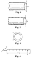
- Fig. 1 shows one embodiment of light fibers according to the present invention.
- the light fiber comprises the so-called core in the central portion and a clad having a refractive index lower than that of the core on the periphery thereof.
- the core is formed from a solid mass of light transmitting materials such as quartz glass, optical glass; and polymers and it has a refractive index of 1.4 to 2.0.
- the core is preferably made of a flexible material described in Paragraph 0014 of JP-A-10-142428, for example, such as acrylic resins, ethylene-vinyl acetate copolymers and the like. The relevant descriptions of said laid-open publication are incorporated herein by reference. More preferably, the core is made of an acrylic resin having a refractive index of about 1.5.
- a solid material is generally used as a core material, however, a liquid material is also usable.
- the liquid core material include aqueous solutions of an inorganic salt; polyhydric alcohols such as ethylene glycol, glycerin and the like; silicone oils such as polydimethyl siloxane, polyphenylmethyl siloxane and the like; polyethers; polyesters; hydrocarbons such as liquid paraffin; halo-genated hydrocarbons such as trifluoroethylenechloride oil; phosphoric esters such as tri(chloroethyl)phosphate, trioctylphosphate and the like; and polymer solutions prepared by diluting various polymers with appropriate solvents and the like.
- the maximum thickness of the film is equal to the thickness of the clad. Since the clad has typically a thickness of from 100 to 800 ⁇ m, the light diffusive and reflective film is able to have a thickness of from 100 to 800 ⁇ m.
- the clad of the present invention can be equipped with a light diffusive and reflective film being thicker than that of the conventional ones, thereby the leakage of a light through the light diffusive and reflective film is prevented.
- the light fiber according to the present embodiment can efficiently diffuse and reflect a light which is transmitting within the core in a forward direction of light diffusive and reflective film. As a consequence, a comparatively strong light is extracted only in a specific direction from the sidewall of the light fibers.
- the light diffusive and reflective film is made of a light diffusive and reflective material obtained by incorporating light scattering fine particles which are explained hereinafter into a resinous material such as an FEP, ETFE resin and the like or polyethylene (PE) having a refractive index of about 1.34 to about 1.51 so as to disperse them uniformly therein.
- Said a light diffusive and reflective film is formed by co-extruding a preparation produced by adding to said resinous material the light scattering fine particles in an amount so as to be contained from 0.3 to 30% by weight.
- a light extracting from the sidewall of the light fiber can be quantitatively adjusted in proportion to the refractive index of resin and the amount of light scattering fine particles incorporated therein.
- the light diffusive and reflective film can be formed being protruded into the inner portion of the core from the inner periphery surface of the clad, as shown in Fig. 3. Furthermore, the light diffusive and reflective film may be colored by incorporating a pigment or a dyestuff thereinto.
- the clad described as above is made, in the following way, by means of co-extrusion molding by extruding two or more materials with two or more extruders.
- a fluorine-based resin for example, Teflon@ FEP 100-J pellet manufactured by Du Pont in a predetermined amount and a fluorine-based resin composition containing the light scattering fine particles previously mixed and dispersed therein, for example, Neoflon®FEP NP20WH resin pellet containing 3% by weight of titanium dioxide and manufactured by Daikin Kogyo in a predetermined amount are prepared, respectively.
- a fluorine-based resin for example, Teflon@ FEP 100-J pellet manufactured by Du Pont in a predetermined amount
- a fluorine-based resin composition containing the light scattering fine particles previously mixed and dispersed therein for example, Neoflon®FEP NP20WH resin pellet containing 3% by weight of titanium dioxide and manufactured by Daikin Kogyo in a predetermined amount are prepared, respectively.
- a material obtained by adding a predetermined amount of light scattering fine particles to an appropriate clad-forming resinous material so as to mix and disperse them therein.
- each of those pellets is respectively charged into two extruders prepared in advance, and extruded into a die, whereby a tubular clad having a light diffusive and reflective film mentioned above is molded integrally.
- a step of coating an light diffusive and reflective film or adhering an adhesive light diffusive and reflective film both of which are discussed in the section of the prior art is not called for.
- the core can be produced, for example, in the following way. There is prepared firstly a mixed monomer solution containing a predetermined amount of 2-ethylhexyl-methacrylate, a predetermined amount of n-butylmethacrylate and a predetermined amount of triethyleneglycoldimethacrylate. Thereafter, bis (4-t-butylcyclohexyl) peroxydicarbonate is added to the mixed solution as a polymerization initiator to prepare a core precursor. Then, said clad is bent into the shape of U, and the core precursor is injected from one end into within the clad. Thereafter, a solid core is formed so as to provide a light fiber of directional side light extraction type by heating the resultant up to the polymerization initiation temperature.
- the core precursor is heated serially from the bottom to the top of the U-shaped clad.
- the core precursor may come into contact with an inert gas such as nitrogen or argon so as to apply a pressure thereon.
- the core precursor may be heated as a whole, together with the clad, for a predetermined period of time to make the core precursor react completely.
- Teflon® FEP 100-J pellets having a refractive index of about 1.34 and manufactured by Du Pont, and Neoflon® FEP NP20WH resin pellets comprising a binder composed of FEP having a refractive index of about 1.34 and 3% by weight of titanium dioxide and manufactured by Daikin Kogyo are charged, respectively into two extruders previously prepared.
- charged materials were co-extruded into a die so as to give a tubular clad having an outside diameter of about 12 mm and a thickness of about 0.8 mm.
- the clad was found to be provided with a light diffusive and reflective film formed along the longitudinal direction of the clad; said film having a width of about 13 mm and a thickness of about 0.8 mm and containing 3% by weight of titanium dioxide.
- a light fiber was prepared by repeating the procedure of Example 1, except that a clad having an outside diameter of about 9 mm and a thickness of about 0.7 mm was produced by co-extrusion molding. In this case, a light diffusive and reflective film was formed in the clad along the longitudinal direction of the clad; said film having a width of about 10 mm and a thickness of about 0.7 mm and containing 3% by weight of titanium dioxide.
- a light fiber was prepared by repeating the procedure of Example 1, except that a clad having an outside diameter of about 18 mm and a thickness of about 0.8 mm was produced by co-extrusion molding. In this case, a light diffusive and reflective film was formed in the clad along the longitudinal direction of the clad; said film having a width of about 20 mm and a thickness of about 0.8 mm and containing 3% by weight of titanium dioxide.
- a clad having an outside diameter of about 12 mm and a thickness of about 0.8 mm was prepared by charging said Teflon® FEP 100-J resin, and TFC SM-413 white resin containing a binder comprised of FEP having a refractive index of about 1.34 and 20% by weight of titanium dioxide and manufactured by Dai-nichi Seika Kogyo into 2 extruders of Example 1, respectively.
- a light diffusive and reflective film was formed in the clad; said film being as thin as about 0.1 mm, running along the longitudinal direction of the clad, having a width of about 13 mm, and containing 20% by weight of titanium dioxide.
- a light fiber was prepared by repeating the procedure of Example 6, except that a clad having an outside diameter of about 18 mm and a thickness of about 0.8 mm was produced by charging Neoflon® ETFE EP521 resin manufactured by Daikin Kogyo having a refractive index of about 1.43 and AFC SM-412 white resin comprising a binder composed of ETFE having a refractive index of about 1.43 and 30% by weight of titanium dioxide, respectively into 2 extruders and subjecting said materials to co-extrusion molding.
- a light diffusive and reflective film was formed in the clad; said film being as thin as about 0.5 mm, running along the longitudinal direction of the clad, having a width of about 20 mm, and containing 30% by weight of titanium dioxide.
- a light fiber was prepared by repeating the procedure of Example 6, except that a clad having an outside diameter of about 18 mm and a thickness of about 0.9 mm was produced by charging a mixture of 10 kg of Teflon FEP 100-J resin and 0.1 kg of Neoflon FEP NP20WH resin manufactured by Daikin Kogyo, and the above-mentioned Neoflon FEP NP20WH manufactured by Daikin Kogyo, respectively into 2 extruders; and subjecting said materials to co-extrusion molding.
- a light diffusive and reflective film was formed in the clad; said film being as thin as about 0.5 mm, running along the longitudinal direction of the clad, having a width of about 22 mm and containing 3% by weight of titanium dioxide.
- a light fiber was prepared by repeating the procedure of Example 6, except that a clad having an outside diameter of about 9 mm and a thickness of about 0.7 mm was obtained by charging Teflon FEP 100-J resin and Neoflon FEP NP20WH resin, respectively, into 2 extruders, and subjecting said materials to co-extrusion molding.
- a light diffusive and reflective film was formed in the clad; said film running along the longitudinal direction of the clad, having a width of about 21 mm and a thickness of about 0.7 mm and containing 3% by weight of titanium dioxide.
- the brightness was measured in the way as shown in Fig. 4.
- One end of the respective light fibers according to said Examples and Comparative Example was respectively connected with a metal halide lamp LBM130H manufactured by Sumitomo-3M as the light source.
- a Minolta brightness meter CS-100 (not depicted) was disposed at a predetermined distance of 0.1 to 10 m from the light source to measure the brightness. Thereupon, the brightness meter was positioned at the site 60 cm away from the light fiber. The light leaked from the sidewall opposite to the site of sticking the light diffusive and reflective film to the core was also measured by using same measuring method at the predetermined distance.
- the results of the brightness measurement was shown in Tables 1 and 2. According to Tables 1 and 2, it was found that the light fiber of Comparative Example leaked, through the light diffusive and reflective portion, light in an extent similar to that extracted when the light fiber extracted light in the forward direction by means of the light diffusive and reflective portion. On the contrary, in all the light fibers of said Examples, the brightness of the light leaked through the light diffusive and reflective portion was found to be, at most, 25% or lower of the brightness of the total light when the light fiber extracted it in the forward direction from the light diffusive and reflective portion.
- the light fibers of the present invention could reduce the light leakage through the light diffusive and reflective portion, extracting a comparatively strong light only in a specific direction from the sidewall.
- Those light fibers can be used for the application fields wherein a light having a high brightness is required, such as for example, as a substitute for neon sign.
- the ones wherein the illuminance in an area illuminated therewith are important, other than those wherein the brightness thereof is important as a yardstick for the performance of the light fiber, like the case with neon sign to take a look at directly with eyes.
Landscapes
- Physics & Mathematics (AREA)
- General Physics & Mathematics (AREA)
- Optics & Photonics (AREA)
- Light Guides In General And Applications Therefor (AREA)
- Optical Fibers, Optical Fiber Cores, And Optical Fiber Bundles (AREA)
- Non-Portable Lighting Devices Or Systems Thereof (AREA)
- Spinning Methods And Devices For Manufacturing Artificial Fibers (AREA)
Applications Claiming Priority (3)
| Application Number | Priority Date | Filing Date | Title |
|---|---|---|---|
| JP10226212A JP2000056136A (ja) | 1998-08-10 | 1998-08-10 | ライトファイバおよびその製造方法 |
| JP22621298 | 1998-08-10 | ||
| PCT/US1999/014429 WO2000009943A1 (en) | 1998-08-10 | 1999-06-25 | A light fiber and a method for producing the same |
Publications (2)
| Publication Number | Publication Date |
|---|---|
| EP1105673A1 EP1105673A1 (en) | 2001-06-13 |
| EP1105673B1 true EP1105673B1 (en) | 2004-04-14 |
Family
ID=16841662
Family Applications (1)
| Application Number | Title | Priority Date | Filing Date |
|---|---|---|---|
| EP99931917A Expired - Lifetime EP1105673B1 (en) | 1998-08-10 | 1999-06-25 | A light fiber and a method for producing the same |
Country Status (7)
| Country | Link |
|---|---|
| EP (1) | EP1105673B1 (enExample) |
| JP (2) | JP2000056136A (enExample) |
| KR (1) | KR20010072361A (enExample) |
| AU (1) | AU762580B2 (enExample) |
| BR (1) | BR9912880A (enExample) |
| DE (1) | DE69916462T2 (enExample) |
| WO (1) | WO2000009943A1 (enExample) |
Cited By (3)
| Publication number | Priority date | Publication date | Assignee | Title |
|---|---|---|---|---|
| DE102008009137A1 (de) * | 2008-02-14 | 2009-08-27 | Schott Ag | Seitenemittierende Stufenindexfaser |
| DE102008009139A1 (de) * | 2008-02-14 | 2009-08-27 | Schott Ag | Seitenemittierende Stufenindexfaser |
| DE102008034791B4 (de) | 2008-07-25 | 2022-01-20 | Schott Ag | Preformen und Verfahren zur Herstellung von seitenemittierenden Stufenindexfasern |
Families Citing this family (9)
| Publication number | Priority date | Publication date | Assignee | Title |
|---|---|---|---|---|
| EP1336875A1 (de) * | 2002-02-16 | 2003-08-20 | Preh-Werke GmbH & Co. KG | Lichtleiter |
| US20070258085A1 (en) * | 2006-05-02 | 2007-11-08 | Robbins Michael D | Substrate illumination and inspection system |
| KR20040049572A (ko) * | 2002-12-06 | 2004-06-12 | 삼성전자주식회사 | 발산형 플라스틱 광섬유를 이용한 액정표시장치용백라이트 유닛 |
| JP2006317844A (ja) * | 2005-05-16 | 2006-11-24 | Three M Innovative Properties Co | 側面発光型光ファイバー及び発光装置 |
| WO2009100834A1 (de) | 2008-02-14 | 2009-08-20 | Schott Ag | Seitenemittierende stufenindexfaser |
| JP5885196B2 (ja) * | 2011-08-18 | 2016-03-15 | フクビ化学工業株式会社 | 光ファイバ型線状発光体の製造方法、及び光ファイバ型線状発光体 |
| ITRM20120387A1 (it) * | 2012-08-03 | 2014-02-04 | Headway Srl | "guida di luce" |
| KR101971692B1 (ko) * | 2012-12-17 | 2019-04-25 | 엘지이노텍 주식회사 | 차량용 조명유닛 |
| JP6287421B2 (ja) * | 2014-03-24 | 2018-03-07 | 株式会社デンソー | ライトガイド部材、ライトガイド部材用のアタッチメント、イルミネーション装置 |
Family Cites Families (9)
| Publication number | Priority date | Publication date | Assignee | Title |
|---|---|---|---|---|
| JPS60118806A (ja) * | 1983-11-30 | 1985-06-26 | Agency Of Ind Science & Technol | 照明具 |
| JPH01109303A (ja) * | 1987-10-23 | 1989-04-26 | Hitachi Ltd | 表示用光フアイバ |
| JPH0470604A (ja) * | 1990-07-06 | 1992-03-05 | Hitachi Cable Ltd | 合成樹脂光伝送体の製造方法 |
| JPH0514619A (ja) * | 1991-07-04 | 1993-01-22 | Minolta Camera Co Ltd | 画像読取装置 |
| JPH06118244A (ja) * | 1992-10-02 | 1994-04-28 | Mitsubishi Rayon Co Ltd | 照光プラスチック光ファイバ |
| JPH10142428A (ja) * | 1996-11-07 | 1998-05-29 | Minnesota Mining & Mfg Co <3M> | 光照射ロッド |
| JP2000039517A (ja) * | 1998-07-24 | 2000-02-08 | Bridgestone Corp | 光伝送チューブ及びその製造方法 |
| JP2000039521A (ja) * | 1998-07-24 | 2000-02-08 | Bridgestone Corp | 光伝送チューブ及びその製造方法 |
| JP2000039520A (ja) * | 1998-07-24 | 2000-02-08 | Bridgestone Corp | 光伝送チューブ及びその製造方法 |
-
1998
- 1998-08-10 JP JP10226212A patent/JP2000056136A/ja active Pending
-
1999
- 1999-06-25 WO PCT/US1999/014429 patent/WO2000009943A1/en not_active Ceased
- 1999-06-25 KR KR1020017001708A patent/KR20010072361A/ko not_active Abandoned
- 1999-06-25 JP JP2000565347A patent/JP2002525643A/ja active Pending
- 1999-06-25 BR BR9912880-2A patent/BR9912880A/pt active Search and Examination
- 1999-06-25 DE DE69916462T patent/DE69916462T2/de not_active Expired - Fee Related
- 1999-06-25 AU AU48328/99A patent/AU762580B2/en not_active Ceased
- 1999-06-25 EP EP99931917A patent/EP1105673B1/en not_active Expired - Lifetime
Cited By (5)
| Publication number | Priority date | Publication date | Assignee | Title |
|---|---|---|---|---|
| DE102008009137A1 (de) * | 2008-02-14 | 2009-08-27 | Schott Ag | Seitenemittierende Stufenindexfaser |
| DE102008009139A1 (de) * | 2008-02-14 | 2009-08-27 | Schott Ag | Seitenemittierende Stufenindexfaser |
| DE102008009137B4 (de) * | 2008-02-14 | 2017-09-21 | Schott Ag | Seitenemittierende Stufenindexfaser |
| DE102008009139B4 (de) | 2008-02-14 | 2021-09-23 | Schott Ag | Seitenemittierende Stufenindexfaser, Faserbündel und Flächengebilde und deren Verwendungen sowie Preformen und Verfahren zu deren Herstellung |
| DE102008034791B4 (de) | 2008-07-25 | 2022-01-20 | Schott Ag | Preformen und Verfahren zur Herstellung von seitenemittierenden Stufenindexfasern |
Also Published As
| Publication number | Publication date |
|---|---|
| AU762580B2 (en) | 2003-06-26 |
| EP1105673A1 (en) | 2001-06-13 |
| DE69916462D1 (de) | 2004-05-19 |
| JP2002525643A (ja) | 2002-08-13 |
| AU4832899A (en) | 2000-03-06 |
| DE69916462T2 (de) | 2005-03-24 |
| WO2000009943A1 (en) | 2000-02-24 |
| KR20010072361A (ko) | 2001-07-31 |
| BR9912880A (pt) | 2001-05-08 |
| JP2000056136A (ja) | 2000-02-25 |
Similar Documents
| Publication | Publication Date | Title |
|---|---|---|
| US6563993B1 (en) | Light fiber and a method for producing the same | |
| EP1125152B1 (en) | Light fibers and methods of producing the same | |
| EP1105673B1 (en) | A light fiber and a method for producing the same | |
| EP1221628B1 (en) | Optical transmission tube, method for making it and linear illuminant system | |
| JP2001521200A (ja) | 光ファイバからの光の拡散反射を有する物品 | |
| CA2571929C (en) | Light guide, method and apparatus for manufacturing the same, and illuminating system having the same | |
| US20050074216A1 (en) | Side-illumination type optical fiber | |
| CA2430494A1 (en) | Side-illumination type optical fiber | |
| KR20010013806A (ko) | 자체 발광 역반사성 시이트 및 이것의 제조 방법 | |
| EP1250611A2 (en) | Reflector, method for the production of reflector, and internal-lighting display device | |
| JP3998502B2 (ja) | 視線誘導照明装置 | |
| EP1376003A1 (en) | Linear light emitter and method of manufacturing the light emitter | |
| JPH11281819A (ja) | 光ファイバーおよび発光装置 | |
| KR100988626B1 (ko) | 광 파이프 및 이를 구비한 조명장치 | |
| JP2544134B2 (ja) | 平面状光源を得る板状光伝送体 | |
| JP2002196150A (ja) | 光導入発光体 | |
| JP2000039517A (ja) | 光伝送チューブ及びその製造方法 | |
| JP2000338330A (ja) | 線状発光体及びその製造方法 | |
| EP3557292A1 (en) | Static semi-retro-reflective displays | |
| JP2000039520A (ja) | 光伝送チューブ及びその製造方法 | |
| JP2001108834A (ja) | 光ファイバ及びそれを用いた発光表示装置 | |
| JP2001108856A (ja) | 光ファイバ及びその製造方法 | |
| AU2002226907A1 (en) | Side-illumination type optical fiber | |
| MXPA99011358A (en) | Self light-emitting retroreflective sheet and method for producing the same |
Legal Events
| Date | Code | Title | Description |
|---|---|---|---|
| PUAI | Public reference made under article 153(3) epc to a published international application that has entered the european phase |
Free format text: ORIGINAL CODE: 0009012 |
|
| 17P | Request for examination filed |
Effective date: 20010301 |
|
| AK | Designated contracting states |
Kind code of ref document: A1 Designated state(s): DE FR GB |
|
| GRAH | Despatch of communication of intention to grant a patent |
Free format text: ORIGINAL CODE: EPIDOS IGRA |
|
| GRAS | Grant fee paid |
Free format text: ORIGINAL CODE: EPIDOSNIGR3 |
|
| GRAA | (expected) grant |
Free format text: ORIGINAL CODE: 0009210 |
|
| AK | Designated contracting states |
Kind code of ref document: B1 Designated state(s): DE FR GB |
|
| PG25 | Lapsed in a contracting state [announced via postgrant information from national office to epo] |
Ref country code: FR Free format text: LAPSE BECAUSE OF FAILURE TO SUBMIT A TRANSLATION OF THE DESCRIPTION OR TO PAY THE FEE WITHIN THE PRESCRIBED TIME-LIMIT Effective date: 20040414 |
|
| REG | Reference to a national code |
Ref country code: GB Ref legal event code: FG4D |
|
| REF | Corresponds to: |
Ref document number: 69916462 Country of ref document: DE Date of ref document: 20040519 Kind code of ref document: P |
|
| PG25 | Lapsed in a contracting state [announced via postgrant information from national office to epo] |
Ref country code: GB Free format text: LAPSE BECAUSE OF NON-PAYMENT OF DUE FEES Effective date: 20040714 |
|
| PLBE | No opposition filed within time limit |
Free format text: ORIGINAL CODE: 0009261 |
|
| STAA | Information on the status of an ep patent application or granted ep patent |
Free format text: STATUS: NO OPPOSITION FILED WITHIN TIME LIMIT |
|
| GBPC | Gb: european patent ceased through non-payment of renewal fee |
Effective date: 20040714 |
|
| EN | Fr: translation not filed | ||
| 26N | No opposition filed |
Effective date: 20050117 |
|
| PGFP | Annual fee paid to national office [announced via postgrant information from national office to epo] |
Ref country code: DE Payment date: 20080731 Year of fee payment: 10 |
|
| PG25 | Lapsed in a contracting state [announced via postgrant information from national office to epo] |
Ref country code: DE Free format text: LAPSE BECAUSE OF NON-PAYMENT OF DUE FEES Effective date: 20100101 |