EP1103206A1 - Höhenverstellbares Fussystem für Möbelausrüstung und Verfahren zu dessen Montage - Google Patents
Höhenverstellbares Fussystem für Möbelausrüstung und Verfahren zu dessen Montage Download PDFInfo
- Publication number
- EP1103206A1 EP1103206A1 EP00403249A EP00403249A EP1103206A1 EP 1103206 A1 EP1103206 A1 EP 1103206A1 EP 00403249 A EP00403249 A EP 00403249A EP 00403249 A EP00403249 A EP 00403249A EP 1103206 A1 EP1103206 A1 EP 1103206A1
- Authority
- EP
- European Patent Office
- Prior art keywords
- worm
- wheel
- screw
- foot
- housing
- Prior art date
- Legal status (The legal status is an assumption and is not a legal conclusion. Google has not performed a legal analysis and makes no representation as to the accuracy of the status listed.)
- Withdrawn
Links
Images

Classifications
-
- A—HUMAN NECESSITIES
- A47—FURNITURE; DOMESTIC ARTICLES OR APPLIANCES; COFFEE MILLS; SPICE MILLS; SUCTION CLEANERS IN GENERAL
- A47B—TABLES; DESKS; OFFICE FURNITURE; CABINETS; DRAWERS; GENERAL DETAILS OF FURNITURE
- A47B91/00—Feet for furniture in general
- A47B91/02—Adjustable feet
- A47B91/022—Adjustable feet using screw means
- A47B91/028—Means for rotational adjustment on a non-rotational foot
Definitions
- the invention relates to a height-adjustable foot system remotely controllable for furniture equipment, especially for built-in household appliance.
- the object of the invention is to remedy this drawback by simplifying the adjustable feet system.
- a foot system adjustable in remote controllable height for furniture equipment especially for built-in or built-in household appliance, of the type comprising a foot threaded spindle screwed into a thread integral with the chassis the equipment and driven in rotation by a toothed wheel which is linked to it in rotation, said wheel being part of a wheel transmission mechanism and worm, said worm being rotated by a device remote control, the system being characterized in that said wheel has an upper collar with a diameter greater than that of the bottom of toothing of the wheel and in that said worm is arranged and maintained in a chassis housing close to the thread so that it come to cooperate with said wheel and keep it in axial translation by by pressing the collar on the screw.
- the retention in place of the toothed wheel is ensured by the single worm, the toothed wheel not having to transmit the weight of the device, and the worm is housed directly in a housing of the device chassis.
- the invention provides a mounting method extremely simple of this system.
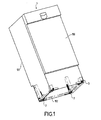
- Figure 1 a general view of an apparatus household, here a dishwasher, equipped according to the invention.
- Device 1 has a front face 100, a rear face 101, a frame 102 and rear legs adjustable in height 2 controlled from the front using a rod 3, as will be seen in more detail in the following description.
- FIG. 2 is an exploded isometric perspective view of the rear right of the chassis alone with the remote adjustable foot system thanks to a control rod 3.
- the foot 2 has a pin threaded 20 resting on the ground by a base 22 which can be provided with a wafer (not shown) ensuring sliding in rotation on the ground.
- the threaded pin 20 can be screwed into a female thread 103 secured to the chassis 102.
- the spindle also comprises at least one longitudinal groove 21, the role will be specified later.
- the spindle is rotated by a toothed wheel 5 making part of a worm and wheel transmission mechanism whose screw 4 is controlled by the rod 3.
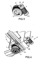
- FIG. 3 shows this mechanism.
- the wheel 5 has a upper flange 50 whose diameter is greater than that of the bottom of gear teeth.
- the toothed wheel is pierced with an axial hole for the passage of the threaded spindle 20, this hole being provided with lugs 51 which must engage sliding in the grooves 21 of the spindle so as to ensure the free sliding of the wheel on the spindle while ensuring a connection in rotation to control the rotation of the spindle.
- the worm screw 4 the thread of which cooperates with the teeth of the wheel 5, is terminated symmetrically by two at its ends identical cylindrical rings 41 and 43 with an axial housing, 42 for the ring 41 or for each of the two rings 41 and 43, comprising a part frustoconical entry followed by a part ensuring the connection of shape, for example by a square or hexagonal shape, with the end of the control rod 3.
- the frusto-conical part guides the rod, which is removable, when introduced into the screw.
- FIG 4 is shown more precisely the adjustment system installed, element 4.1 representing the worm before mounting.
- element 4.1 representing the worm before mounting.
- the screw 4 is held in place downwards by a tongue 104 secured to the chassis. It is held in axial translation by a stop 105 retaining the ring end of the screw.
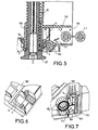
- the tongue 104 has an interior shape matching the cylindrical shape of the screw but in fact only needs a contact according to a longitudinal line positioned to prevent escape of the screw to the bottom. That is, the width of the opening between the toothed wheel and the edge of the tongue 104 must be less than the diameter of the screw, as see it better in Figure 5.
- FIG. 5 is a sectional view of the adjustable foot system according to the invention.
- the foot 2 with the threaded pin 20 and the base 22, the internal thread 103 in the frame 102, the toothed wheel 5 and the screw endless 4 in their operating position after assembly.
- the screw end 4 is disposed in a housing 111 of the chassis 102.
- This housing is delimited by the tongue 104 and a flexible rib 6 secured to the chassis, whose ground plane substantially by the axis of the screw 4 to prohibit the ascent.
- the worm 4 in taken with the toothing of the wheel 5 prevents it from falling out thanks to the support of the flange 50 on the screw itself, without any other device for holding or intermediate piece.
- the assembly of the system is very easy by maintaining the wheel 5 against the internal thread 103 thanks to the base 22 of the screwed foot 2 completely on the thread, presenting the screw in the opening 110 of the chassis housing (positions 4.I then 4.II) then pushing the screw against the resistance of the rib 6 which, being flexible, disappears up to position 60 before returning to its normal position by locking the auger in his accommodation.
- Figures 6 and 7 show views of the housing in the chassis 102, respectively according to arrows A and B in Figure 4. We can note the position of the rib 6 and the tongue 104.
- the housing 111 is completed by the stops 105 and 106 for the rings 41 and 43 of the worm, stops which prevent any axial translation of the screw ( Figure 7).
- adjustable foot system according to the invention can also be applied to any furniture equipment (cupboards, etc.) requiring an upgrade.
Landscapes
- Transmission Devices (AREA)
- Legs For Furniture In General (AREA)
Applications Claiming Priority (2)
| Application Number | Priority Date | Filing Date | Title |
|---|---|---|---|
| FR9914931A FR2801479A1 (fr) | 1999-11-26 | 1999-11-26 | Systeme de pied reglable en hauteur pour equipement mobilier et procede pour son montage |
| FR9914931 | 1999-11-26 |
Publications (1)
| Publication Number | Publication Date |
|---|---|
| EP1103206A1 true EP1103206A1 (de) | 2001-05-30 |
Family
ID=9552594
Family Applications (1)
| Application Number | Title | Priority Date | Filing Date |
|---|---|---|---|
| EP00403249A Withdrawn EP1103206A1 (de) | 1999-11-26 | 2000-11-21 | Höhenverstellbares Fussystem für Möbelausrüstung und Verfahren zu dessen Montage |
Country Status (2)
| Country | Link |
|---|---|
| EP (1) | EP1103206A1 (de) |
| FR (1) | FR2801479A1 (de) |
Cited By (7)
| Publication number | Priority date | Publication date | Assignee | Title |
|---|---|---|---|---|
| WO2004085908A2 (de) * | 2003-03-26 | 2004-10-07 | Leica Microsystems Wetzlar Gmbh | Vorrichtung zur höhenverstellung und träger für optische systeme mit vorrichtungen zur höhenverstellung |
| WO2005115199A1 (en) * | 2004-05-24 | 2005-12-08 | Leonardo S.R.L. | Levelling system for a piece of furniture |
| WO2009068399A1 (de) * | 2007-11-29 | 2009-06-04 | BSH Bosch und Siemens Hausgeräte GmbH | Haushaltsgerät mit einer höhenverstellvorrichtung für einen gerätefuss |
| WO2014177227A1 (en) * | 2013-05-03 | 2014-11-06 | Arcelik Anonim Sirketi | Household appliance having improved height profile adjustable feet |
| ITMI20131072A1 (it) * | 2013-06-27 | 2014-12-28 | Leonardo Srl | Sistema di livellamento per mobili |
| CN111820627A (zh) * | 2020-07-31 | 2020-10-27 | 安徽省汉帮家具制造有限公司 | 一种基于指纹识别的多功能智能文件柜 |
| RU2786042C2 (ru) * | 2018-09-26 | 2022-12-16 | Леонардо С.р.Л. | Улучшенное крепление для мебельных ножек, регулируемых по высоте |
Citations (4)
| Publication number | Priority date | Publication date | Assignee | Title |
|---|---|---|---|---|
| US1387390A (en) * | 1920-10-05 | 1921-08-09 | Joseph Warren | Adjustable table-leg |
| US1417639A (en) * | 1921-03-19 | 1922-05-30 | Daniel L Sterner | Table leveler |
| DE9421684U1 (de) * | 1993-04-30 | 1996-08-14 | Forster Ag Hermann | Einbau-Haushaltgerät mit Nivellierorganen |
| DE19606460A1 (de) * | 1996-02-21 | 1997-08-28 | Bosch Siemens Hausgeraete | Höhenverstellvorrichtung für einen Stellfuß eines Haushaltgerätes |
-
1999
- 1999-11-26 FR FR9914931A patent/FR2801479A1/fr active Pending
-
2000
- 2000-11-21 EP EP00403249A patent/EP1103206A1/de not_active Withdrawn
Patent Citations (4)
| Publication number | Priority date | Publication date | Assignee | Title |
|---|---|---|---|---|
| US1387390A (en) * | 1920-10-05 | 1921-08-09 | Joseph Warren | Adjustable table-leg |
| US1417639A (en) * | 1921-03-19 | 1922-05-30 | Daniel L Sterner | Table leveler |
| DE9421684U1 (de) * | 1993-04-30 | 1996-08-14 | Forster Ag Hermann | Einbau-Haushaltgerät mit Nivellierorganen |
| DE19606460A1 (de) * | 1996-02-21 | 1997-08-28 | Bosch Siemens Hausgeraete | Höhenverstellvorrichtung für einen Stellfuß eines Haushaltgerätes |
Cited By (14)
| Publication number | Priority date | Publication date | Assignee | Title |
|---|---|---|---|---|
| WO2004085908A2 (de) * | 2003-03-26 | 2004-10-07 | Leica Microsystems Wetzlar Gmbh | Vorrichtung zur höhenverstellung und träger für optische systeme mit vorrichtungen zur höhenverstellung |
| WO2004085908A3 (de) * | 2003-03-26 | 2005-01-13 | Leica Microsystems | Vorrichtung zur höhenverstellung und träger für optische systeme mit vorrichtungen zur höhenverstellung |
| WO2005115199A1 (en) * | 2004-05-24 | 2005-12-08 | Leonardo S.R.L. | Levelling system for a piece of furniture |
| WO2009068399A1 (de) * | 2007-11-29 | 2009-06-04 | BSH Bosch und Siemens Hausgeräte GmbH | Haushaltsgerät mit einer höhenverstellvorrichtung für einen gerätefuss |
| US8220760B2 (en) | 2007-11-29 | 2012-07-17 | Bsh Bosch Und Siemens Hausgeraete Gmbh | Household appliance having a height-adjusting device for an appliance pedestal |
| CN101868165B (zh) * | 2007-11-29 | 2013-01-23 | Bsh博世和西门子家用器具有限公司 | 具有用于器具支腿的高度调节装置的家用器具 |
| WO2014177227A1 (en) * | 2013-05-03 | 2014-11-06 | Arcelik Anonim Sirketi | Household appliance having improved height profile adjustable feet |
| US9572429B2 (en) | 2013-05-03 | 2017-02-21 | Arcelik Anonim Sirketi | Household appliance having improved height profile adjustable feet |
| ITMI20131072A1 (it) * | 2013-06-27 | 2014-12-28 | Leonardo Srl | Sistema di livellamento per mobili |
| EP2839761A1 (de) * | 2013-06-27 | 2015-02-25 | Leonardo S.r.L. | Nivelliersystem für Möbel |
| EP3488734A1 (de) * | 2013-06-27 | 2019-05-29 | LEONARDO S.r.l. | Nivelliersystem für möbel |
| RU2786042C2 (ru) * | 2018-09-26 | 2022-12-16 | Леонардо С.р.Л. | Улучшенное крепление для мебельных ножек, регулируемых по высоте |
| CN111820627A (zh) * | 2020-07-31 | 2020-10-27 | 安徽省汉帮家具制造有限公司 | 一种基于指纹识别的多功能智能文件柜 |
| CN111820627B (zh) * | 2020-07-31 | 2021-11-02 | 安徽省汉帮家具制造有限公司 | 一种基于指纹识别的多功能智能文件柜 |
Also Published As
| Publication number | Publication date |
|---|---|
| FR2801479A1 (fr) | 2001-06-01 |
Similar Documents
| Publication | Publication Date | Title |
|---|---|---|
| EP1103206A1 (de) | Höhenverstellbares Fussystem für Möbelausrüstung und Verfahren zu dessen Montage | |
| EP0715383B1 (de) | Anordnung zur Befestigung eines elektrischen Gerätes an einer Tragschiene | |
| FR3008896A1 (fr) | Systeme de fixation reglable pour planche de glisse et planche equipee d’un tel systeme | |
| EP3239447B1 (de) | Motorisierte antriebsvorrichtung eines schiebetors, und heimschliessanlage, die eine solche vorrichtung umfasst | |
| FR2960582A1 (fr) | Ensemble de porte | |
| EP0429336A1 (de) | Behälterverschluss, insbesondere Tankverschluss für Kraftfahrzeug | |
| EP0560034A1 (de) | Montagevorrichtung für Zubehörseite auf Skis | |
| FR2956257A1 (fr) | Organe de pre-assemblage d'un chassis d'appareil electrique sur une goulotte electrique, appareil electrique comportant un tel organe de pre -assemblage, et procede de fixation d'un tel organe de pre-assemblage sur le chassis d'un tel appareil electrique | |
| FR3103642A1 (fr) | Appareillage à support d’appareillage basculant | |
| FR2518216A1 (fr) | Dispositif pour la fixation rapide d'un appareil sur une plate-forme support | |
| EP0885764A1 (de) | Kraftstofftankdeckel für Kraftfahrzeug | |
| FR2781837A1 (fr) | Dispositif de montage pour moteur de volet roulant | |
| FR2806531A1 (fr) | Dispositif de fixation d'une batterie d'accumulateurs | |
| FR2555526A1 (fr) | Mecanisme de commande pour siege de vehicule | |
| FR3073164A1 (fr) | Dispositif de pre-assemblage pour machine de sertissage de raccord a bague coupante, et machine de sertissage le comprenant | |
| FR2772819A1 (fr) | Semelle de reglage d'une gache de serrure de vehicule automobile | |
| EP3400858B1 (de) | Befestigungsvorrichtung von heizkörperzubehörteilen | |
| FR2666369A1 (fr) | Ferrure pour une fenetre, une porte, ou similaire. | |
| FR2764555A1 (fr) | Bouchon de reservoir de carburant pour vehicule | |
| EP2022921B1 (de) | Befestigungsvorrichtung für einen Mitnehmer einer Fensterscheibe bestehend aus Schraubenmuttern und Schrauben | |
| FR2748512A1 (fr) | Gache destinee a une serrure notamment d'ascenseur | |
| FR2759727A3 (fr) | Dispositif de fermeture pour porte | |
| FR2678352A1 (fr) | Systeme d'attache rapide d'un appareil de prise de vues sur un trepied. | |
| EP0225222B1 (de) | Elektrisches Gerät mit verbessertem Zusammenbau | |
| FR2500879A1 (fr) | Fermeture a declic pour portes d'armoires ou elements analogues |
Legal Events
| Date | Code | Title | Description |
|---|---|---|---|
| PUAI | Public reference made under article 153(3) epc to a published international application that has entered the european phase |
Free format text: ORIGINAL CODE: 0009012 |
|
| AK | Designated contracting states |
Kind code of ref document: A1 Designated state(s): DE ES FR GB IT |
|
| AX | Request for extension of the european patent |
Free format text: AL;LT;LV;MK;RO;SI |
|
| 17P | Request for examination filed |
Effective date: 20010514 |
|
| AKX | Designation fees paid |
Free format text: DE ES FR GB IT |
|
| STAA | Information on the status of an ep patent application or granted ep patent |
Free format text: STATUS: THE APPLICATION IS DEEMED TO BE WITHDRAWN |
|
| 18D | Application deemed to be withdrawn |
Effective date: 20030603 |