EP1102354A2 - Dispositif pour contacter des conducteurs à feuille, en particulier d'un module solaire - Google Patents
Dispositif pour contacter des conducteurs à feuille, en particulier d'un module solaire Download PDFInfo
- Publication number
- EP1102354A2 EP1102354A2 EP00310224A EP00310224A EP1102354A2 EP 1102354 A2 EP1102354 A2 EP 1102354A2 EP 00310224 A EP00310224 A EP 00310224A EP 00310224 A EP00310224 A EP 00310224A EP 1102354 A2 EP1102354 A2 EP 1102354A2
- Authority
- EP
- European Patent Office
- Prior art keywords
- housing
- conductor
- foil
- connecting region
- contact
- Prior art date
- Legal status (The legal status is an assumption and is not a legal conclusion. Google has not performed a legal analysis and makes no representation as to the accuracy of the status listed.)
- Granted
Links
- 239000004020 conductor Substances 0.000 title claims abstract description 79
- 239000011888 foil Substances 0.000 title claims abstract description 45
- 238000007789 sealing Methods 0.000 claims description 23
- 150000001875 compounds Chemical class 0.000 claims description 6
- 239000011521 glass Substances 0.000 description 18
- 239000000463 material Substances 0.000 description 4
- 239000007921 spray Substances 0.000 description 4
- XLYOFNOQVPJJNP-UHFFFAOYSA-N water Substances O XLYOFNOQVPJJNP-UHFFFAOYSA-N 0.000 description 4
- 239000003292 glue Substances 0.000 description 2
- 238000003780 insertion Methods 0.000 description 2
- 230000037431 insertion Effects 0.000 description 2
- 230000002093 peripheral effect Effects 0.000 description 2
- CBENFWSGALASAD-UHFFFAOYSA-N Ozone Chemical compound [O-][O+]=O CBENFWSGALASAD-UHFFFAOYSA-N 0.000 description 1
- 230000006978 adaptation Effects 0.000 description 1
- 230000001419 dependent effect Effects 0.000 description 1
- 238000011161 development Methods 0.000 description 1
- 230000018109 developmental process Effects 0.000 description 1
- 230000000694 effects Effects 0.000 description 1
- 238000009434 installation Methods 0.000 description 1
- 239000012528 membrane Substances 0.000 description 1
- 238000000034 method Methods 0.000 description 1
- 230000005855 radiation Effects 0.000 description 1
Images


Classifications
-
- H—ELECTRICITY
- H01—ELECTRIC ELEMENTS
- H01R—ELECTRICALLY-CONDUCTIVE CONNECTIONS; STRUCTURAL ASSOCIATIONS OF A PLURALITY OF MUTUALLY-INSULATED ELECTRICAL CONNECTING ELEMENTS; COUPLING DEVICES; CURRENT COLLECTORS
- H01R12/00—Structural associations of a plurality of mutually-insulated electrical connecting elements, specially adapted for printed circuits, e.g. printed circuit boards [PCB], flat or ribbon cables, or like generally planar structures, e.g. terminal strips, terminal blocks; Coupling devices specially adapted for printed circuits, flat or ribbon cables, or like generally planar structures; Terminals specially adapted for contact with, or insertion into, printed circuits, flat or ribbon cables, or like generally planar structures
- H01R12/50—Fixed connections
- H01R12/59—Fixed connections for flexible printed circuits, flat or ribbon cables or like structures
- H01R12/62—Fixed connections for flexible printed circuits, flat or ribbon cables or like structures connecting to rigid printed circuits or like structures
-
- H—ELECTRICITY
- H02—GENERATION; CONVERSION OR DISTRIBUTION OF ELECTRIC POWER
- H02S—GENERATION OF ELECTRIC POWER BY CONVERSION OF INFRARED RADIATION, VISIBLE LIGHT OR ULTRAVIOLET LIGHT, e.g. USING PHOTOVOLTAIC [PV] MODULES
- H02S40/00—Components or accessories in combination with PV modules, not provided for in groups H02S10/00 - H02S30/00
- H02S40/30—Electrical components
- H02S40/34—Electrical components comprising specially adapted electrical connection means to be structurally associated with the PV module, e.g. junction boxes
-
- H—ELECTRICITY
- H01—ELECTRIC ELEMENTS
- H01R—ELECTRICALLY-CONDUCTIVE CONNECTIONS; STRUCTURAL ASSOCIATIONS OF A PLURALITY OF MUTUALLY-INSULATED ELECTRICAL CONNECTING ELEMENTS; COUPLING DEVICES; CURRENT COLLECTORS
- H01R13/00—Details of coupling devices of the kinds covered by groups H01R12/70 or H01R24/00 - H01R33/00
- H01R13/46—Bases; Cases
- H01R13/52—Dustproof, splashproof, drip-proof, waterproof, or flameproof cases
- H01R13/5205—Sealing means between cable and housing, e.g. grommet
- H01R13/5208—Sealing means between cable and housing, e.g. grommet having at least two cable receiving openings
-
- Y—GENERAL TAGGING OF NEW TECHNOLOGICAL DEVELOPMENTS; GENERAL TAGGING OF CROSS-SECTIONAL TECHNOLOGIES SPANNING OVER SEVERAL SECTIONS OF THE IPC; TECHNICAL SUBJECTS COVERED BY FORMER USPC CROSS-REFERENCE ART COLLECTIONS [XRACs] AND DIGESTS
- Y02—TECHNOLOGIES OR APPLICATIONS FOR MITIGATION OR ADAPTATION AGAINST CLIMATE CHANGE
- Y02E—REDUCTION OF GREENHOUSE GAS [GHG] EMISSIONS, RELATED TO ENERGY GENERATION, TRANSMISSION OR DISTRIBUTION
- Y02E10/00—Energy generation through renewable energy sources
- Y02E10/50—Photovoltaic [PV] energy
Definitions
- the invention relates to an apparatus for making contact with foil conductors, in particular those of a solar module, having a housing, a first connecting region for connecting to the foil conductors and a second connecting region with at least one contact for connecting to at least one plug connector.
- foil conductors that are usually guided between two glass sheets.
- the foil conductors emerge through a hole in the two glass sheets and it is necessary to produce a connection, which is sealed against water spray, at this round connection point. It is normal in this case for the thickness of the glass sheets with the hole to vary, for example, between three and five millimetres.
- the diaphragm cover is connected securely to the housing. This is achieved by the diaphragm cover being joined to the housing by a strap hinge. As the diaphragm cover is made of a flexible material, different from the material of the housing, the hinge is connected to the housing via a latching connection.
- the diaphragm cover simultaneously seals and closes the housing of the apparatus. This is achieved as the diaphragm cover has a sealing lip which engages in a corresponding groove of the housing.
- the diaphragm cover is easy to open. This is achieved by an opening aid that is provided into which a tool can be inserted so that the cover can be easily opened by lever action of the tool.
- protection is provided to prevent touching of the current-carrying contacts. This is achieved through an intermediate cover that is provided and arranged between the housing and the cover to cover the conductor rails. It is also particularly advantageous that the terminal areas for receiving electronic modules are accessible when the intermediate cover is inserted.
- the housing is filled to the intermediate cover with sealing compound.
- the intermediate cover can not be detached from the housing after sealing. This is achieved by the latching hook of the intermediate cover by which this intermediate cover is fastened to the housing so that it is also sealed. This measure ensures that once the apparatus has been fastened to a solar panel no further manipulation is possible.
- sealing compound easy to insert. This is achieved by a sealing funnel that is provided on the intermediate cover. It is also particularly advantageous that the foil conductors are very easy to fasten. This is achieved in that the contact regions of the conductor rails have clamping springs which enable the foil conductors to be clamped between the clamping springs and the conductor rail.
- a centring ring is provided on the first connecting region for centring the housing in the recess of the upper glass plate of the solar module.
- a seal is provided between the solar module and the connecting region of the housing to assure a seal against water spray and enable adaptation for various glass thicknesses.
- a seal of this type can be achieved by means of a gel seal.
- the gel seal can be applied into a recess of the solar panel. This is achieved as the gel seal consists of a carrier element and a gel element. This can also be achieved in that the gel seal consists of two partial seals between which the foil conductors can extend.
- an adjusting spring having stored energy is provided to compress the gel seal for a lengthy period of time after the apparatus has been applied to the solar panel. This is achieved by the first connecting region including spring elements that exert pressure on the gel element.
- each conductor rail of the system can be connected to one another as desired, whereby the apparatus can be adapted to the use of the solar module. This is achieved as each conductor rail has at least one terminal area for making contact with conductor portions or diodes.
- the foil conductors can reliably be contacted and the housing is sealed against water spray.
- the apparatus also has high thermal stability and is weather-proof against UV radiation and ozone.
- the electronic modules, for example diodes, in the apparatus can easily be exchanged.
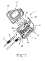
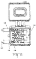
- FIG. 1 A first embodiment of an apparatus 1 according to the invention is shown in Figures 1, 2 and 3.
- the drawings show various perspective views of the apparatus 1 according to the invention for making contact with foil conductors, in particular of a solar module.
- the apparatus 1 consists of a housing 2 with a housing base 3 and lateral walls 4.
- the housing 2 has two connecting regions, a first connecting region 5, which is provided in the housing base 3 for making contact with the solar module and a second connecting region 6 which is provided in one of the lateral walls 4 of the housing and is designed for connecting with at least one plug connector 7.
- two plug connectors 7 and 7' can be connected at the second connecting region 6.
- the two female connectors 7 and 7' have coding ribs 8 for distinguishing the plug connectors for plus potential and minus potential.
- the actual female contact is located inside the female connector 7, 7' in a safe-to-touch manner. By virtue of the coded socket housing it is not possible to mis-mate the female connectors 7, 7'. In the plugged state, the plugged connection between the second connecting region and the female connectors 7, 7' is sealed against water spray.
- the first connecting region 5 is arranged on the housing base 3. It has a centring ring 9 which is used for centring the connecting region 5 and therefore the housing 2 in an opening (see Figure 6, reference 42) in a glass sheet of a solar module.
- the first connecting region 5 has an opening 10 in the housing base 3 within the centring ring 9. The foil conductors are inserted into the housing 2 through this opening 10.
- a diaphragm cover 11 is provided on the housing 2.
- This diaphragm cover 11 has a peripheral sealing ring 12.
- the sealing ring 12 engages in a corresponding sealing groove 13 of the housing 2 when the diaphragm cover 11 is closed.
- the diaphragm cover 11 has, in the central region, a diaphragm 14 which, due to an undulating design of the material in the region 15 surrounding the diaphragm is easily moveable relative to the cover 11. If the diaphragm cover 11 is closed, it closes off the housing 2 in a sealing manner with the sealing lip 12. Due to temperature variations or corresponding changes in the ambient pressure, pressure in the interior of the housing can then be compensated with the aid of the diaphragm 14.
- the membrane cover has a hinge 16 in the form of three hinge straps.
- the diaphragm cover 11 is supported on the housing 2 by means of the hinge 16. As the diaphragm cover 11 is often produced from a different material as the housing 2, it can be connected to the housing 2 in a latching manner in the region of the hinges.
- the diaphragm cover 11 also has an opening aid 17 into which a tool can be inserted into an undercut 18 so that with the help of the tool, the diaphragm cover 11 can be opened.
- Two conductor rails 21 and 22 are located in the housing 2 of the apparatus according to the invention and according to the first embodiment.
- the conductor rails 21 and 22 each have a contact region 23 for detachable connection to a foil conductor.
- the contact regions 23 consist of metallic clamping springs that allow clamping of the foil conductors between the clamping springs and conductor rails 21, 22. Reliable contacting of the foil conductors is thus ensured by the use of purely metallic contact elements. In addition, contacting is achieved by energy stores in the clamping springs.
- the conductor rails 21, 22 also have, in each case, a terminal area 25 for receiving electronic modules or lead portions.
- the two terminal areas 25 are arranged opposite to one another so they can receive, for example, the lead portions of a diode.
- Each conductor rail 21, 22 is also connected to a contact 26 of the second connecting region 6.
- the contacts 26 are surrounded by an inner seal 27 which ensures the sealing of the contact to the housing.
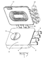
- an intermediate cover 30 is provided between the housing 2 and the diaphragm cover 11.
- This intermediate cover 30 has a plurality of recesses 31 which serve to expose the terminal areas 25 through the intermediate cover 30. It is thus possible that even when the intermediate cover 30 is closed, an electronic component, for example a diode 32, can be inserted and is accessible.
- the intermediate cover 30 also has a sealing funnel 33.
- this sealing funnel 33 By means of this sealing funnel 33, the space between the intermediate cover 30 and the housing 2 can be filled with a sealing compound.
- the intermediate cover 30 has a latching lever 34 for latching on the housing 2.
- the latching lever 34 is also sealed and the intermediate cover 30 can no longer be opened without destroying the apparatus.
- FIGS. 4 and 5 now show a second embodiment of the apparatus according to the invention.
- This embodiment essentially differs from the first embodiment in that not only two foil conductors but four foil conductors can be connected. In this apparatus, moreover, there is no intermediate cover.
- Each conductor rail has one or more terminal areas 25' for receiving and making contact with conductor ends, for example a diode 32 or a conductor portion 35.
- the conductor rails 21' and 22' also have a contact region 23 with a metallic clamping spring.
- the diaphragm cover 11 is also substantially designed to correspond to the diaphragm cover of the first embodiment. It has a peripheral sealing lip 12, a hinge 16 and an opening aid 17.
- the diaphragm cover 11 also has covering caps 37 for covering the second connecting region 6, or the plug connector receivers of the second connecting region.
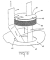
- the solar module 40 has two foil conductors 41 which are to be guided through an opening 42 in the upper glass plate 43 of the solar module out of the solar module and into the apparatus.
- a gel seal 44 is provided which is adapted in shape to the opening 42.
- the gel seal 44 consists of a carrier element 45 and the gel element 46 carried by the carrier element 45.
- the carrier element 45 has two slots 47 for receiving the foil conductors 41.
- the solar module can be optimally sealed by means of the gel seal 44.
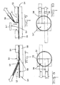
- the second gel seal consists of two semicircular elements 51, 51', which are inserted into a semicircular opening 52 in a glass plate 53 of a solar panel 54.
- Two foil conductors 56 are located between the two glass plates 53 and 55 of the solar panel. These foil conductors 56 are initially bent in a first direction to insert the first partial seal 51. The two foil conductors 56 are then bent over the partial seal 51 to insert the second partial seal 51'. An optimal seal is also achieved with this type of gel seal from two partial seals 51, 52.
- Figure 11 shows a cross-section though a solar module 54 with a first glass plate 55 and a second glass plate 53.
- Two foil conductors 56 pass through the opening 52 in the second glass plate 53.
- the opening 52 is sealed by means of two partial seals 51 and 51'.
- An apparatus according to the invention is applied to the solar module 54. Only a part of the housing 2 can be seen.
- a cross-section through the first connecting region 5 with the centring ring 9 is shown.
- spring elements 57 are provided in the first connecting region 5 which are connected to the first connecting region and spring-load perpendicularly to the extension of the glass plates. Pressure is thus exerted on the gel seal and the sealing effect is ensured.
- Figure 12 shows a perspective view of an apparatus with an opened diaphragm cover which differs from Figure 4 in that two screw terminal areas 126 are provided for making contact with a cable 107 in each case.
- screw terminal areas the use of spring-loaded terminals is also possible.
- Figure 13 shows an apparatus according to the invention with six conductor rails 222.
- the conductors rails 222 have two terminal areas 225 in each case and can be connected to one another thereby as desired.
Landscapes
- Photovoltaic Devices (AREA)
Priority Applications (1)
| Application Number | Priority Date | Filing Date | Title |
|---|---|---|---|
| EP00310224A EP1102354B1 (fr) | 1999-11-17 | 2000-11-17 | Dispositif pour contacter des conducteurs à feuille, en particulier d'un module solaire |
Applications Claiming Priority (3)
| Application Number | Priority Date | Filing Date | Title |
|---|---|---|---|
| EP99122852 | 1999-11-17 | ||
| EP99122852 | 1999-11-17 | ||
| EP00310224A EP1102354B1 (fr) | 1999-11-17 | 2000-11-17 | Dispositif pour contacter des conducteurs à feuille, en particulier d'un module solaire |
Publications (3)
| Publication Number | Publication Date |
|---|---|
| EP1102354A2 true EP1102354A2 (fr) | 2001-05-23 |
| EP1102354A3 EP1102354A3 (fr) | 2002-07-24 |
| EP1102354B1 EP1102354B1 (fr) | 2008-05-28 |
Family
ID=26073365
Family Applications (1)
| Application Number | Title | Priority Date | Filing Date |
|---|---|---|---|
| EP00310224A Expired - Lifetime EP1102354B1 (fr) | 1999-11-17 | 2000-11-17 | Dispositif pour contacter des conducteurs à feuille, en particulier d'un module solaire |
Country Status (1)
| Country | Link |
|---|---|
| EP (1) | EP1102354B1 (fr) |
Cited By (18)
| Publication number | Priority date | Publication date | Assignee | Title |
|---|---|---|---|---|
| JP2003229592A (ja) * | 2002-01-31 | 2003-08-15 | Kitani Denki Kk | 太陽電池モジュール用端子ボックス |
| DE20311184U1 (de) * | 2003-07-21 | 2004-02-19 | Tyco Electronics Amp Gmbh | Anschlussdose zum Anschließen an ein Solarpaneel |
| DE20311183U1 (de) * | 2003-07-21 | 2004-07-08 | Tyco Electronics Amp Gmbh | Anschlussdose für ein Solarpaneel und Solarpaneel |
| DE102004020958B3 (de) * | 2004-04-28 | 2005-08-25 | Rose Systemtechnik Gmbh | Anschlußklemme und damit gebildete Anschlußbox |
| DE102004025627A1 (de) * | 2004-05-25 | 2005-12-22 | Tyco Electronics Amp Gmbh | Solarmodul mit Anschlusselement |
| DE102005025976A1 (de) * | 2005-06-03 | 2006-12-14 | Günther Spelsberg GmbH & Co. KG | Elektrische Anschluß- und Verbindungsdose für ein Solarzellenmodul |
| EP1777754A1 (fr) * | 2005-10-20 | 2007-04-25 | Tyco Electronics AMP GmbH | Dispositif de connexion ayant une diode pour connecter un conducteur électrique à une ligne de raccordement |
| WO2008095669A1 (fr) * | 2007-02-05 | 2008-08-14 | Phoenix Contact Gmbh & Co. Kg | Boîtier de raccordement et de connexion pour un module solaire |
| WO2008095668A1 (fr) * | 2007-02-05 | 2008-08-14 | Phoenix Contact Gmbh & Co. Kg | Boîtier de raccordement et de connexion pour un module solaire |
| DE102008022298B3 (de) * | 2008-03-13 | 2009-04-16 | Fpe Fischer Gmbh | Verbindungsbox für Solar-Module |
| WO2009074622A1 (fr) * | 2007-12-11 | 2009-06-18 | Lasen Development Llc | Dispositif de connexion électrique, en particulier pour panneaux solaires à cellules photovoltaïques |
| DE102008022055A1 (de) * | 2008-05-03 | 2009-11-05 | Lumberg Connect Gmbh | Anschlussdose für ein Solarmodul |
| US8033859B2 (en) | 2007-02-05 | 2011-10-11 | Phoenix Contact Gmbh & Co. Kg | Connection and junction box for a solar module |
| WO2011144546A1 (fr) | 2010-05-21 | 2011-11-24 | Commissariat A L'energie Atomique Et Aux Energies Alternatives | Dispositif de connexion électrique destiné à raccorder électriquement un panneau photovoltaïque |
| DE102010023292A1 (de) | 2010-06-10 | 2011-12-15 | Wago Verwaltungsgesellschaft Mbh | Anschlussstecker |
| EP2482406A3 (fr) * | 2011-01-29 | 2013-12-18 | Kostal Industrie Elektrik GmbH | Boîtier de raccordement et de connexion électrique pour un module de cellules solaires ainsi que procédé de fabrication d'une connexion électrique |
| KR101452448B1 (ko) | 2013-07-16 | 2014-10-24 | 주식회사 에이 씨 에스 | 임의 개조 방지구조를 갖는 태양광 발전시스템용 정션박스 |
| WO2024013151A1 (fr) * | 2022-07-12 | 2024-01-18 | Weidmüller Interface GmbH & Co. KG | Module photovoltaïque et unité de connexion pour un module photovoltaïque |
Citations (7)
| Publication number | Priority date | Publication date | Assignee | Title |
|---|---|---|---|---|
| DE2256657A1 (de) * | 1972-11-18 | 1974-05-22 | Bbc Brown Boveri & Cie | Anschluss- oder lichtauslassdose insbesondere zum verbinden von deckenleuchten |
| US4460232A (en) * | 1982-05-24 | 1984-07-17 | Amp, Incorporated | Junction box for solar modules |
| GB2260864A (en) * | 1991-10-24 | 1993-04-28 | Bill Moule & Sons Ltd | Terminal box with lid |
| DE29706750U1 (de) * | 1997-04-15 | 1997-05-28 | Albert Ackermann GmbH & Co. KG, 51643 Gummersbach | Anschlußvorrichtung für elektrische Flachkabel |
| WO1998025325A1 (fr) * | 1996-11-30 | 1998-06-11 | Atlantis Solar Systeme Ag | Dispositif de serrage pour le raccordement de connexions electriques d'elements solaires |
| DE29906707U1 (de) * | 1999-04-15 | 1999-07-22 | Siemens AG, 80333 München | Modul zum Anschluß von Aktoren und/oder Sensoren |
| US5947760A (en) * | 1995-12-12 | 1999-09-07 | Baumer Electric Ag | Contacting arrangement for multicore flat cables |
-
2000
- 2000-11-17 EP EP00310224A patent/EP1102354B1/fr not_active Expired - Lifetime
Patent Citations (7)
| Publication number | Priority date | Publication date | Assignee | Title |
|---|---|---|---|---|
| DE2256657A1 (de) * | 1972-11-18 | 1974-05-22 | Bbc Brown Boveri & Cie | Anschluss- oder lichtauslassdose insbesondere zum verbinden von deckenleuchten |
| US4460232A (en) * | 1982-05-24 | 1984-07-17 | Amp, Incorporated | Junction box for solar modules |
| GB2260864A (en) * | 1991-10-24 | 1993-04-28 | Bill Moule & Sons Ltd | Terminal box with lid |
| US5947760A (en) * | 1995-12-12 | 1999-09-07 | Baumer Electric Ag | Contacting arrangement for multicore flat cables |
| WO1998025325A1 (fr) * | 1996-11-30 | 1998-06-11 | Atlantis Solar Systeme Ag | Dispositif de serrage pour le raccordement de connexions electriques d'elements solaires |
| DE29706750U1 (de) * | 1997-04-15 | 1997-05-28 | Albert Ackermann GmbH & Co. KG, 51643 Gummersbach | Anschlußvorrichtung für elektrische Flachkabel |
| DE29906707U1 (de) * | 1999-04-15 | 1999-07-22 | Siemens AG, 80333 München | Modul zum Anschluß von Aktoren und/oder Sensoren |
Cited By (35)
| Publication number | Priority date | Publication date | Assignee | Title |
|---|---|---|---|---|
| JP2003229592A (ja) * | 2002-01-31 | 2003-08-15 | Kitani Denki Kk | 太陽電池モジュール用端子ボックス |
| US7134883B2 (en) | 2003-07-21 | 2006-11-14 | Tyco Electronics Amp Gmbh | Connecting box for connecting to a solar panel |
| DE20311184U1 (de) * | 2003-07-21 | 2004-02-19 | Tyco Electronics Amp Gmbh | Anschlussdose zum Anschließen an ein Solarpaneel |
| EP1501157A2 (fr) * | 2003-07-21 | 2005-01-26 | Tyco Electronics AMP GmbH | Boíte de connexion pour un panneau solaire et le panneau solaire |
| EP1501133A1 (fr) * | 2003-07-21 | 2005-01-26 | Tyco Electronics AMP GmbH | Boite de raccordement pour le raccordement à un panneau solaire |
| DE20311183U1 (de) * | 2003-07-21 | 2004-07-08 | Tyco Electronics Amp Gmbh | Anschlussdose für ein Solarpaneel und Solarpaneel |
| US7097516B2 (en) | 2003-07-21 | 2006-08-29 | Tyco Electronics Amp Gmbh | Connecting box for a solar panel and solar panel |
| EP1501157A3 (fr) * | 2003-07-21 | 2007-03-14 | Tyco Electronics AMP GmbH | Boîte de connexion pour un panneau solaire et le panneau solaire |
| DE102004020958B3 (de) * | 2004-04-28 | 2005-08-25 | Rose Systemtechnik Gmbh | Anschlußklemme und damit gebildete Anschlußbox |
| DE102004025627A1 (de) * | 2004-05-25 | 2005-12-22 | Tyco Electronics Amp Gmbh | Solarmodul mit Anschlusselement |
| US7705234B2 (en) | 2004-05-25 | 2010-04-27 | Tyco Electronics Amp Gmbh | Solar module having a connecting element |
| DE102005025976A1 (de) * | 2005-06-03 | 2006-12-14 | Günther Spelsberg GmbH & Co. KG | Elektrische Anschluß- und Verbindungsdose für ein Solarzellenmodul |
| DE102005025976B4 (de) * | 2005-06-03 | 2007-03-15 | Günther Spelsberg GmbH & Co. KG | Elektrische Anschluß- und Verbindungsdose für ein Solarzellenmodul |
| EP1777754A1 (fr) * | 2005-10-20 | 2007-04-25 | Tyco Electronics AMP GmbH | Dispositif de connexion ayant une diode pour connecter un conducteur électrique à une ligne de raccordement |
| EP2146381A3 (fr) * | 2005-10-20 | 2010-11-24 | Tyco Electronics AMP GmbH | Dispositif de connexion doté d'une diode pour la connexion d'un conducteur électrique à un fil de connexion |
| EP2146381A2 (fr) * | 2005-10-20 | 2010-01-20 | Tyco Electronics AMP GmbH | Dispositif de connexion doté d'une diode pour la connexion d'un conducteur électrique à un fil de connexion |
| US7931488B2 (en) | 2007-02-05 | 2011-04-26 | Phoenix Contact Gmbh & Co. Kg | Connection and junction box for a solar module |
| CN101606295B (zh) * | 2007-02-05 | 2012-05-02 | 菲尼克斯电气公司 | 用于太阳能模块的端子接线箱 |
| US8366471B2 (en) | 2007-02-05 | 2013-02-05 | Phoenix Contact Gmbh & Co. Kg | Connection and junction box for a solar module |
| CN101606294B (zh) * | 2007-02-05 | 2013-01-02 | 菲尼克斯电气公司 | 用于太阳能模块的端子接线箱 |
| US8033859B2 (en) | 2007-02-05 | 2011-10-11 | Phoenix Contact Gmbh & Co. Kg | Connection and junction box for a solar module |
| WO2008095669A1 (fr) * | 2007-02-05 | 2008-08-14 | Phoenix Contact Gmbh & Co. Kg | Boîtier de raccordement et de connexion pour un module solaire |
| WO2008095670A1 (fr) | 2007-02-05 | 2008-08-14 | Phoenix Contact Gmbh & Co. Kg | Boîtier de raccordement et de connexion pour un module solaire |
| WO2008095668A1 (fr) * | 2007-02-05 | 2008-08-14 | Phoenix Contact Gmbh & Co. Kg | Boîtier de raccordement et de connexion pour un module solaire |
| WO2009074622A1 (fr) * | 2007-12-11 | 2009-06-18 | Lasen Development Llc | Dispositif de connexion électrique, en particulier pour panneaux solaires à cellules photovoltaïques |
| US7641522B2 (en) | 2007-12-11 | 2010-01-05 | Lasen Development Llc | Electrical-connection device, particularly for photovoltaic-cell solar panels |
| DE102008022298B3 (de) * | 2008-03-13 | 2009-04-16 | Fpe Fischer Gmbh | Verbindungsbox für Solar-Module |
| DE102008022055B4 (de) * | 2008-05-03 | 2010-01-21 | Lumberg Connect Gmbh | Anschlussdose für ein Solarmodul |
| DE102008022055A1 (de) * | 2008-05-03 | 2009-11-05 | Lumberg Connect Gmbh | Anschlussdose für ein Solarmodul |
| WO2011144546A1 (fr) | 2010-05-21 | 2011-11-24 | Commissariat A L'energie Atomique Et Aux Energies Alternatives | Dispositif de connexion électrique destiné à raccorder électriquement un panneau photovoltaïque |
| DE102010023292A1 (de) | 2010-06-10 | 2011-12-15 | Wago Verwaltungsgesellschaft Mbh | Anschlussstecker |
| DE102010023292B4 (de) * | 2010-06-10 | 2012-04-26 | Wago Verwaltungsgesellschaft Mbh | Anschlussstecker |
| EP2482406A3 (fr) * | 2011-01-29 | 2013-12-18 | Kostal Industrie Elektrik GmbH | Boîtier de raccordement et de connexion électrique pour un module de cellules solaires ainsi que procédé de fabrication d'une connexion électrique |
| KR101452448B1 (ko) | 2013-07-16 | 2014-10-24 | 주식회사 에이 씨 에스 | 임의 개조 방지구조를 갖는 태양광 발전시스템용 정션박스 |
| WO2024013151A1 (fr) * | 2022-07-12 | 2024-01-18 | Weidmüller Interface GmbH & Co. KG | Module photovoltaïque et unité de connexion pour un module photovoltaïque |
Also Published As
| Publication number | Publication date |
|---|---|
| EP1102354B1 (fr) | 2008-05-28 |
| EP1102354A3 (fr) | 2002-07-24 |
Similar Documents
| Publication | Publication Date | Title |
|---|---|---|
| US6582249B1 (en) | Apparatus for contacting foil conductors, in particular of a solar module | |
| EP1102354A2 (fr) | Dispositif pour contacter des conducteurs à feuille, en particulier d'un module solaire | |
| EP1501157B2 (fr) | Boîte de connexion pour un panneau solaire et le panneau solaire | |
| EP1729369B1 (fr) | Dispositif pour la mise en contact avec des conducteurs à feuille | |
| US8500462B2 (en) | Junction box for a photovoltaic solar panel | |
| US7972177B2 (en) | Slide clip | |
| JP2009130373A (ja) | 太陽電池パネル用接続箱 | |
| EP1926181A2 (fr) | Connecteur résistant à l'eau et connecteur de connexion | |
| CN109844987B (zh) | 电池固定器 | |
| US20110183531A1 (en) | Junction box for photovoltaic modules | |
| US6638090B2 (en) | Waterproof connector used for a flexible flat cable | |
| JP2004342408A (ja) | シート状導電路用コネクタ | |
| US7056137B1 (en) | Electrical connectors having a sealing element | |
| US7338319B2 (en) | Sealing system for multiterminal electrical connector | |
| KR100235267B1 (ko) | 중공부재의 밀봉 조립체 및 중공부재의 밀봉 방법 | |
| JPH08185920A (ja) | 回路基板の電気的接続構造 | |
| US5772467A (en) | Terminal free connector and method | |
| US6293815B1 (en) | Connector having self-sealing membrane | |
| JP4153366B2 (ja) | 圧接コネクタ | |
| KR101850218B1 (ko) | 실링제 및 이를 구비한 방수 커넥터 | |
| CN209692059U (zh) | 防水连接器 | |
| JP2004356013A (ja) | 圧接端子及びシール材の固定構造 | |
| JPH028369Y2 (fr) | ||
| US20240339779A1 (en) | Plug-in connector having a frame | |
| JPH11121083A (ja) | 防水コネクタ |
Legal Events
| Date | Code | Title | Description |
|---|---|---|---|
| PUAI | Public reference made under article 153(3) epc to a published international application that has entered the european phase |
Free format text: ORIGINAL CODE: 0009012 |
|
| AK | Designated contracting states |
Kind code of ref document: A2 Designated state(s): AT BE CH CY DE DK ES FI FR GB GR IE IT LI LU MC NL PT SE TR |
|
| AX | Request for extension of the european patent |
Free format text: AL;LT;LV;MK;RO;SI |
|
| PUAL | Search report despatched |
Free format text: ORIGINAL CODE: 0009013 |
|
| AK | Designated contracting states |
Kind code of ref document: A3 Designated state(s): AT BE CH CY DE DK ES FI FR GB GR IE IT LI LU MC NL PT SE TR |
|
| AX | Request for extension of the european patent |
Free format text: AL;LT;LV;MK;RO;SI |
|
| RIC1 | Information provided on ipc code assigned before grant |
Free format text: 7H 01R 12/08 A, 7H 01R 13/52 B |
|
| 17P | Request for examination filed |
Effective date: 20020809 |
|
| AKX | Designation fees paid |
Designated state(s): AT BE CH CY DE DK ES FI FR GB GR IE IT LI LU MC NL PT SE TR |
|
| 17Q | First examination report despatched |
Effective date: 20061013 |
|
| GRAP | Despatch of communication of intention to grant a patent |
Free format text: ORIGINAL CODE: EPIDOSNIGR1 |
|
| GRAS | Grant fee paid |
Free format text: ORIGINAL CODE: EPIDOSNIGR3 |
|
| GRAA | (expected) grant |
Free format text: ORIGINAL CODE: 0009210 |
|
| AK | Designated contracting states |
Kind code of ref document: B1 Designated state(s): AT BE CH CY DE DK ES FI FR GB GR IE IT LI LU MC NL PT SE TR |
|
| REG | Reference to a national code |
Ref country code: GB Ref legal event code: FG4D |
|
| REG | Reference to a national code |
Ref country code: CH Ref legal event code: EP |
|
| REF | Corresponds to: |
Ref document number: 60039019 Country of ref document: DE Date of ref document: 20080710 Kind code of ref document: P |
|
| REG | Reference to a national code |
Ref country code: IE Ref legal event code: FG4D |
|
| PG25 | Lapsed in a contracting state [announced via postgrant information from national office to epo] |
Ref country code: FI Free format text: LAPSE BECAUSE OF FAILURE TO SUBMIT A TRANSLATION OF THE DESCRIPTION OR TO PAY THE FEE WITHIN THE PRESCRIBED TIME-LIMIT Effective date: 20080528 |
|
| REG | Reference to a national code |
Ref country code: ES Ref legal event code: FG2A Ref document number: 2306650 Country of ref document: ES Kind code of ref document: T3 |
|
| PG25 | Lapsed in a contracting state [announced via postgrant information from national office to epo] |
Ref country code: NL Free format text: LAPSE BECAUSE OF FAILURE TO SUBMIT A TRANSLATION OF THE DESCRIPTION OR TO PAY THE FEE WITHIN THE PRESCRIBED TIME-LIMIT Effective date: 20080528 Ref country code: AT Free format text: LAPSE BECAUSE OF FAILURE TO SUBMIT A TRANSLATION OF THE DESCRIPTION OR TO PAY THE FEE WITHIN THE PRESCRIBED TIME-LIMIT Effective date: 20080528 |
|
| NLV1 | Nl: lapsed or annulled due to failure to fulfill the requirements of art. 29p and 29m of the patents act | ||
| PG25 | Lapsed in a contracting state [announced via postgrant information from national office to epo] |
Ref country code: DK Free format text: LAPSE BECAUSE OF FAILURE TO SUBMIT A TRANSLATION OF THE DESCRIPTION OR TO PAY THE FEE WITHIN THE PRESCRIBED TIME-LIMIT Effective date: 20080528 Ref country code: PT Free format text: LAPSE BECAUSE OF FAILURE TO SUBMIT A TRANSLATION OF THE DESCRIPTION OR TO PAY THE FEE WITHIN THE PRESCRIBED TIME-LIMIT Effective date: 20081028 Ref country code: SE Free format text: LAPSE BECAUSE OF FAILURE TO SUBMIT A TRANSLATION OF THE DESCRIPTION OR TO PAY THE FEE WITHIN THE PRESCRIBED TIME-LIMIT Effective date: 20080828 |
|
| PG25 | Lapsed in a contracting state [announced via postgrant information from national office to epo] |
Ref country code: BE Free format text: LAPSE BECAUSE OF FAILURE TO SUBMIT A TRANSLATION OF THE DESCRIPTION OR TO PAY THE FEE WITHIN THE PRESCRIBED TIME-LIMIT Effective date: 20080528 |
|
| PLBE | No opposition filed within time limit |
Free format text: ORIGINAL CODE: 0009261 |
|
| STAA | Information on the status of an ep patent application or granted ep patent |
Free format text: STATUS: NO OPPOSITION FILED WITHIN TIME LIMIT |
|
| 26N | No opposition filed |
Effective date: 20090303 |
|
| PG25 | Lapsed in a contracting state [announced via postgrant information from national office to epo] |
Ref country code: MC Free format text: LAPSE BECAUSE OF NON-PAYMENT OF DUE FEES Effective date: 20081130 |
|
| REG | Reference to a national code |
Ref country code: CH Ref legal event code: PL |
|
| REG | Reference to a national code |
Ref country code: IE Ref legal event code: MM4A |
|
| PG25 | Lapsed in a contracting state [announced via postgrant information from national office to epo] |
Ref country code: LI Free format text: LAPSE BECAUSE OF NON-PAYMENT OF DUE FEES Effective date: 20081130 Ref country code: IE Free format text: LAPSE BECAUSE OF NON-PAYMENT OF DUE FEES Effective date: 20081117 Ref country code: CH Free format text: LAPSE BECAUSE OF NON-PAYMENT OF DUE FEES Effective date: 20081130 |
|
| PG25 | Lapsed in a contracting state [announced via postgrant information from national office to epo] |
Ref country code: LU Free format text: LAPSE BECAUSE OF NON-PAYMENT OF DUE FEES Effective date: 20081117 |
|
| PG25 | Lapsed in a contracting state [announced via postgrant information from national office to epo] |
Ref country code: CY Free format text: LAPSE BECAUSE OF FAILURE TO SUBMIT A TRANSLATION OF THE DESCRIPTION OR TO PAY THE FEE WITHIN THE PRESCRIBED TIME-LIMIT Effective date: 20080528 |
|
| PG25 | Lapsed in a contracting state [announced via postgrant information from national office to epo] |
Ref country code: GR Free format text: LAPSE BECAUSE OF FAILURE TO SUBMIT A TRANSLATION OF THE DESCRIPTION OR TO PAY THE FEE WITHIN THE PRESCRIBED TIME-LIMIT Effective date: 20080829 |
|
| REG | Reference to a national code |
Ref country code: FR Ref legal event code: PLFP Year of fee payment: 16 |
|
| REG | Reference to a national code |
Ref country code: FR Ref legal event code: CD Owner name: TE CONNECTIVITY GERMANY GMBH Effective date: 20151027 |
|
| REG | Reference to a national code |
Ref country code: FR Ref legal event code: PLFP Year of fee payment: 17 |
|
| REG | Reference to a national code |
Ref country code: FR Ref legal event code: PLFP Year of fee payment: 18 |
|
| REG | Reference to a national code |
Ref country code: FR Ref legal event code: PLFP Year of fee payment: 19 |
|
| PGFP | Annual fee paid to national office [announced via postgrant information from national office to epo] |
Ref country code: DE Payment date: 20181106 Year of fee payment: 19 |
|
| PGFP | Annual fee paid to national office [announced via postgrant information from national office to epo] |
Ref country code: ES Payment date: 20181203 Year of fee payment: 19 Ref country code: GB Payment date: 20181114 Year of fee payment: 19 Ref country code: FR Payment date: 20181011 Year of fee payment: 19 Ref country code: TR Payment date: 20181101 Year of fee payment: 19 Ref country code: IT Payment date: 20181122 Year of fee payment: 19 |
|
| REG | Reference to a national code |
Ref country code: DE Ref legal event code: R119 Ref document number: 60039019 Country of ref document: DE |
|
| GBPC | Gb: european patent ceased through non-payment of renewal fee |
Effective date: 20191117 |
|
| PG25 | Lapsed in a contracting state [announced via postgrant information from national office to epo] |
Ref country code: FR Free format text: LAPSE BECAUSE OF NON-PAYMENT OF DUE FEES Effective date: 20191130 Ref country code: GB Free format text: LAPSE BECAUSE OF NON-PAYMENT OF DUE FEES Effective date: 20191117 Ref country code: IT Free format text: LAPSE BECAUSE OF NON-PAYMENT OF DUE FEES Effective date: 20191117 Ref country code: DE Free format text: LAPSE BECAUSE OF NON-PAYMENT OF DUE FEES Effective date: 20200603 |
|
| REG | Reference to a national code |
Ref country code: ES Ref legal event code: FD2A Effective date: 20210526 |
|
| PG25 | Lapsed in a contracting state [announced via postgrant information from national office to epo] |
Ref country code: ES Free format text: LAPSE BECAUSE OF NON-PAYMENT OF DUE FEES Effective date: 20191118 |
|
| PG25 | Lapsed in a contracting state [announced via postgrant information from national office to epo] |
Ref country code: TR Free format text: LAPSE BECAUSE OF NON-PAYMENT OF DUE FEES Effective date: 20191117 |