EP1102131A2 - Space securing member, developing device, charging device and process cartridge - Google Patents
Space securing member, developing device, charging device and process cartridge Download PDFInfo
- Publication number
- EP1102131A2 EP1102131A2 EP00125002A EP00125002A EP1102131A2 EP 1102131 A2 EP1102131 A2 EP 1102131A2 EP 00125002 A EP00125002 A EP 00125002A EP 00125002 A EP00125002 A EP 00125002A EP 1102131 A2 EP1102131 A2 EP 1102131A2
- Authority
- EP
- European Patent Office
- Prior art keywords
- photosensitive drum
- securing member
- electrophotographic photosensitive
- space
- space securing
- Prior art date
- Legal status (The legal status is an assumption and is not a legal conclusion. Google has not performed a legal analysis and makes no representation as to the accuracy of the status listed.)
- Granted
Links
Images


Classifications
-
- G—PHYSICS
- G03—PHOTOGRAPHY; CINEMATOGRAPHY; ANALOGOUS TECHNIQUES USING WAVES OTHER THAN OPTICAL WAVES; ELECTROGRAPHY; HOLOGRAPHY
- G03G—ELECTROGRAPHY; ELECTROPHOTOGRAPHY; MAGNETOGRAPHY
- G03G21/00—Arrangements not provided for by groups G03G13/00 - G03G19/00, e.g. cleaning, elimination of residual charge
- G03G21/16—Mechanical means for facilitating the maintenance of the apparatus, e.g. modular arrangements
- G03G21/18—Mechanical means for facilitating the maintenance of the apparatus, e.g. modular arrangements using a processing cartridge, whereby the process cartridge comprises at least two image processing means in a single unit
- G03G21/1803—Arrangements or disposition of the complete process cartridge or parts thereof
- G03G21/1817—Arrangements or disposition of the complete process cartridge or parts thereof having a submodular arrangement
- G03G21/1821—Arrangements or disposition of the complete process cartridge or parts thereof having a submodular arrangement means for connecting the different parts of the process cartridge, e.g. attachment, positioning of parts with each other, pressure/distance regulation
-
- G—PHYSICS
- G03—PHOTOGRAPHY; CINEMATOGRAPHY; ANALOGOUS TECHNIQUES USING WAVES OTHER THAN OPTICAL WAVES; ELECTROGRAPHY; HOLOGRAPHY
- G03G—ELECTROGRAPHY; ELECTROPHOTOGRAPHY; MAGNETOGRAPHY
- G03G15/00—Apparatus for electrographic processes using a charge pattern
- G03G15/02—Apparatus for electrographic processes using a charge pattern for laying down a uniform charge, e.g. for sensitising; Corona discharge devices
- G03G15/0208—Apparatus for electrographic processes using a charge pattern for laying down a uniform charge, e.g. for sensitising; Corona discharge devices by contact, friction or induction, e.g. liquid charging apparatus
-
- G—PHYSICS
- G03—PHOTOGRAPHY; CINEMATOGRAPHY; ANALOGOUS TECHNIQUES USING WAVES OTHER THAN OPTICAL WAVES; ELECTROGRAPHY; HOLOGRAPHY
- G03G—ELECTROGRAPHY; ELECTROPHOTOGRAPHY; MAGNETOGRAPHY
- G03G15/00—Apparatus for electrographic processes using a charge pattern
- G03G15/06—Apparatus for electrographic processes using a charge pattern for developing
- G03G15/08—Apparatus for electrographic processes using a charge pattern for developing using a solid developer, e.g. powder developer
- G03G15/0806—Apparatus for electrographic processes using a charge pattern for developing using a solid developer, e.g. powder developer on a donor element, e.g. belt, roller
- G03G15/0813—Apparatus for electrographic processes using a charge pattern for developing using a solid developer, e.g. powder developer on a donor element, e.g. belt, roller characterised by means in the developing zone having an interaction with the image carrying member, e.g. distance holders
-
- G—PHYSICS
- G03—PHOTOGRAPHY; CINEMATOGRAPHY; ANALOGOUS TECHNIQUES USING WAVES OTHER THAN OPTICAL WAVES; ELECTROGRAPHY; HOLOGRAPHY
- G03G—ELECTROGRAPHY; ELECTROPHOTOGRAPHY; MAGNETOGRAPHY
- G03G2215/00—Apparatus for electrophotographic processes
- G03G2215/01—Apparatus for electrophotographic processes for producing multicoloured copies
- G03G2215/0103—Plural electrographic recording members
- G03G2215/0119—Linear arrangement adjacent plural transfer points
Definitions
- the present invention relates to a process cartridge detachably mountable to a main body of an electrophotographic image forming apparatus, a space securing member between a photosensitive drum and a developing roller, a charging roller or the like, a developing device and a charging device.
- the electrophotographic image forming apparatus is to form an image on a recording medium with using an electrophotographic image forming process.
- the electrophotographic image forming apparatus may be exemplified by, for example, an electrophotographic copying machine, an electrophotographic printer (for example, a laser beam printer, an LED printer or the like), a facsimile machine, a word processor and so on.
- the process cartridge makes charging means, developing means or cleaning means and an electrophotographic photosensitive drum integrally into a cartridge which is detachably mountable to the main body of the electrophotographic image forming apparatus.
- the process cartridge also makes at least one of the charging means, the developing means and the cleaning means and an electrophotographic photosensitive drum integrally into a cartridge which is detachably mountable to the main body of the electrophotographic image forming apparatus.
- the process cartridge further makes at least the developing means and the electrophotographic photosensitive drum integrally into a cartridge which is detachably mountable to the main body of the electrophotographic image forming apparatus.
- An image forming apparatus such as a printer using an electrophotographic process conducts image recording in such a manner that a photosensitive drum which constitutes an image bearing member is uniformly charged, the photosensitive drum is selectively exposed to form a latent image, the latent image is visualized by toner which is a developer, the toner image is transferred onto a recording medium, and a heat or pressure is applied to the transferred toner image, to thereby fix the toner image onto the recording medium.
- the image forming apparatus thus structured may be accompanied by the supply of toner and the maintenance of various process means, and there have been practiced that the photosensitive drum, the charging means, the developing means, the cleaning means and so on are gathered within a frame and made into a cartridge as means for facilitating the supply of toner and the maintenance.
- a space between the photosensitive drum and a developing sleeve that supplies toner to the photosensitive drum must be maintained at a predetermined distance.
- a space securing member called "SD runner” is disposed on an end portion of the developing sleeve, and a gap (hereinafter referred to as an "SD gap") between the photosensitive drum and the developing sleeve is managed by the thickness of the SD runner.
- the photosensitive drum and the developing sleeve rotate mutually forward in such a manner that the peripheral surfaces of the photosensitive drum and the developing sleeve move in the same direction at the opposite portions of those members, and the SD runner holds the SD gap while rotating in that direction.
- the SD runner is urged by an urging force (hereinafter referred to as an "SD pressure") of a spring or the like so as not to separate an abutting portion of the SD runner from the photosensitive drum due to vibration or the like.
- SD pressure an urging force of a spring or the like
- the SD gap can be maintained without any problem.
- the rotating direction of the photosensitive drum is counter to the rotating direction of the developing sleeve, a peripheral speed difference between the photosensitive drum and the developing sleeve becomes larger than that in the case where the photosensitive drum and the developing sleeve rotate in the forward direction.
- the SD runner may be worn away.
- An object of the present invention is to provide a space securing member which is capable of maintaining a space between rotary members with high accuracy, a developing device using the space securing member, a charging device using the space securing member and a process cartridge using the space securing member.
- Another object of the present invention is to provide a space securing member which is capable of maintaining a space between an electrophotographic photosensitive drum and a developing roller with high accuracy, a developing device using the space securing member and a process cartridge using the developing device.
- Still another object of the present invention is to provide a space securing member which is capable of maintaining a space between an electrophotographic photosensitive drum and a charging roller with high accuracy, a charging device using the space securing member and a process cartridge using the charging device.
- Yet still another object of the present invention is to provide a space securing member having a circular hole rotatably supported by a rotary member and an arc configuration which is in area contact with an outer peripheral surface of another rotary member, a developing device using the space securing member, a charging device using the space securing member and a process cartridge using the space securing member.
- the term “longitudinal direction” is directed to a direction which crosses a conveying direction of a recording medium and is in parallel with a recording medium. Also, the term “right and left” is directed to the right and left when viewing the conveying direction of the recording medium from the upper side. Further, the term “upper” of the process cartridge is directed to the upper in a state where the process cartridge is mounted.
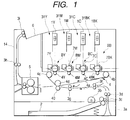
- Fig. 1 is a view showing an image forming apparatus to which the present invention is applied.
- the image forming apparatus is provided with: image forming stations 31Y, 31M, 31C and 31BK for forming toner images on photosensitive drums as image bearing members; an intermediate transfer belt 4a onto which the toner images are once transferred; a secondary transfer roller 40 which is transfer means that transfers the toner image formed on the intermediate transfer belt 4a onto the recording medium 2; sheet feeding means for feeding the recording medium 2 to a portion between the intermediate transfer belt 4a and the secondary transfer roller 40; sheet conveying means for conveying the recording medium 2 to the transfer means; fixing means; and sheet discharge means.
- a sheet feed cassette 3a that stacks and contains a plurality of recording mediums (for example, a recording sheet of paper, an OHP sheet, a cloth and so on) 2 therein is detachably mounted onto the image forming apparatus.
- the recording mediums 2 conveyed from the sheet feed cassette 3a by a pickup roller 3b are separated into each sheet by a pair of retard rollers 3c and then conveyed to a pair of registration rollers 3g by conveying rollers 3d and 3f.
- the pair of registration rollers 3g stop to rotate, and the recording medium 2 is abutted against a nip portion of the paired registration rollers 3g to correct the skew feed of the recording medium 2.
- photosensitive drums 7Y, 7M, 7C and 7BK for yellow, magenta, cyan and black are arranged tandem by process cartridges BY, BM, BC and BB as shown in Fig. 1.
- Optical scanning systems 1Y, 1M, 1C and 1BK are disposed for the respective process cartridges BY, BM, BC and BB, and after toner images are formed on the photosensitive drums for the respective colors in response to an image signal, the respective color toners are superimposed and transferred by the transfer rollers 4Y, 4M, 4C and 4BK onto the intermediate transfer belt 4a which runs in a direction indicated by an arrow in Fig. 1.
- the recording medium 2 is conveyed to the secondary transfer roller 40 at a predetermined timing, and the toner image on the intermediate transfer belt 4a is transferred onto the recording medium 2 and then fixed on the recording medium 2 by a fixing device 5. Thereafter, the recording medium 2 is discharged by a pair of discharge rollers 3h and 3i and then stacked on a tray 6 on a main body 14 of the apparatus.
- the image forming stations 31Y, 31M, 31C and 31BK constitute the process cartridges BY, BM, BC and BB, respectively, except for the optical scanning systems 1Y, 1M, 1C and 1BK.
- the structures of the process cartridges BY, BM, BC and BB are identical with each other, only the process cartridge BY will be described.
- the process cartridge BY is designed in such a manner that charging means, an exposing section, developing means and a transfer opening are disposed around the photosensitive drum 7.
- a two-component developer having magnetic carrier particles is employed. Therefore, the photosensitive drum 7 used in the embodiment of the present invention may be formed of an organic photoconductor usually employed, etc.
- a photosensitive drum having a surface layer made of a material having a resistance 10 2 to 10 14 ⁇ cm on an organic photoconductor, an amorphous silicon photoconductor or the like is used, charge-injection charging can be realized, to thereby prevent the occurrence of ozone and to effect a reduction in power consumption. Also, the charging property can be improved.
- a photosensitive drum 7 having a negatively chargeable organic photoconductor on a drum base made of aluminum is used.
- the charging means is a magnetic brush charger 8 using magnetic carriers.
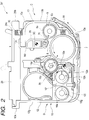
- the charger 8 has a stationary magnet 8b within a hollow cylindrical charging roller 8a which is rotatably supported. After transferring, the toner remaining on the photosensitive drum 7 is taken in the charger 8 that rotates in a direction indicated by an arrow in Fig. 2.
- the developing means is applied with a method of development in a state where the two-component developer is in contact (two-component contact development).
- FIG. 2 shows the developing means 10 for two-component magnetic brush development used in this embodiment.
- a developing roller (hereinafter referred to as a "developing sleeve”) 10d is shaped in a hollow cylinder and rotatably supported.
- a stationary magnet 10c is disposed within the developing sleeve 10d.
- the developing sleeve 10d rotates in the same direction as that of the photosensitive drum 7, and the peripheral surface of the developing sleeve 10d moves in a direction counter to the moving direction of the peripheral surface of the photosensitive drum 7.
- the photosensitive drum 7 and the developing sleeve 10d are out of contact and a space of about 0.2 to 1.0 mm is provided between the photosensitive drum 7 and the developing sleeve 10d and so set as to conduct development in a state where the developer is in contact with the photosensitive drum 7.
- the toner mixed with the carriers is supplied by agitating screws 10g and 10h disposed within a casing partitioned by a longitudinal partition wall 10f except for both ends thereof.
- the toner supplied from a toner supply container drops down to one end side of the agitating screw 10g, is fed in one direction along the longitudinal directions where the toner is agitated, and passes through a portion of the other end side where the partition wall 10f is not provided.
- the toner is moved toward the agitating screw 10h side and is then moved to one end side by the agitating screw 10h. Thereafter, the toner passes through a portion of one end side where the partition wall 10f is not provided and is then moved to the agitating screw 10g side. Subsequently, the toner is agitated in the same manner and circulated.
- the developer drawn up by a pole of the magnet 10c with the rotation of the developing sleeve 10d is regulated by a regulating blade 10e disposed perpendicularly to the developing sleeve 10d, that is, the developing blade during a process where the developer is borne, and then formed into a thin layer on the developing sleeve 10d.
- a magnetic brush is formed by a magnetic force.
- the electrostatic latent image on the photosensitive drum 7 is developed by the developer which stands like the ears of rice, and thereafter the developer on the developing sleeve 10d is returned to the interior of the developer container 10a by a repulsive magnetic field.
- a d.c. voltage and a.c. voltage are applied to the developing sleeve 10d from a power source (not shown).
- a power source not shown
- the developing efficiency increases to make an image high in grade.
- the image may be fogged.
- a potential difference is provided between a d.c. voltage which is applied to the developing sleeve 10d and the surface potential of the photosensitive drum 7, to thereby prevent the toner from being stuck to a non-image area during the developing operation.
- the toner image is then transferred to the intermediate transfer belt 4a by the intermediate transfer device 4.
- the intermediate transfer device 4 is designed in such a manner that an endless belt 4a is put around a driving roller 4b, a driven roller 4c and a secondary transfer opposite roller 4d and then rotated in a direction indicated by an arrow in Fig. 1.
- the transfer charging rollers 4Y, 4M, 4C and 4BK are disposed within the transfer belt 4a, and a power is supplied from a high-voltage power source to the respective transfer charging rollers 4Y, 4M, 4C and 4BK while the respective transfer charging rollers 4Y, 4M, 4C and 4BK generate pressures from the inner side of the belt 4a toward the photosensitive drum 7, to thereby induce from the back side of the belt 4a the charge having a polarity opposite to the toner and sequentially transfer the toner image formed on the photosensitive drum 7 onto an upper surface of the intermediate transfer belt 4a.
- the intermediate transfer belt 4a may be made of polyimide resin.
- the material of the belt 4a is not limited to polyimide resin, but may be preferably made of dielectric, for example, polycarbonate resin, polyethylene terephthalate resin, polyvinylidene fluoride resin, polyethylene naphthalate resin, polyether ether ketone resin, polyether sulfone resin, plastic such as polyurethane resin, fluorine or silicone rubber.
- the non-transferred toner remains on the surface of the photosensitive drum 7 from which the toner image has been transferred.
- a phenomenon hereinafter referred to as a "ghost" in which a charging potential on only the residual image portion drops, or a previous-image portion appears thinly or thickly on a succeeding image may occur.
- the non-transferred toner passes through the charging magnetic brush which is in contact with the photosensitive drum 7, in most cases, the configuration of the previous image remains.
- the non-transferred toner positive and negative in polarity are mixed together on the photosensitive drum 7 due to the separation electric-discharge during the transferring operation.
- the non-transferred toner is positively charged taking the facilitation of taking the non-transferred toner in the magnetic brush charger 8 into consideration.
- an electrically conductive brush 11 is abutted against a portion of the photosensitive drum 7 between the intermediate transfer device 4 and the magnetic brush charger 8, a bias having a polarity opposite to the charging bias is applied to the electrically conductive brush 11.
- the non-transferred toner positive in polarity passes through the magnetic brush charger 8, and the non-transferred toner negative in polarity is temporarily caught by the electrically conductive brush 11, and then fed to the photosensitive drum 7 again after the charge has been eliminated from the non-transferred toner.
- the non-transferred toner is more liable to be taken in the direction of the magnetic brush.
- the process cartridge B (BY, BM, BC, BB) makes the electrophotographic photosensitive drum 7 and the developing means 10 integrally into a developing unit D by a developing frame 12, makes the charging roller 8a, the regulating blade 8c, the electrically conductive brush 11 and the like into an integral charging unit C by a charging frame 13, and assembles the charging unit C with the developing unit D.
- the developing unit D and the charging unit C are positioned and coupled together by a front cover 16 and a rear cover 17 (refer to Fig. 4) from both ends of the longitudinal direction.
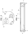
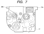
- Figs. 3 to 7 are projection views showing the process cartridge B (BY, BM, BC, BB).
- Fig. 3 is a front view
- Fig. 4 is a right side view
- Fig. 5 is a left side view
- Fig. 6 is a plan view
- Fig. 7 is a back view.
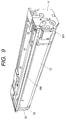
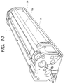
- Figs. 8 to 10 are perspective views of the appearance of the process cartridge B.
- Fig. 8 is a perspective view viewed from a front oblique side
- Fig. 9 is a perspective view viewed from a back oblique side
- Fig. 10 is a perspective view viewed from a back oblique side when a side of a bottom view is turned upward.
- the charging unit C makes the charging roller 8a, the regulating blade 8c and the electrically conductive brush 11 integral by the charging frame 13.
- the charging frame 13 constitutes a part of the exterior of the process cartridge B.
- a lower edge 13a of the charging frame 13 is close to the photosensitive drum 7 and made in parallel with the photosensitive drum 7 with a space along the longitudinal direction.
- a substantially vertical wall 13b is so disposed as to form the exterior of the process cartridge B from the lower edge 13a and then curved at the upper portion to form a corner portion 13c.
- a top plate portion 13d is extended substantially horizontally from the corner portion 13c and key-shaped in section.
- a space is defined below the top plate portion 13d, and member attaching portions 13e and 13f are formed integrally on both end portions thereof in the longitudinal direction as shown in Figs. 8 and 12.
- a horizontal member 25 is formed integrally with the charging frame 13 between the member attaching portions 13e and 13f.
- Fig. 11 is a side view of the charging unit C viewed from the inner side thereof.
- a charging roller bearing 22 and an end portion cover 23 are threaded together by a screw on one end of this side on the charging frame 13 in a direction of mounting the process cartridge B (mounted from the front of the apparatus main body 14 in the longitudinal direction).
- a gear unit 24 is fixedly threaded by a screw.
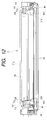
- Fig. 12 is a side view showing the charging unit C from which the regulating blade 8c and a support sheet metal 8d are removed.
- a blade attaching seat 13g formed by heightening the sides of the member attaching portions 13e and 13f by one step has a female screw 13h and a dowel 13i on a plane which is in contact with both ends of the regulating blade 8c, respectively, as shown in Fig. 12.
- a sealing material 21g such as sponge is stuck in the longitudinal direction onto the plane which retreats from the seat 13g.
- a sealing member 21b such as felt is stuck along the peripheral direction of a sealing portion 8al on each end portion of the charging roller 8a in order to prevent the developer from being leaked toward the exterior in the axial direction. Accordingly, a portion of the charging frame 13 opposite to the sealing portion 8al on each end portion of the charging roller 8a is arc-shaped concentrically with the charging roller 8a.
- the metal regulating blade 8c is arranged apart from the charging roller 8a with a space as shown in Fig. 2, and fixed onto the support sheet metal 8e by a small screw 8j.
- the support sheet metal 8d has a groove shape in section, and is fitted onto the dowel 13i of the seat 13g of the charging frame 13.
- the small screw 8k is threaded into the female screw 13h of the seat 13g through a hole of the support sheet metal 8d, as a result of which the support sheet metal 8d and the seat 13g are abutted against each other, and the sealing material 21g is compressed by the support sheet metal 8d.
- a portion close to the seat 13g of the sealing material 21b is compressed by the support sheet metal 8d.
- the support sheet metal 8d is extremely high in rigidity and both ends of the support sheet metal 8d are fixed to the charging frame 21 to stiffen the charging frame 21.
- the process cartridges BY to BB are mounted to the apparatus main body 14 by inserting the longitudinal guide portions 12a and 29b into guide rails (not shown) of the apparatus main body 14 from a direction perpendicular to a paper surface of Fig. 1. (Mounting of Charging Unit)
- the charging unit C is supported by the developing frame 12 so as to be pivotable about a pivot center SC as shown in Fig. 2.
- a cylindrical shaft portion 26a is disposed on the pivot center SC on a gear case 26 of a gear unit 24 which is fixed to one end of the charging frame 13 on the depth side of the longitudinal direction, and a cylindrical hole 23a is defined on the pivot center SC on the end portion cover 23 at the other end of the longitudinal direction.
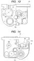
- the developing frame 12 receives the above-described agitating screws 10g and 10h on both sides of the partition wall 10f, and includes a lower portion 12f having a seat 12e for attaching the regulating blade 10e, a side portion 12g that forms a left exterior portion viewed from the mounting direction of the process cartridge B, and end plate portions 12h (on that side) and 12i (on this side) on both ends of the longitudinal direction as shown in Figs. 13, 14 and 17.
- One end plate portion 12h has a hole 12j for enabling the cylindrical shaft portion 26a of the charging unit C to rotate through a bearing.
- the other end plate portion 12i has a hole 12m identical in diameter with the hole 23a of the charging frame 13.
- the cylindrical fitting hole 23a of the charging unit C is allowed to align with the hole 12m of the end plate portion 12i of the developing frame 12 in a state where the cylindrical shaft portion 26a of the charging unit C is inserted into the hole 12j of the end plate portion 12h of the developing frame 12. Then, when positioning is made in such a manner that the rear cover 17 on that side viewed from the mounting direction of the process cartridge B aligns with the end portion of the developing frame 12, the outer periphery of a hollow cylindrical shaft support portion 17a (refer to Figs.
- the charging unit C is structured in such a manner that the cylindrical shaft portion 26a on one end side is rotatably supported by the rear cover 17 whereas the hole 23a on the other end side is rotatably supported by the developing frame 12.
- a top plate 29 is fixed onto the upper portion of the developing frame 12 by a small screw 28 so that the peripheral edge of the top plate 29 is abutted against the inner side of the guide portion 12a of the upper portion of the side portion 12g and the end plate portions 12h and 12i.
- two spring seats 29a are provided in the top plate 29 in two positions in the longitudinal direction. Compression coil springs 30 retained by the spring seats 29a are compressed and disposed between the top plate 29 and the charging frame 13. The charging unit C is urged by the spring force of the spring 30 clockwise about the pivot center SC in Fig. 2.
- a journal portion 8a2 formed by reducing the diameter of the end portion of the charging roller 8a and disposed around the rotating center of the charging roller 8a is provided with a charging SD spacer 8n as a space securing member for securing a space between the photosensitive drum 7 and the charging roller 8a.
- the charging SD spacer 8n is made up of a circular hole portion 8n1 and an arc-shaped portion 8n2. Also, the circular hole portion 8nl of the charging SD spacer 8n is rotatably fitted into the journal portion 8a2 of the charging roller 8a, and the arc-shaped portion 8n2 is in press contact with a region out of an image formable region of the photosensitive drum 7.
- a space is defined between the photosensitive drum 7 and the charging roller 8a, and the non-transferred toner which is going to pass through an opposite portion of the charging roller 8a and the photosensitive drum 7 is caught by making the moving direction of the peripheral surface of the charging roller 8a counter to the moving direction of the peripheral surface of the photosensitive drum 7 and applying the charging bias.
- the rotating direction A of the charging roller 8a is the same as the rotating direction B of the photosensitive drum 7, and the arc-shaped portion 8n2 of the charging SD spacer 8n extends upstream of the photosensitive drum 7 which is in contact with the arc-shaped portion 8n2 in the rotating direction.
- the extension portion 8n3 functions to prevent the charging SD spacer 8n from falling down due to the rotation of the photosensitive drum 7. Because the extension portion 8n3 side comes in contact with the photosensitive drum 7 and the photosensitive drum 7 rotates in a direction indicated by an arrow B, a frictional force of the photosensitive drum 7 and the arc-shaped portion 8n2 becomes large on the extension portion 8n3 side.
- an angle ⁇ shown in Fig. 19 is reduced. It is better if the angle ⁇ is a minus angle.
- the angle ⁇ is an angle formed by a tangent TL of the photosensitive drum 7 at a point P where the arc-shaped portion 8n2 initially enters the peripheral surface of the photosensitive drum 7 due to the movement of the peripheral surface of the photosensitive drum 7, and a straight line K connecting the point P and the center 08 of the charging roller 8a.
- an arc QP > an arc QR is satisfied.
- the point R is a point at that the peripheral surface of the photosensitive drum 7 leaves the arc-shaped portion 8n due to the movement of the peripheral surface of the photosensitive drum 7.
- the surface of the photosensitive drum 7 which is in contact with the arc-shaped portion 8n2 of the charging SD spacer 8n is made of aluminum, and the material of the charging SD spacer 8n is desirably polyether sulfone (PES) or polyphenylene sulfide (PPS) because of the high sliding property with respect to aluminum.
- PES polyether sulfone
- PPS polyphenylene sulfide
- the developing sleeve 10d is fitted to the developing frame 12 pivotably about the pressurizing center SLv.
- the journal portion 10d1 that reduces the diameter of both sides of the developing sleeve 10d is provided with the developing SD spacer 10j made up of the circular hole portion and the arc-shaped portion as the space securing member of the photosensitive drum 7 and the developing sleeve 10d.
- the developing SD spacer 10j is made up of the circular hole portion 10j1 and the arc-shaped portion 10j2 as shown in Fig. 19.
- the circular hole portion 10j1 of the developing SD spacer 10j is rotatably fitted into the journal portion 10d1 of the developing sleeve 10d, and the arc-shaped portion 10j2 is in press contact with a region out of an image formable region of the photosensitive drum 7.
- the outer side of the developing SD spacer 10j is provided with a pivotable arm 32 into which the journal 10d1 is fitted (refer to Figs. 17 and 18).
- Fig. 18 is a cross-sectional view showing a portion close to the side surface of the pivotable arm 32 which is perpendicular to the developing sleeve 10d.
- the base of the pivotable arm 32 is pivotably supported by a support shaft 33 which is press-fitted into both end plate portions 12h and 12i of the developing frame 12 in the longitudinal direction.
- a bearing hole 32a is defined substantially just above the support shaft 33 of the pivotable arm 32, and a stopper portion 32b is disposed above the bearing hole 32a.
- a spring seat 32c is disposed on a line substantially perpendicular to a line connecting the pressurizing center SLv which is the center of the support shaft 33 and the center of the bearing hole 32a.
- the journal portions 10d1 on both ends of the developing sleeve 10d are rotatably supported by the bearing holes 32a of the pivotable arms 32. Compression coil springs 35 are compressed and disposed between the spring seat 32c and the spring seats 12n disposed on the end plate portions 12h and 12i of the developing frame 12.
- the developing sleeve 10d rotates about the pressurizing center SLv and is pressurized toward the photosensitive drum 7, and the developing SD spacer 10j is in press contact with the end portions out of the image formable region of the photosensitive drum 7, to thereby keep a predetermined space (0.2 to 1.0 mm) between the developing sleeve 10d and the photosensitive drum 7.
- the rotating direction C of the developing sleeve 10d and the rotating direction B of the photosensitive drum 7 are counter so that the respective peripheral surfaces move in the opposite directions, and the arc-shaped portion 10j2 of the developing SD spacer 10j extends upstream of the photosensitive drum 7 which is in contact with the arc-shaped portion 10j2 in the moving direction of the peripheral surface of the photosensitive drum 7.
- the portion 10j3 functions to prevent the developing SD spacer 10j from falling down due to the rotation of the photosensitive drum 7.
- the arrangement of the arc-shaped portion 10j2 with respect to the photosensitive drum 7 is identical with the arrangement described with reference to the charging roller.
- the surface of the photosensitive drum 7 which is in contact with the arc-shaped portion 10j2 of the developing SD spacer 10j is made of aluminum, and the material of the developing SD spacer 10j is desirably polyether sulfone (PES) or polyphenylene sulfide (PPS) because of the high sliding property with respect to aluminum.
- PES polyether sulfone
- PPS polyphenylene sulfide
- the space securing member which is called "SD spacer" one side of which is a circular hole and the other side of which is arc is employed as the space securing member.
- the circular hole portion of the SD spacer is substantially identical in dimensions with the shaft end portion of the developing sleeve or the charging roller, and the arc portion is substantially identical in configuration with the outer diameter of the photosensitive drum.
- the circular hole portion of the SD spacer is rotatably fitted onto the shaft end portion of the developing roller or the charging roller, and the arc portion is abutted against the outer peripheral portion of the photosensitive drum. In this situation, the SD spacer is urged toward the abutment portion by a spring or the like as in the SD runner.
- the SD spacer can keep the SD gap, not while it rotates as in the SD runner, and even if the rotating directions of the photosensitive drum and the developing sleeve, or the rotating directions of the photosensitive drum and the charging roller are counter with respect to the moving directions of the respective peripheral surfaces, an influence of the peripheral speed difference is reduced as compared with a case using the SD runner. Also, because the arc portion is abutted against the photosensitive drum, which is not in contact like the SD runner at just one point but at an area, the surface pressure of the contact portion is reduced, and it becomes advantageous with respect to the wear of the SD spacer and the outer peripheral surface of the photosensitive drum, thereby being able to maintain the SD gap.
- the image forming apparatus is exemplified by a laser beam printer, but the present invention is not limited to this.
- the present invention is applicable to the image forming apparatus such as a copying machine, a facsimile machine or a word processor.
- the present invention does not need to be limited to the process cartridge exemplified in the above embodiments.
- the present invention may be used in the conventional image forming apparatus not using the process cartridge system.
- the present invention is not limited to the space securing member of the SD gap, but the present invention is also effective in the space securing member of another rotating cylindrical member such as the transfer roller.
- the space between two rotary members can be secured durably. Also, a space between the electrophotographic photosensitive drum and the developing sleeve, or a space between the photosensitive drum and the charging roller can be surely secured, to thereby contribute to an improvement in image quality.
- a space securing member that defines a predetermined space between the first rotary member and the second rotary member which is arranged apart from the first rotary member with the predetermined space, wherein the space securing member is provided with a circular hole which is rotatably supported by one of the first and second rotary members, and an arc-shaped portion which is in area contact with an outer peripheral surface of the other rotary member.
Abstract
Description
Compression coil springs 35 are compressed and disposed between the
Claims (13)
- A space securing member that defines a predetermined space between a first rotary member and a second rotary member which is arranged apart from said first rotary member with said predetermined space, wherein said space securing member is provided with a circular hole which is rotatably supported by one of said first and second rotary members, and an arc-shaped portion which is in area contact with a peripheral surface of the other of said first and second rotary members.
- A space securing member according to claim 1, wherein a moving direction of a peripheral surface of said first rotary member is counter to a moving direction of a peripheral surface of said second rotary member.
- A space securing member according to claim 1, wherein an arc shape of said arc-shaped portion is substantially complemental to the peripheral surface of the other of said first and second rotary members against which said space securing member is abutted.
- A space securing member according to claim 1, wherein said arc-shaped portion extends upstream of the peripheral surface of the other of said first and second rotary members in a moving direction so that said arc-shaped portion is not dragged by the other of said first and second rotary members which is in contact with said arc-shaped portion.
- A space securing member according to claim 1, wherein said space securing member is made of polyether sulfone (PES) or polyphenylene sulfide (PPS).
- A space securing member according to claim 1, wherein when a relationship between a diameter A of said first rotary member and a diameter B of said second rotary member satisfies A < B, said circular hole portion is fitted onto said first rotary member, and said arc-shaped portion is in contact with said second rotary member.
- A space securing member according to claim 1, wherein one of said first rotary member and said second rotary member comprises an electrophotographic photosensitive drum.
- A developing device for developing an electrostatic latent image formed on an electrophotographic photosensitive drum with toner, said developing device comprising:a developing roller; anda space securing member that defines a space between said developing roller and said electrophotographic photosensitive drum, said space securing member being rotatably supported by said developing roller and provided with an arc-shaped portion which is in area contact with an outer peripheral surface of said electrophotographic photosensitive drum.
- A charging device for charging an electrophotographic photosensitive drum, said charging device comprising:a charging roller; anda space securing member that defines a space between said charging roller and said electrophotographic photosensitive drum, said space securing member being rotatably supported by said charging roller and provided with an arc-shaped portion which is in area contact with an outer peripheral surface of said electrophotographic photosensitive drum.
- A process cartridge detachably mountable on a main body of an image forming apparatus, said process cartridge comprising:an electrophotographic photosensitive drum;a developing roller for developing an electrostatic latent image formed on said electrophotographic photosensitive drum with toner; anda space securing member that defines a space between said developing roller and said electrophotographic photosensitive drum, said space securing member being rotatably supported by said developing roller and provided with an arc-shaped portion which is in area contact with an outer peripheral surface of said electrophotographic photosensitive drum.
- A process cartridge detachably mountable on a main body of an image forming apparatus, said process cartridge comprising:an electrophotographic photosensitive drum;a charging roller for charging said electrophotographic photosensitive drum; anda space securing member that defines a space between said charging roller and said electrophotographic photosensitive drum, said space securing member being rotatably supported by said charging roller and provided with an arc-shaped portion which is in area contact with an outer peripheral surface of said electrophotographic photosensitive drum.
- A process cartridge detachably mountable on a main body of an image forming apparatus, said process cartridge comprising:an electrophotographic photosensitive drum;a developing roller for developing an electrostatic latent image formed on said electrophotographic photosensitive drum with toner;a space securing member that defines a space between said developing roller and said electrophotographic photosensitive drum, said space securing member being rotatably supported by said developing roller and provided with an arc-shaped portion which is in area contact with an outer peripheral surface of said electrophotographic photosensitive drum;a charging roller for charging said electrophotographic photosensitive drum; anda space securing member that defines a space between said charging roller and said electrophotographic photosensitive drum, said space securing member being rotatably supported by said charging roller and provided with an arc-shaped portion which is in area contact with an outer peripheral surface of said electrophotographic photosensitive drum.
- A process cartridge according to any one of claims 10 to 12, further comprising cleaning means for removing the toner remaining on said electrophotographic photosensitive drum after the toner has been transferred from said electrophotographic photosensitive drum.
Applications Claiming Priority (2)
| Application Number | Priority Date | Filing Date | Title |
|---|---|---|---|
| JP32910199 | 1999-11-19 | ||
| JP32910199A JP3679665B2 (en) | 1999-11-19 | 1999-11-19 | Gap assurance member, developing device, charging device, and process cartridge |
Publications (3)
| Publication Number | Publication Date |
|---|---|
| EP1102131A2 true EP1102131A2 (en) | 2001-05-23 |
| EP1102131A3 EP1102131A3 (en) | 2003-12-10 |
| EP1102131B1 EP1102131B1 (en) | 2008-10-08 |
Family
ID=18217628
Family Applications (1)
| Application Number | Title | Priority Date | Filing Date |
|---|---|---|---|
| EP00125002A Expired - Lifetime EP1102131B1 (en) | 1999-11-19 | 2000-11-16 | Space securing member, developing device, charging device and process cartridge |
Country Status (4)
| Country | Link |
|---|---|
| US (1) | US6385416B1 (en) |
| EP (1) | EP1102131B1 (en) |
| JP (1) | JP3679665B2 (en) |
| DE (1) | DE60040446D1 (en) |
Cited By (1)
| Publication number | Priority date | Publication date | Assignee | Title |
|---|---|---|---|---|
| WO2013022078A1 (en) * | 2011-08-05 | 2013-02-14 | Canon Kabushiki Kaisha | Process cartridge |
Families Citing this family (55)
| Publication number | Priority date | Publication date | Assignee | Title |
|---|---|---|---|---|
| JP2003162203A (en) * | 2001-09-13 | 2003-06-06 | Canon Inc | Unit, developing cartridge, process cartridge, toner cartridge, and electrophotographic image forming device |
| JP3969990B2 (en) * | 2001-10-10 | 2007-09-05 | キヤノン株式会社 | Developing device, process cartridge, and image forming apparatus |
| JP2003215917A (en) | 2002-01-24 | 2003-07-30 | Canon Inc | Developing device, process cartridge and image forming apparatus |
| JP4072362B2 (en) | 2002-03-14 | 2008-04-09 | キヤノン株式会社 | Developing device, process cartridge, and image forming apparatus |
| JP2004101690A (en) * | 2002-09-06 | 2004-04-02 | Canon Inc | Development device, process cartridge, and electrophotographic image forming apparatus |
| JP3944045B2 (en) | 2002-09-30 | 2007-07-11 | キヤノン株式会社 | Developer supply container and electrophotographic image forming apparatus |
| JP3913153B2 (en) * | 2002-09-30 | 2007-05-09 | キヤノン株式会社 | Power supply contact member, process cartridge, and image forming apparatus |
| JP3747195B2 (en) * | 2002-11-20 | 2006-02-22 | キヤノン株式会社 | Process cartridge and electrophotographic image forming apparatus |
| US6810221B1 (en) | 2003-04-24 | 2004-10-26 | Hewlett-Packard Development Company, L.P. | Apparatus and method for discharging an electrophotography component |
| JP3970217B2 (en) * | 2003-08-29 | 2007-09-05 | キヤノン株式会社 | Electrophotographic image forming apparatus |
| JP3782807B2 (en) * | 2003-11-28 | 2006-06-07 | キヤノン株式会社 | Process cartridge and method for attaching electrophotographic photosensitive drum |
| JP3840232B2 (en) * | 2004-05-06 | 2006-11-01 | キヤノン株式会社 | Process cartridge |
| JP3885074B2 (en) * | 2004-05-11 | 2007-02-21 | キヤノン株式会社 | Electrophotographic photosensitive drum, process cartridge, and electrophotographic image forming apparatus |
| JP4817682B2 (en) * | 2004-12-13 | 2011-11-16 | キヤノン株式会社 | Cleaning unit, process cartridge, and image forming apparatus |
| JP4865341B2 (en) * | 2005-02-04 | 2012-02-01 | キヤノン株式会社 | Process cartridge and electrophotographic image forming apparatus |
| JP4227626B2 (en) * | 2005-05-09 | 2009-02-18 | キヤノン株式会社 | Developer container, cartridge, and developer container manufacturing method |
| JP4681946B2 (en) | 2005-05-27 | 2011-05-11 | キヤノン株式会社 | Process cartridge, developing cartridge, and electrophotographic image forming apparatus |
| US20070138732A1 (en) * | 2005-12-21 | 2007-06-21 | Hackney Gary N | Roller separator for printers |
| JP4280770B2 (en) | 2006-01-11 | 2009-06-17 | キヤノン株式会社 | Process cartridge and electrophotographic image forming apparatus |
| JP4948382B2 (en) | 2006-12-22 | 2012-06-06 | キヤノン株式会社 | Coupling member for mounting photosensitive drum |
| JP4498407B2 (en) | 2006-12-22 | 2010-07-07 | キヤノン株式会社 | Process cartridge, electrophotographic image forming apparatus, and electrophotographic photosensitive drum unit |
| JP5311854B2 (en) | 2007-03-23 | 2013-10-09 | キヤノン株式会社 | Electrophotographic image forming apparatus, developing device, and coupling member |
| US8229320B2 (en) | 2007-05-15 | 2012-07-24 | Canon Kabushiki Kaisha | Electrophotographic image forming apparatus, cartridge, and cartridge holding member with lock and lock releasing members for releasably locking cartridge to the cartridge holding member |
| JP4458378B2 (en) | 2007-06-29 | 2010-04-28 | キヤノン株式会社 | Process cartridge and electrophotographic image forming apparatus |
| JP4458377B2 (en) | 2007-06-29 | 2010-04-28 | キヤノン株式会社 | Process cartridge and electrophotographic image forming apparatus |
| JP4968957B2 (en) | 2008-03-31 | 2012-07-04 | キヤノン株式会社 | Frame body unit, developing device and process cartridge, and frame body unit, developing device and process cartridge manufacturing method |
| JP5127565B2 (en) * | 2008-05-23 | 2013-01-23 | キヤノン株式会社 | Cartridge and image forming apparatus |
| JP5004870B2 (en) * | 2008-05-23 | 2012-08-22 | キヤノン株式会社 | Process cartridge and electrophotographic image forming apparatus |
| JP4558083B2 (en) | 2008-06-20 | 2010-10-06 | キヤノン株式会社 | Cartridge, method for assembling the cartridge, and method for disassembling the cartridge |
| JP5127584B2 (en) | 2008-06-20 | 2013-01-23 | キヤノン株式会社 | Drum unit and electrophotographic image forming apparatus |
| EP2333620A1 (en) | 2008-09-01 | 2011-06-15 | Canon Kabushiki Kaisha | Developing cartridge, process cartridge, and electrophotographic image forming apparatus |
| JP5335329B2 (en) * | 2008-09-01 | 2013-11-06 | キヤノン株式会社 | Image forming apparatus |
| JP5419584B2 (en) * | 2008-09-01 | 2014-02-19 | キヤノン株式会社 | Cartridge and electrophotographic image forming apparatus |
| JP5424749B2 (en) * | 2008-09-01 | 2014-02-26 | キヤノン株式会社 | cartridge |
| US8029284B2 (en) * | 2008-09-29 | 2011-10-04 | Maxillent Ltd. | Implants, tools, and methods for sinus lift and lateral ridge augmentation |
| US8322872B2 (en) * | 2009-08-20 | 2012-12-04 | Lexmark International, Inc. | Linear light diffusing structure for document scanners |
| JP5430349B2 (en) * | 2009-10-30 | 2014-02-26 | キヤノン株式会社 | Developer cartridge |
| JP5554963B2 (en) * | 2009-10-30 | 2014-07-23 | キヤノン株式会社 | Developing cartridge and process cartridge |
| JP5762054B2 (en) * | 2010-03-16 | 2015-08-12 | キヤノン株式会社 | Process cartridge and image forming apparatus |
| JP5106656B2 (en) | 2010-06-22 | 2012-12-26 | キヤノン株式会社 | Process cartridge and image forming apparatus |
| JP5284333B2 (en) | 2010-11-04 | 2013-09-11 | キヤノン株式会社 | Image forming apparatus |
| US9182733B2 (en) | 2013-02-07 | 2015-11-10 | Canon Kabushiki Kaisha | Developer supply cartridge, process cartridge and image forming apparatus |
| JP2015001602A (en) | 2013-06-14 | 2015-01-05 | キヤノン株式会社 | Development device, process cartridge and interval guarantee member |
| JP6512864B2 (en) | 2015-02-27 | 2019-05-15 | キヤノン株式会社 | Cartridge, process cartridge, image forming apparatus |
| CA3071424A1 (en) | 2015-02-27 | 2016-09-01 | Canon Kabushiki Kaisha | Cartridge |
| JP1536792S (en) * | 2015-03-31 | 2015-11-02 | ||
| JP1536790S (en) * | 2015-03-31 | 2015-11-02 | ||
| JP1536791S (en) * | 2015-03-31 | 2015-11-02 | ||
| JP1536793S (en) * | 2015-03-31 | 2015-11-02 | ||
| KR102533446B1 (en) | 2016-06-14 | 2023-05-16 | 캐논 가부시끼가이샤 | Process cartridge and electrophotographic image formation device |
| WO2018037574A1 (en) | 2016-08-26 | 2018-03-01 | キヤノン株式会社 | Cartridge and image forming device |
| JP6957205B2 (en) | 2017-05-31 | 2021-11-02 | キヤノン株式会社 | Cartridge and image forming equipment |
| JP7058992B2 (en) | 2017-12-13 | 2022-04-25 | キヤノン株式会社 | Image forming equipment and cartridge |
| SG11202005446QA (en) | 2017-12-13 | 2020-07-29 | Canon Kk | Cartridge and image forming apparatus |
| US10627780B2 (en) | 2018-01-23 | 2020-04-21 | Canon Kabushiki Kaisha | Cartridge and image forming apparatus |
Citations (5)
| Publication number | Priority date | Publication date | Assignee | Title |
|---|---|---|---|---|
| US4827305A (en) * | 1986-12-18 | 1989-05-02 | Minolta Camera Kabushiki Kaisha | Developing apparatus |
| JPH0862989A (en) * | 1994-08-26 | 1996-03-08 | Ricoh Co Ltd | Wet type developing device |
| US5666608A (en) * | 1996-05-02 | 1997-09-09 | Hewlett-Packard Company | Charging member and image forming member spacer apparatus |
| EP0907115A2 (en) * | 1997-10-01 | 1999-04-07 | Canon Kabushiki Kaisha | Process cartridge and electrophotographic image forming apparatus |
| JPH11223992A (en) * | 1998-02-09 | 1999-08-17 | Canon Inc | Space holding member and processing cartridge, developing device and image forming device using it |
Family Cites Families (38)
| Publication number | Priority date | Publication date | Assignee | Title |
|---|---|---|---|---|
| US4339196A (en) * | 1980-11-28 | 1982-07-13 | Pitney Bowes Inc. | Eccentric cam for electrophotocopier developer unit |
| JPS60128466A (en) * | 1983-12-16 | 1985-07-09 | Fuji Xerox Co Ltd | Non-magnetic one-component developing device |
| JPS6249157U (en) * | 1985-09-12 | 1987-03-26 | ||
| JPS62123651U (en) * | 1986-01-27 | 1987-08-06 | ||
| US4841330A (en) * | 1986-03-08 | 1989-06-20 | Konishiroku Photo Industry Co., Ltd. | Recording apparatus |
| JPH0435312Y2 (en) * | 1986-06-11 | 1992-08-21 | ||
| JPS63109949U (en) * | 1987-01-07 | 1988-07-15 | ||
| JPH0745096Y2 (en) * | 1988-11-14 | 1995-10-11 | 三田工業株式会社 | Image forming device |
| JPH03240076A (en) * | 1990-02-17 | 1991-10-25 | Canon Inc | Electrostatic charging device |
| JP3005114B2 (en) | 1991-07-19 | 2000-01-31 | キヤノン株式会社 | Cleaning device, process cartridge provided with the cleaning device, and image forming apparatus |
| US5585895A (en) | 1991-12-19 | 1996-12-17 | Canon Kabushiki Kaisha | Developing device and process cartridge with it |
| US5283616A (en) | 1991-12-19 | 1994-02-01 | Canon Kabushiki Kaisha | Developing device having bearing for supporting a developing roller |
| EP0586044B1 (en) | 1992-09-04 | 1997-03-26 | Canon Kabushiki Kaisha | Process cartridge, method for assembling process cartridge and image forming apparatus |
| MX9303563A (en) | 1992-09-04 | 1994-03-31 | Canon Kk | PROCESS CARTRIDGE, METHOD FOR ASSEMBLING A PROCESS CARTRIDGE AND IMAGE FORMING DEVICE. |
| JP3259985B2 (en) | 1992-09-04 | 2002-02-25 | キヤノン株式会社 | Process cartridge and image forming apparatus |
| US5966566A (en) | 1993-03-24 | 1999-10-12 | Canon Kabushiki Kaisha | Recycle method for process cartridge and image forming apparatus |
| JPH07209959A (en) * | 1994-01-24 | 1995-08-11 | Ricoh Co Ltd | Electrostatic charging device |
| KR0163809B1 (en) * | 1994-09-01 | 1999-03-20 | 켄지 히루마 | Image forming apparatus |
| JPH08123194A (en) * | 1994-10-22 | 1996-05-17 | Ricoh Co Ltd | Image forming device |
| CN1093946C (en) | 1995-07-21 | 2002-11-06 | 佳能株式会社 | Electrod assembly, developing device, processing card box and imaging equipment |
| US5768660A (en) * | 1995-08-02 | 1998-06-16 | Canon Kabushiki Kaisha | Charging device and process cartridge |
| JP3359245B2 (en) | 1995-10-25 | 2002-12-24 | キヤノン株式会社 | Process cartridge and electrophotographic image forming apparatus |
| JPH09213407A (en) | 1996-01-31 | 1997-08-15 | Canon Inc | Connector, unit, process cartridge and electrophotographic image forming device |
| JP3410275B2 (en) * | 1996-02-01 | 2003-05-26 | 株式会社リコー | Image forming device |
| JP3372747B2 (en) | 1996-02-09 | 2003-02-04 | キヤノン株式会社 | Developing device |
| JP3337915B2 (en) | 1996-07-04 | 2002-10-28 | キヤノン株式会社 | Process cartridge, method of assembling process cartridge, and image forming apparatus |
| JP3397590B2 (en) | 1996-07-04 | 2003-04-14 | キヤノン株式会社 | Process cartridge assembling method, process cartridge, and electrophotographic image forming apparatus |
| JP3969805B2 (en) | 1996-09-26 | 2007-09-05 | キヤノン株式会社 | Electrophotographic image forming apparatus |
| JPH10153938A (en) | 1996-09-26 | 1998-06-09 | Canon Inc | Electrophotographic image forming device and process cartridge |
| JP3969804B2 (en) | 1996-09-26 | 2007-09-05 | キヤノン株式会社 | Electrophotographic image forming apparatus |
| JP3352370B2 (en) | 1996-11-14 | 2002-12-03 | キヤノン株式会社 | Process cartridge and electrophotographic image forming apparatus |
| JP3327801B2 (en) | 1996-12-25 | 2002-09-24 | キヤノン株式会社 | Process cartridge, process cartridge assembling method, toner container assembling method, and electrophotographic image forming apparatus |
| JPH10222043A (en) | 1997-02-03 | 1998-08-21 | Canon Inc | Process cartridge and electrophotographic image forming device |
| JP3466888B2 (en) | 1997-10-01 | 2003-11-17 | キヤノン株式会社 | Process cartridge and electrophotographic image forming apparatus |
| JP3437424B2 (en) | 1997-10-27 | 2003-08-18 | キヤノン株式会社 | Developing device, process cartridge, and electrophotographic image forming device |
| US6157792A (en) | 1998-03-31 | 2000-12-05 | Canon Kabushiki Kaisha | Electrophotographic apparatus having plural image forming modes, and a process cartridge applied to such electrophotographic apparatus |
| JP3554200B2 (en) | 1998-08-31 | 2004-08-18 | キヤノン株式会社 | Process cartridge, image forming apparatus, and cleaning member mounting method |
| JP2000320537A (en) * | 1999-05-10 | 2000-11-24 | Minolta Co Ltd | Rotary unit holder device and image forming device using the rotary unit holder device |
-
1999
- 1999-11-19 JP JP32910199A patent/JP3679665B2/en not_active Expired - Fee Related
-
2000
- 2000-11-14 US US09/710,862 patent/US6385416B1/en not_active Expired - Lifetime
- 2000-11-16 EP EP00125002A patent/EP1102131B1/en not_active Expired - Lifetime
- 2000-11-16 DE DE60040446T patent/DE60040446D1/en not_active Expired - Lifetime
Patent Citations (5)
| Publication number | Priority date | Publication date | Assignee | Title |
|---|---|---|---|---|
| US4827305A (en) * | 1986-12-18 | 1989-05-02 | Minolta Camera Kabushiki Kaisha | Developing apparatus |
| JPH0862989A (en) * | 1994-08-26 | 1996-03-08 | Ricoh Co Ltd | Wet type developing device |
| US5666608A (en) * | 1996-05-02 | 1997-09-09 | Hewlett-Packard Company | Charging member and image forming member spacer apparatus |
| EP0907115A2 (en) * | 1997-10-01 | 1999-04-07 | Canon Kabushiki Kaisha | Process cartridge and electrophotographic image forming apparatus |
| JPH11223992A (en) * | 1998-02-09 | 1999-08-17 | Canon Inc | Space holding member and processing cartridge, developing device and image forming device using it |
Non-Patent Citations (2)
| Title |
|---|
| PATENT ABSTRACTS OF JAPAN vol. 1996, no. 07, 31 July 1996 (1996-07-31) & JP 8 062989 A (RICOH CO LTD), 8 March 1996 (1996-03-08) * |
| PATENT ABSTRACTS OF JAPAN vol. 1999, no. 13, 30 November 1999 (1999-11-30) & JP 11 223992 A (CANON INC), 17 August 1999 (1999-08-17) * |
Cited By (3)
| Publication number | Priority date | Publication date | Assignee | Title |
|---|---|---|---|---|
| WO2013022078A1 (en) * | 2011-08-05 | 2013-02-14 | Canon Kabushiki Kaisha | Process cartridge |
| CN103718115A (en) * | 2011-08-05 | 2014-04-09 | 佳能株式会社 | Process cartridge |
| US9377754B2 (en) | 2011-08-05 | 2016-06-28 | Canon Kabushiki Kaisha | Process cartridge |
Also Published As
| Publication number | Publication date |
|---|---|
| US6385416B1 (en) | 2002-05-07 |
| JP2001140857A (en) | 2001-05-22 |
| DE60040446D1 (en) | 2008-11-20 |
| JP3679665B2 (en) | 2005-08-03 |
| EP1102131A3 (en) | 2003-12-10 |
| EP1102131B1 (en) | 2008-10-08 |
Similar Documents
| Publication | Publication Date | Title |
|---|---|---|
| EP1102131B1 (en) | Space securing member, developing device, charging device and process cartridge | |
| US6442359B1 (en) | Process cartridge detachably mountable to a main assembly of an electrophotographic image forming apparatus comprising means for rotating a charging unit if first and second rotational directions and the apparatus mounting such a process cartridge | |
| US6289189B1 (en) | Process cartridge and electrophotographic image forming apparatus having a main assembly in which a cartridge coupling member is engageable with a main assembly coupling member to receive a driving force | |
| US6463233B2 (en) | Process cartridge having first and second cartridge guiding portions and an electrophotographic image forming apparatus to which the process cartridge is attached | |
| US7248810B2 (en) | Cartridge, process cartridge, and electrophotographic image forming apparatus | |
| US6608980B2 (en) | Electrophotographic image forming apparatus to which a process cartridge is detachably mountable and process cartridge comprising cartridge drum positioning portion or recess | |
| EP0433061B1 (en) | Process cartridge detachably mountable to image forming apparatus | |
| US8019259B2 (en) | Development device, process unit, and image forming apparatus | |
| US6181897B1 (en) | Developing apparatus | |
| US10551762B2 (en) | Image forming apparatus having guiding member for regulating approach of recording material toward transfer belt | |
| JP2014085633A (en) | Image forming apparatus | |
| US20150284197A1 (en) | Belt conveyance apparatus and image forming apparatus | |
| US8867971B2 (en) | Developer regulator, development device, and image forming apparatus incorporating same | |
| US6654583B2 (en) | Developing apparatus | |
| CN103913975A (en) | Image forming apparatus, and image forming unit and developing unit | |
| JP3406306B2 (en) | Image forming system | |
| US6813463B2 (en) | Belt device and image forming device using the same | |
| JP2003149951A (en) | Transfer belt meander prevention device and image forming device using the same | |
| US20210341037A1 (en) | Intermediate transfer belt structure to maintain axial distance between driving roller and backup roller | |
| US10365574B2 (en) | Image carrying member unit and image forming apparatus therewith | |
| US10372062B2 (en) | Developing apparatus and process cartridge | |
| JP2003186303A (en) | Gap-assuring member, developing device using the gap- assuring member, charging device and process cartridge detachable from image-forming apparatus | |
| JP2002108095A (en) | Developing roller and developing device provided with the same | |
| JP2002182541A (en) | Protection member, process cartridge, and image forming apparatus | |
| JP7433780B2 (en) | Image forming device |
Legal Events
| Date | Code | Title | Description |
|---|---|---|---|
| PUAI | Public reference made under article 153(3) epc to a published international application that has entered the european phase |
Free format text: ORIGINAL CODE: 0009012 |
|
| AK | Designated contracting states |
Kind code of ref document: A2 Designated state(s): AT BE CH CY DE DK ES FI FR GB GR IE IT LI LU MC NL PT SE TR |
|
| AX | Request for extension of the european patent |
Free format text: AL;LT;LV;MK;RO;SI |
|
| PUAL | Search report despatched |
Free format text: ORIGINAL CODE: 0009013 |
|
| AK | Designated contracting states |
Kind code of ref document: A3 Designated state(s): AT BE CH CY DE DK ES FI FR GB GR IE IT LI LU MC NL PT SE TR |
|
| AX | Request for extension of the european patent |
Extension state: AL LT LV MK RO SI |
|
| 17P | Request for examination filed |
Effective date: 20040427 |
|
| AKX | Designation fees paid |
Designated state(s): DE FR GB IT |
|
| 17Q | First examination report despatched |
Effective date: 20060719 |
|
| GRAP | Despatch of communication of intention to grant a patent |
Free format text: ORIGINAL CODE: EPIDOSNIGR1 |
|
| GRAS | Grant fee paid |
Free format text: ORIGINAL CODE: EPIDOSNIGR3 |
|
| GRAA | (expected) grant |
Free format text: ORIGINAL CODE: 0009210 |
|
| AK | Designated contracting states |
Kind code of ref document: B1 Designated state(s): DE FR GB IT |
|
| REG | Reference to a national code |
Ref country code: GB Ref legal event code: FG4D |
|
| REF | Corresponds to: |
Ref document number: 60040446 Country of ref document: DE Date of ref document: 20081120 Kind code of ref document: P |
|
| PLBE | No opposition filed within time limit |
Free format text: ORIGINAL CODE: 0009261 |
|
| STAA | Information on the status of an ep patent application or granted ep patent |
Free format text: STATUS: NO OPPOSITION FILED WITHIN TIME LIMIT |
|
| PG25 | Lapsed in a contracting state [announced via postgrant information from national office to epo] |
Ref country code: IT Free format text: LAPSE BECAUSE OF FAILURE TO SUBMIT A TRANSLATION OF THE DESCRIPTION OR TO PAY THE FEE WITHIN THE PRESCRIBED TIME-LIMIT Effective date: 20081008 |
|
| 26N | No opposition filed |
Effective date: 20090709 |
|
| REG | Reference to a national code |
Ref country code: FR Ref legal event code: ST Effective date: 20111209 |
|
| PG25 | Lapsed in a contracting state [announced via postgrant information from national office to epo] |
Ref country code: FR Free format text: LAPSE BECAUSE OF NON-PAYMENT OF DUE FEES Effective date: 20081208 |
|
| PGFP | Annual fee paid to national office [announced via postgrant information from national office to epo] |
Ref country code: GB Payment date: 20171130 Year of fee payment: 18 |
|
| PGFP | Annual fee paid to national office [announced via postgrant information from national office to epo] |
Ref country code: DE Payment date: 20180131 Year of fee payment: 18 |
|
| REG | Reference to a national code |
Ref country code: DE Ref legal event code: R119 Ref document number: 60040446 Country of ref document: DE |
|
| GBPC | Gb: european patent ceased through non-payment of renewal fee |
Effective date: 20181116 |
|
| PG25 | Lapsed in a contracting state [announced via postgrant information from national office to epo] |
Ref country code: DE Free format text: LAPSE BECAUSE OF NON-PAYMENT OF DUE FEES Effective date: 20190601 |
|
| PG25 | Lapsed in a contracting state [announced via postgrant information from national office to epo] |
Ref country code: GB Free format text: LAPSE BECAUSE OF NON-PAYMENT OF DUE FEES Effective date: 20181116 |