EP1102089A2 - Verfahren und Vorrichtung zum Bestimmen des Abstands zu einem Objekt mittels eines gepulsten elektromagnetischen Signals - Google Patents
Verfahren und Vorrichtung zum Bestimmen des Abstands zu einem Objekt mittels eines gepulsten elektromagnetischen Signals Download PDFInfo
- Publication number
- EP1102089A2 EP1102089A2 EP00105341A EP00105341A EP1102089A2 EP 1102089 A2 EP1102089 A2 EP 1102089A2 EP 00105341 A EP00105341 A EP 00105341A EP 00105341 A EP00105341 A EP 00105341A EP 1102089 A2 EP1102089 A2 EP 1102089A2
- Authority
- EP
- European Patent Office
- Prior art keywords
- signal
- delayed
- mixer
- transmission signal
- sweep
- Prior art date
- Legal status (The legal status is an assumption and is not a legal conclusion. Google has not performed a legal analysis and makes no representation as to the accuracy of the status listed.)
- Granted
Links
- 238000000034 method Methods 0.000 title claims abstract description 30
- 230000005540 biological transmission Effects 0.000 claims abstract description 72
- 230000003111 delayed effect Effects 0.000 claims abstract description 52
- 238000001228 spectrum Methods 0.000 claims abstract description 27
- 230000000052 comparative effect Effects 0.000 claims abstract description 16
- 238000005259 measurement Methods 0.000 claims description 9
- 230000001960 triggered effect Effects 0.000 claims description 4
- 230000002596 correlated effect Effects 0.000 claims description 2
- 230000008878 coupling Effects 0.000 abstract description 11
- 238000010168 coupling process Methods 0.000 abstract description 11
- 238000005859 coupling reaction Methods 0.000 abstract description 11
- 230000000694 effects Effects 0.000 abstract description 6
- 238000001208 nuclear magnetic resonance pulse sequence Methods 0.000 description 4
- 238000005070 sampling Methods 0.000 description 4
- 238000001514 detection method Methods 0.000 description 3
- 230000008901 benefit Effects 0.000 description 2
- 239000003990 capacitor Substances 0.000 description 2
- 230000000875 corresponding effect Effects 0.000 description 2
- 238000001914 filtration Methods 0.000 description 2
- 239000000203 mixture Substances 0.000 description 2
- 230000008569 process Effects 0.000 description 2
- 230000000717 retained effect Effects 0.000 description 2
- 230000004913 activation Effects 0.000 description 1
- 230000003044 adaptive effect Effects 0.000 description 1
- 230000002411 adverse Effects 0.000 description 1
- 230000008859 change Effects 0.000 description 1
- 238000013016 damping Methods 0.000 description 1
- 230000006866 deterioration Effects 0.000 description 1
- 230000010363 phase shift Effects 0.000 description 1
- 230000009467 reduction Effects 0.000 description 1
- 238000011144 upstream manufacturing Methods 0.000 description 1
Images



Classifications
-
- G—PHYSICS
- G01—MEASURING; TESTING
- G01S—RADIO DIRECTION-FINDING; RADIO NAVIGATION; DETERMINING DISTANCE OR VELOCITY BY USE OF RADIO WAVES; LOCATING OR PRESENCE-DETECTING BY USE OF THE REFLECTION OR RERADIATION OF RADIO WAVES; ANALOGOUS ARRANGEMENTS USING OTHER WAVES
- G01S13/00—Systems using the reflection or reradiation of radio waves, e.g. radar systems; Analogous systems using reflection or reradiation of waves whose nature or wavelength is irrelevant or unspecified
- G01S13/02—Systems using reflection of radio waves, e.g. primary radar systems; Analogous systems
- G01S13/06—Systems determining position data of a target
- G01S13/08—Systems for measuring distance only
- G01S13/10—Systems for measuring distance only using transmission of interrupted, pulse modulated waves
-
- G—PHYSICS
- G01—MEASURING; TESTING
- G01S—RADIO DIRECTION-FINDING; RADIO NAVIGATION; DETERMINING DISTANCE OR VELOCITY BY USE OF RADIO WAVES; LOCATING OR PRESENCE-DETECTING BY USE OF THE REFLECTION OR RERADIATION OF RADIO WAVES; ANALOGOUS ARRANGEMENTS USING OTHER WAVES
- G01S7/00—Details of systems according to groups G01S13/00, G01S15/00, G01S17/00
- G01S7/02—Details of systems according to groups G01S13/00, G01S15/00, G01S17/00 of systems according to group G01S13/00
- G01S7/28—Details of pulse systems
- G01S7/285—Receivers
Definitions
- the present invention relates to a method for Determining the distance to an object using a pulsed electromagnetic signal, the running time of the signal to the object and back again as part of a comparative measurement principle by comparing the Receive signal with a variable delay delayed transmission signal determined and from the determined Runtime the distance to the object is determined, and where within the framework of the comparative measurement principle Receive signal in a homodyne mixer with the delayed transmission signal is mixed.
- the invention also relates to a device for determining the Distance to an object by means of a pulsed electromagnetic signal, the device means to determine the transit time of the signal to the object and back again within the framework of a comparative measuring principle by comparing the received signal with the one variable delay delayed transmission signal, means for Determining the distance to the object from the determined Runtime and a homodyne mixer to mix the Receive signal within the framework of the comparative measurement principle with the delayed transmission signal.
- Such methods are used, for example, for radar parking aids or with radar distance control devices in the Automotive area used.
- Such a process is, for example, from German patent application DE 199 19 227 known.
- ETS equivalent time Sampling
- This will be Receive signal with a variable delay delayed transmission signal compared.
- the measuring principle is the extremely short pulse running times of the Signals stretched to a much longer time scale. This is done by slowly changing the internal Delay of the transmission pulse sequence specified, this is Delay over the real runtime range to be measured pushes.
- the received signal From the comparison of the internally delayed pulse train of the delayed transmission signal with the received pulse sequence the received signal becomes the external transit time and thereby the distance to the object determines.
- the homodyne mixer is preferably as one High-frequency mixer trained.
- the output signal is or the spectrum of the output signal of the homodyne Mixer not DC-free. Accordingly, the high pass coupling leads (Fig. 5) to a distortion and widening of original waveform in the time domain (Fig. 7). The Amplitude of the high-pass coupled output signal reduced and the signal pulse broadened. That leads to lingering and deteriorated resolution in the subsequent signal processing. If in one large useful signal also contains smaller useful signals, this increases the risk that the smaller useful signals not distinguished as such from the large useful signal can be.
- the pulse width of the mixer output signal is u. a. the pulse width of the high-frequency pulses of the transmission signal and the sweep speed with which the delay of the transmission signal is varied, depending.
- the short ones Radio frequency pulses are generated with a conversion factor that from the ratio of the speed of light to that Sweep speed results in the stretched equivalent Time level of the pulses of the mixer output signal implemented. It is therefore possible to determine the implementation factor thereby reducing the sweep speed is chosen relatively large. This will change the pulse width of the Output signal reduced in the time plane and that Spectrum of the pulses spread further. The result is that the relative part of the signal spectrum, which by the High pass is suppressed, is reduced.
- the invention suggests of the procedure of the type mentioned above that the Transmission signal and / or the delayed transmission signal with a predetermined frequency that the Spectrum of the mixer output signal to a higher Non-zero frequency level is raised.
- the spectrum of the mixer output signal is reduced to one higher frequency level raised that of the opposite frequency corresponds.
- the predetermined frequency is preferred greater than the frequency of the sweep signal and less than the pulse repetition frequency (PRF) of the transmission signal.
- PRF pulse repetition frequency
- the time difference between the pulses of the transmission signal and the pulses of the delayed transmission signal can be on can be modulated in different ways. For example, it is conceivable the transmission signal and / or the delayed transmission signal to modulate accordingly.
- the received signal points the same frequency as the transmission signal and is opposite the transmission signal only by the signal transit time to the Object and back delayed.
- a modulation of the Transmitted signal thus also affects the received signal out.
- modulating the transmission signal and / or the delayed transmission signal becomes the output signal of the Mixer in which the received signal with the delayed Broadcast signal is mixed, changed so that the Spectrum of the output signal at the higher frequency level is raised not equal to zero.
- the transmission signal by means of a first delay element, the delay of which means of a sweep signal is varied to the delayed Transmission signal is delayed with the variable delay, whereby the sweep signal is varied.
- the Sweepsignals can be the delayed broadcast signal on simple and be modulated effectively.
- control signal can be the transmission signal and so that the received signal is simple and effective Be modulated.
- the sweep signal and / or the control signal is advantageously a modulated rectangular signal.
- the sweep signal and / or the control signal Sinus signal is modulated.
- the present invention proposes that Sweep signal and / or the control signal between its actual value and a different value is switched.
- the one of the real value the deviating value is preferably a negative value.
- the deviating value of the sweep signal and / or the Control signal is advantageously selected in such a way that the output signal of the mixer to the corresponding one Time is equal to or almost zero.
- the output signal the mixer is thus between its actual value and switched to a value equal to or almost zero.
- This Embodiment has the advantage that the output signal from its actual value to a defined, constant value is switched and thereby the envelope of the mixer output signal is retained.
- Sweep signal and / or the control signal between its actual value and another value switched is chosen such that the pulses of the Transmission signal in time after the pulses of the delayed Transmission signal are triggered. If the pulse of the Transmission signal in time after the pulses of the delayed Can be assumed be that the output signal should be zero because the detection of an object or the distance measurement to the Object is not possible. This way too the output signal of the mixer between its actual value and a value equal to zero switched become.
- the present invention proposes that Sweep signal and / or the control signal by means of a D / A converter modulated or encoded by a microcomputer and the output signal of the mixer from the Microcomputer is read. In the microcomputer the output signal is then demodulated, decoded or correlated.
- a D / A converter modulated or encoded by a microcomputer
- the output signal is then demodulated, decoded or correlated.
- PWM pulse width modulation
- FM Frequency modulation
- certain types of coding or certain correlation techniques for the invention Procedures are used.
- the invention proposed that the predetermined frequency, with which the transmission signal and / or the delayed transmission signal is modulated, is also modulated.
- Fig. 1 is a device for determining the distance to an object by means of a pulsed electromagnetic Signals in their entirety with reference number 1 characterized.
- Devices of that shown in Fig. 1 Type become, for example, with radar parking aids or with radar distance control devices in the automotive sector used.
- From the device 1 is a pulsed electromagnetic signal 2 in the direction of an object 3 sent out.
- the transit time of signal 2 to object 3 and will be back again as part of a comparative Measuring principle, which in the specialist literature as equivalent time Sampling (ETS) method is known, measured.
- ETS equivalent time Sampling
- the measurement principle becomes a received signal 4 in a homodyne Mixer with a variable in the device 1 Delay delayed transmission signal 5 or with the Carrier signal of the transmission signals 2, 5 mixed. From the The determined runtime then becomes the distance to object 3 certainly.
- the device 1 comprises a microcomputer 6, which controls the execution of the method according to the invention.
- the microcomputer 6 has a variety of D / A and A / D converter with the analog components of device 1 connected.
- the carrier signal 8 is in an oscillator 7 the transmission signal 2, 5 generated.
- a power divider 9 is the carrier signal 8 in a carrier signal 10 for the Transmit signal 2 and in a carrier signal 11 for the delayed Transmission signal 5 split.
- the carrier signal 10 is in an attenuator 12 with one from the microcomputer 6 damping predetermined.
- the microcomputer 6 controls a pulse repetition generator 13 which outputs a pulse trigger signal 14.
- the Pulse trigger signal 14 is sent to a delay element 15 performed, the delay from the microcomputer 6 by means of of a sweep signal 16 can be varied.
- the Pulse trigger signal 14 as well as the delayed one Pulse trigger signal 17 are each a pulse shaper 48; 49 fed.
- the pulse shapers 48, 49 enable the selection of one variable pulse length of the envelope of the Amplitude modulation of the carrier signal 8.
- the microcomputer 6 has access to the pulse shapers 48 via a D / A converter, 49 and can thus determine the pulse width of the pulses of the transmission signals 2 and select the delayed transmission signals 5.
- the output signal 19 of the pulse shaper 48 is used for Activation of a first analog modulation switch 20, through which the pulses of the output signal 19 to the Carrier signal 10 are modulated and so the transmission signal 2 is formed.
- the output signal 21 of the pulse shaper 49 is used to control a second analog Modulation switch 22 through which the pulses of the Output signal 21 modulated onto the carrier signal 11 are and so the delayed transmission signal 5 is formed.
- the switches 20, 22 are fast high-frequency switches educated. The time of triggering a pulse is carried out by the pulse trigger signals 14, 17, which the Trigger pulse shaper 48, 49.
- the transmission signal 2 is from the device 1 by means of a Transmitting antenna 23 emitted in the direction of the object 3, from this at least partially reflected and from the Device 1 by means of a receiving antenna 24 again receive.
- the received signal 4 is in an amplifier 25 amplified and by a first signal switch 26 in two identical signals 27, 28 divided. That was delayed Transmitted signal 5 is from a second switch 29 also divided into two signals 30, 31, the Signal 31 by -90 ° (-PI / 2) relative to signal 30 is out of phase.
- This two-channel process is in in the literature known as I / Q measurement.
- a first homodyne radio frequency (HF) mixer 32 signals 27 and 30 become the same on one frequency level Zero and in a second homodyne radio frequency (HF) mixer 33 the signals 28 and 31 also on a Frequency level mixed to zero.
- the output signals 34, 35 of the HF mixer 32, 33 are via adaptive signal filters 36, 37 and variable amplifiers 38, 39 to the microcomputer 6 led.
- the in the path of the output signals 34, 35 of the RF mixer 32, 33 arranged signal filters 36, 37 and amplifier 38, 39 are usually DC-free via coupling capacitors interconnected (so-called high pass coupling). This is necessary to eliminate offset drifts and Suppress sources of interference in the low-frequency range can.
- 3 to 7 relate to one from the prior art Device known in the art for determining the distance to an object by means of a pulsed electromagnetic Signal.
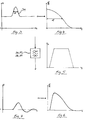
- 3 is the waveform of the output signal 34 after a homodyne mix on a frequency level represented zero. Everything below for that Output signal 34 is said also applies to that Output signal 35.
- Fig. 4 shows the spectrum of the Output signal 34 from FIG. 3. As in FIGS. 3 and 4 is shown, the output signal 34 (Fig. 3) of the homodyne Mixer 32 or the spectrum (Fig. 4) of the output signal 34 not DC-free. Accordingly, high pass coupling results (see Fig.
- FIG. 7 it can be clearly seen that the amplitude of the high-pass coupled output signal 34 and reduced Signal pulse is broadened. This leads to a reverberation and deteriorated resolution at subsequent signal processing in the microcomputer 6. If there are smaller useful signals in a large useful signal are included, the risk increases that the smaller useful signals not as such from the big one Can distinguish useful signal. That can be done with the Device known from the prior art cause smaller objects to be monitored in one Area in front of or behind a motor vehicle undetected stay.
- the RF mixer 32, 33 are subordinate to the output signals 34, 35 of the HF mixer 32, 33 to reduce or even avoid altogether, without using a heterodyne radio frequency (RF) system
- the invention proposes to transmit signal 2 and / or the delayed transmission signal 5 with a modulate the predetermined frequency such that the Spectra of the output signals 34, 35 of the mixers 32, 33 a higher frequency level is raised to non-zero.
- Distortion and broadening of the high-pass coupled Output signals 34, 35 can be avoided.
- the time difference between the pulses of the transmission signal 2 and the pulses of the delayed transmission signal 5 are modulated.
- the first exemplary embodiment is shown in FIG. 1 proposed to vary the sweep signal 16.
- the sweep signal 16 can be an example of this Rectangular signal can be modulated.
- the result is that the output signals 34, 35 of the RF mixer 32, 33 between their actual value at the current time and a value toggled at a previous time become. So in the end the gradients of the Output signals 34, 35 considered.
- the Sweep signal 16 also a sine signal or another Waveform can be modulated.
- the sweep signal 16 between its actual value and another value is switched.
- the further value is chosen in such a way that the pulses of the transmission signal 2 are timed after the pulses of the delayed transmission signal 5 are triggered. If the Pulse of the transmission signal 2 in time after the pulses of the delayed transmission signal 5 can be triggered be assumed that the output signals 34, 35 are the same Should be zero since the detection of an object 3 or the distance measurement to object 3 is not possible. Also in this way the output signals 34, 35 of the RF mixer 32, 33 between their actual value and one Value equal to zero can be switched.
- FIG. 2 is a section of a for simplification single channel device 1, d. H. no I / Q system like in Fig. 1, shown with only one output path.
- another Delay element 50 is arranged in the transmission path of the transmission signal 2 in the transmission path of the transmission signal 2 . More specifically, it is further delay element 50 in the path of the Pulse trigger signal 14 arranged and delayed that Output signal 19 of the pulse shaper 48, through which the Modulation switch 20 is controlled to a variable Delay.
- the delay of the further Delay element 50 is activated by means of a control signal 51 varies.
- the control signal 51 can as above in the context of 1 for the sweep signal 16 can be varied.
- the variation of the control signal 51 can in addition to or instead of the variation of the sweep signal 16 can be performed.
- the modulation according to the invention contributes Using a square wave signal to modulate the Transmission signal 2 and / or the delayed transmission signal 5 a Pulse amplitude modulation (PAM) of the output signals 34, 35 by.
- the output signals 34, 35 form the modulating source signals (Fig. 8), the spectra of which Pointer of the first harmonic of the square wave signal 46 (Fig. 9) can be folded.
- the square wave signal is between a current value and a different value switched, in which the output signal 34; 35 of Mixer 32; 33 is zero.
- the pointers are obtained as Coefficients of the Fourier series of the square wave signal 46.
Landscapes
- Engineering & Computer Science (AREA)
- Radar, Positioning & Navigation (AREA)
- Remote Sensing (AREA)
- Computer Networks & Wireless Communication (AREA)
- Physics & Mathematics (AREA)
- General Physics & Mathematics (AREA)
- Radar Systems Or Details Thereof (AREA)
Abstract
Description
- Fig. 1
- eine Vorrichtung zur Durchführung des erfindungsgemäßen Verfahrens gemäß eines ersten bevorzugten Ausführungsbeispiels;
- Fig. 2
- eine Vorrichtung im Ausschnitt zur Durchführung des erfindungsgemäßen Verfahrens gemäß eines zweiten bevorzugten Ausführungsbeispiels;
- Fig. 3
- einen Signalpuls eines Ausgangssignals eines homodynen Mischers einer aus dem Stand der Technik bekannten Vorrichtung zum Bestimmen des Abstands zu einem Objekt mittels des Equivalent Time Sampling (ETS)-Verfahrens;
- Fig. 4
- das Spektrum des Signalpulses aus Fig. 3;
- Fig. 5
- das Spektrum eines Hochpassfilters;
- Fig. 6
- das hochpassgefilterte Spektrum aus Fig. 4;
- Fig. 7
- der Signalpuls aus Fig. 3 nach der Hochpassfilterung;
- Fig. 8
- einen Signalpuls eines Ausgangssignals des homodynen Mischers der Vorrichtung gemäß Fig. 2;
- Fig. 9
- ein Signal zur Modulation der Zeitdifferenz, d. h. des Sweepsignals und/oder des Ansteuersignals der Vorrichtung gemäß Fig. 2;
- Fig. 10
- der Signalpuls gemäß Fig. 8 nach einer Modulation durch das Signal gemäß Fig. 9;
- Fig. 11
- das Spektrum des modulierten Signalpuls gemäß Fig. 10; und
- Fig. 12
- das auf die erste Harmonische gefilterte Spektrum gemäß Fig. 11.
Claims (12)
- Verfahren zum Bestimmen des Abstands zu einem Objekt (3) mittels eines gepulsten elektromagnetischen Signals (2), wobei die Laufzeit des Signals (2) zu dem Objekt (3) und wieder zurück im Rahmen eines vergleichenden Messprinzips durch Vergleich des Empfangssignals (4) mit dem um eine variable Verzögerung verzögerten Sendesignal (5) ermittelt und aus der ermittelten Laufzeit der Abstand zu dem Objekt (3) bestimmt wird, und wobei im Rahmen des vergleichenden Messprinzips das Empfangssignal (4) in einem homodynen Mischer (32; 33) mit dem verzögerten Sendesignal (5) gemischt wird, dadurch gekennzeichnet, dass das Sendesignal (2) und/oder das verzögerte Sendesignal (5) derart mit einer vorgegebenen Frequenz moduliert werden, dass das Spektrum des Ausgangssignals (34; 35) des Mischers (32; 33) auf eine höhere Frequenzebene ungleich Null angehoben wird.
- Verfahren nach Anspruch 1, dadurch gekennzeichnet, dass die Zeitdifferenz zwischen den Pulsen des Sendesignals (2) und den Pulsen des verzögerten Sendesignals (5) moduliert wird.
- Verfahren nach Anspruch 2, dadurch gekennzeichnet, dass das Sendesignal (2) mittels eines ersten Verzögerungsglieds (15), dessen Verzögerung mittels eines Sweepsignals (16) variiert wird, zu dem verzögerten Sendesignal (5) mit der variablen Verzögerung verzögert wird, wobei das Sweepsignal (16) variiert wird.
- Verfahren nach Anspruch 2 oder 3, dadurch gekennzeichnet, dass in dem Sendepfad des Sendesignals (2) ein weiteres Verzögerungsglied angeordnet ist, dessen Verzögerung mittels eines Ansteuersignals (51) variiert wird, wobei das Ansteuersignal (51) variiert wird.
- Verfahren nach Anspruch 3 oder 4, dadurch gekennzeichnet, dass dem Sweepsignal (16) und/oder dem Ansteuersignal (51) ein Rechtecksignal aufmoduliert wird.
- Verfahren nach Anspruch 3 oder 4, dadurch gekennzeichnet, dass dem Sweepsignal (16) und/oder dem Ansteuersignal (51) ein Sinussignal aufmoduliert wird.
- Verfahren nach Anspruch 3 oder 4, dadurch gekennzeichnet, dass das Sweepsignal (16) und/oder das Ansteuersignal (51) zwischen seinem eigentlichen Wert und einem davon abweichenden Wert umgeschaltet wird.
- Verfahren nach Anspruch 7, dadurch gekennzeichnet, dass der von dem eigentlichen Wert abweichende Wert des Sweepsignals (16) und/oder des Ansteuersignals (51) derart gewählt wird, dass das Ausgangssignal des Mischers (32; 33) gleich oder nahezu Null ist.
- Verfahren nach Anspruch 3 oder 4, dadurch gekennzeichnet, dass das Sweepsignal (16) und/oder das Ansteuersignal (51) zwischen seinem eigentlichen Wert und einem weiteren Wert umgeschaltet wird, der derart gewählt wird, dass die Pulse des Sendesignals (2) zeitlich nach den Pulsen des verzögerten Sendesignals (5) ausgelöst werden.
- Verfahren nach Anspruch 3 oder 4, dadurch gekennzeichnet, dass das Sweepsignal (16) und/oder das Ansteuersignal (51) mittels eines D/A-Wandlers von einem Mikrocomputer (6) moduliert oder codiert wird und das Ausgangssignal (34; 35) des Mischers (32; 33) von dem Mikrocomputer (6) eingelesen und demoduliert, decodiert oder korreliert wird.
- Verfahren nach einem der Ansprüche 1 bis 10, dadurch gekennzeichnet, dass die vorgegebene Frequenz, mit der das Sendesignal (2) und/oder das verzögerte Sendesignal (5) moduliert werden, moduliert wird.
- Vorrichtung (1) zum Bestimmen des Abstands zu einem Objekt (3) mittels eines gepulsten elektromagnetischen Signals (2), wobei die Vorrichtung (1) Mittel (6, 25, 26, 36, 37, 38, 39) zum Ermitteln der Laufzeit des Signals (2) zu dem Objekt (3) und wieder zurück im Rahmen eines vergleichenden Messprinzips durch Vergleich des Empfangssignals (4) mit dem um eine variable Verzögerung verzögerten Sendesignal (5), Mittel (6) zum Bestimmen des Abstands zu dem Objekt (3) aus der ermittelten Laufzeit und einen homodynen Mischer (32; 33) zum Mischen des Empfangssignals (4) im Rahmen des vergleichenden Messprinzips mit dem verzögerten Sendesignal (5) aufweist, dadurch gekennzeichnet, dass die Vorrichtung (1) Mittel (40, 41, 43; 44, 45) zum Durchführen des Verfahrens nach einem der Ansprüche 1 bis 11 aufweist.
Applications Claiming Priority (2)
| Application Number | Priority Date | Filing Date | Title |
|---|---|---|---|
| DE1999155638 DE19955638A1 (de) | 1999-11-20 | 1999-11-20 | Verfahren und Vorrichtung zum Bestimmen des Abstands zu einem Objekt mittels eines gepulsten elektromagnetischen Signals |
| DE19955638 | 1999-11-20 |
Publications (3)
| Publication Number | Publication Date |
|---|---|
| EP1102089A2 true EP1102089A2 (de) | 2001-05-23 |
| EP1102089A3 EP1102089A3 (de) | 2003-10-22 |
| EP1102089B1 EP1102089B1 (de) | 2009-04-01 |
Family
ID=7929576
Family Applications (1)
| Application Number | Title | Priority Date | Filing Date |
|---|---|---|---|
| EP00105341A Expired - Lifetime EP1102089B1 (de) | 1999-11-20 | 2000-03-16 | Verfahren und Vorrichtung zum Bestimmen des Abstands zu einem Objekt mittels eines gepulsten elektromagnetischen Signals |
Country Status (2)
| Country | Link |
|---|---|
| EP (1) | EP1102089B1 (de) |
| DE (2) | DE19955638A1 (de) |
Family Cites Families (8)
| Publication number | Priority date | Publication date | Assignee | Title |
|---|---|---|---|---|
| US4049953A (en) * | 1976-06-24 | 1977-09-20 | The United States Of America, As Represented By The Secretary Of The Navy | Complex pulse repetition frequency generator |
| DE3321224A1 (de) * | 1983-06-11 | 1984-12-13 | Licentia Patent-Verwaltungs-Gmbh, 6000 Frankfurt | Millimeterwellen-radargeraet zur messung kurzer entfernungen |
| DE4127168C2 (de) * | 1991-08-16 | 1994-07-07 | Spies Martin J Dipl Ing Fh | Signalverarbeitung zur Abstandsmessung |
| US5420589A (en) * | 1993-06-07 | 1995-05-30 | Wells; C. T. | System for evaluating the inner medium characteristics of non-metallic materials |
| DE4433776C2 (de) * | 1994-09-22 | 1999-02-18 | Daimler Benz Ag | Puls-Radarverfahren |
| DE19705834A1 (de) * | 1997-02-15 | 1998-08-20 | Itt Mfg Enterprises Inc | Mit Mikrowellen arbeitende Abstandsmeßeinrichtung für Kraftfahrzeuge |
| US6122602A (en) * | 1997-05-02 | 2000-09-19 | Endress + Hauser Gmbh + Co. | Method and arrangement for electromagnetic wave distance measurement by the pulse transit time method |
| DE19804957A1 (de) * | 1998-02-07 | 1999-08-12 | Itt Mfg Enterprises Inc | Abstandsmeßverfahren mit adaptiver Verstärkung |
-
1999
- 1999-11-20 DE DE1999155638 patent/DE19955638A1/de not_active Withdrawn
-
2000
- 2000-03-16 EP EP00105341A patent/EP1102089B1/de not_active Expired - Lifetime
- 2000-03-16 DE DE50015608T patent/DE50015608D1/de not_active Expired - Lifetime
Also Published As
| Publication number | Publication date |
|---|---|
| EP1102089A3 (de) | 2003-10-22 |
| EP1102089B1 (de) | 2009-04-01 |
| DE19955638A1 (de) | 2001-05-23 |
| DE50015608D1 (de) | 2009-05-14 |
Similar Documents
| Publication | Publication Date | Title |
|---|---|---|
| EP1516203B1 (de) | Verfahren zur unterdr ckung von st rungen in systemen z ur objekterfassung | |
| DE10345565B4 (de) | Impulsradarvorrichtung | |
| DE3787015T2 (de) | Im frequenzbereich wirkendes impulsraffungsradargerät zur störechobeseitigung. | |
| DE4244608A1 (de) | Computerisiertes Radarverfahren zur Messung von Abständen und Relativgeschwindigkeiten zwischen einem Fahrzeug und vor ihm befindlichen Hindernissen | |
| WO2017081180A1 (de) | Fmcw-radarsensor mit interferenzdetektion | |
| DE10100416A1 (de) | Radareinrichtung und Verfahren zum Unterdrücken von Störungen einer Radareinrichtung | |
| DE69827057T2 (de) | Geräuschreduzierungsvorrichtung für Radarempfänger | |
| DE2825967C2 (de) | Lidargerät | |
| DE2546615B2 (de) | Störfleckfilter für ein Puls-Doppler-Radargerät | |
| DE102018115079B4 (de) | Radaranordnung und Verfahren zum Betreiben einer Radaranordnung | |
| DE69508378T2 (de) | Mehrkanalradar | |
| EP4634689A1 (de) | Prüfvorrichtung zum test eines mit elektromagnetischen wellen arbeitenden abstandssensors und eine frequenzteileranordnung für eine derartige prüfvorrichtung | |
| DE69005500T2 (de) | Messung der Sende-Empfangsstabilität in einem Radargerät. | |
| DE102008050327A1 (de) | Empfangsmischer zur Verringerung von Überkopplungseffekten | |
| EP1102089B1 (de) | Verfahren und Vorrichtung zum Bestimmen des Abstands zu einem Objekt mittels eines gepulsten elektromagnetischen Signals | |
| DE102008002220B4 (de) | Füllstandsmesssensor mit pulsweitenmoduliertem Radarsignal | |
| DE102009013300A1 (de) | Funktionsmoduliertes FMCW-Radar mit Integratorempfänger | |
| DE4207627C2 (de) | Hochauflösendes Pulsradar mit pseudo-statistischer Modulation | |
| DE19955637B4 (de) | Verfahren und Vorrichtung zum Bestimmen des Abstands zu einem Objekt mittels eines gepulsten elektromagnetischen Signals | |
| DE19654740C2 (de) | Meßverfahren zur Vierpolanalyse mit hoher Bandbreite | |
| DE19744736C1 (de) | Radarsystem, insbesondere nach dem FMCW-Prinzip | |
| DE102008037308B4 (de) | Signalprofilrekonstruktion | |
| DE102020203238B4 (de) | Verfahren und System zur Bestimmung eines Mehrwegeeinflusses, Verfahren zur Positionsbestimmung eines Objekts und Vorrichtung zur Datenverarbeitung | |
| DE102023211066A1 (de) | MIMO-Radarsystem mit neuartiger Phasenmodulation zur Unterdrückung unerwünschter Effekte | |
| DE1961880C3 (de) | Puls-Doppler-Radarempfänger mit einer Vielzahl von Entfernungskanälen veränderbaren Frequenzgangs zum Unterdrücken unerwünschter Echos |
Legal Events
| Date | Code | Title | Description |
|---|---|---|---|
| PUAI | Public reference made under article 153(3) epc to a published international application that has entered the european phase |
Free format text: ORIGINAL CODE: 0009012 |
|
| AK | Designated contracting states |
Kind code of ref document: A2 Designated state(s): AT BE CH CY DE DK ES FI FR GB GR IE IT LI LU MC NL PT SE |
|
| AX | Request for extension of the european patent |
Free format text: AL;LT;LV;MK;RO;SI |
|
| PUAL | Search report despatched |
Free format text: ORIGINAL CODE: 0009013 |
|
| AK | Designated contracting states |
Kind code of ref document: A3 Designated state(s): AT BE CH CY DE DK ES FI FR GB GR IE IT LI LU MC NL PT SE |
|
| AX | Request for extension of the european patent |
Extension state: AL LT LV MK RO SI |
|
| RIC1 | Information provided on ipc code assigned before grant |
Ipc: 7G 01S 13/18 B Ipc: 7G 01S 7/285 B Ipc: 7G 01S 13/93 B Ipc: 7G 01S 7/288 B Ipc: 7G 01S 13/10 A |
|
| 17P | Request for examination filed |
Effective date: 20031107 |
|
| AKX | Designation fees paid |
Designated state(s): DE ES FR GB IT |
|
| GRAP | Despatch of communication of intention to grant a patent |
Free format text: ORIGINAL CODE: EPIDOSNIGR1 |
|
| GRAS | Grant fee paid |
Free format text: ORIGINAL CODE: EPIDOSNIGR3 |
|
| GRAA | (expected) grant |
Free format text: ORIGINAL CODE: 0009210 |
|
| AK | Designated contracting states |
Kind code of ref document: B1 Designated state(s): DE ES FR GB IT |
|
| REG | Reference to a national code |
Ref country code: GB Ref legal event code: FG4D Free format text: NOT ENGLISH |
|
| REF | Corresponds to: |
Ref document number: 50015608 Country of ref document: DE Date of ref document: 20090514 Kind code of ref document: P |
|
| PG25 | Lapsed in a contracting state [announced via postgrant information from national office to epo] |
Ref country code: ES Free format text: LAPSE BECAUSE OF FAILURE TO SUBMIT A TRANSLATION OF THE DESCRIPTION OR TO PAY THE FEE WITHIN THE PRESCRIBED TIME-LIMIT Effective date: 20090712 |
|
| PLBE | No opposition filed within time limit |
Free format text: ORIGINAL CODE: 0009261 |
|
| STAA | Information on the status of an ep patent application or granted ep patent |
Free format text: STATUS: NO OPPOSITION FILED WITHIN TIME LIMIT |
|
| 26N | No opposition filed |
Effective date: 20100105 |
|
| GBPC | Gb: european patent ceased through non-payment of renewal fee |
Effective date: 20100316 |
|
| REG | Reference to a national code |
Ref country code: FR Ref legal event code: ST Effective date: 20101130 |
|
| PG25 | Lapsed in a contracting state [announced via postgrant information from national office to epo] |
Ref country code: FR Free format text: LAPSE BECAUSE OF NON-PAYMENT OF DUE FEES Effective date: 20100331 |
|
| PG25 | Lapsed in a contracting state [announced via postgrant information from national office to epo] |
Ref country code: IT Free format text: LAPSE BECAUSE OF FAILURE TO SUBMIT A TRANSLATION OF THE DESCRIPTION OR TO PAY THE FEE WITHIN THE PRESCRIBED TIME-LIMIT Effective date: 20090401 Ref country code: GB Free format text: LAPSE BECAUSE OF NON-PAYMENT OF DUE FEES Effective date: 20100316 |
|
| PGFP | Annual fee paid to national office [announced via postgrant information from national office to epo] |
Ref country code: DE Payment date: 20170316 Year of fee payment: 18 |
|
| REG | Reference to a national code |
Ref country code: DE Ref legal event code: R119 Ref document number: 50015608 Country of ref document: DE |
|
| PG25 | Lapsed in a contracting state [announced via postgrant information from national office to epo] |
Ref country code: DE Free format text: LAPSE BECAUSE OF NON-PAYMENT OF DUE FEES Effective date: 20181002 |