EP1101952A2 - Druckmittelangetriebene Kolben-Zylindervorrichtung - Google Patents
Druckmittelangetriebene Kolben-Zylindervorrichtung Download PDFInfo
- Publication number
- EP1101952A2 EP1101952A2 EP00203870A EP00203870A EP1101952A2 EP 1101952 A2 EP1101952 A2 EP 1101952A2 EP 00203870 A EP00203870 A EP 00203870A EP 00203870 A EP00203870 A EP 00203870A EP 1101952 A2 EP1101952 A2 EP 1101952A2
- Authority
- EP
- European Patent Office
- Prior art keywords
- passage
- ports
- headpiece
- conduit
- fluid
- Prior art date
- Legal status (The legal status is an assumption and is not a legal conclusion. Google has not performed a legal analysis and makes no representation as to the accuracy of the status listed.)
- Withdrawn
Links
- 239000012530 fluid Substances 0.000 claims abstract description 61
- 239000012528 membrane Substances 0.000 claims abstract description 30
- 230000000149 penetrating effect Effects 0.000 description 2
- 238000012986 modification Methods 0.000 description 1
- 230000004048 modification Effects 0.000 description 1
Images


Classifications
-
- F—MECHANICAL ENGINEERING; LIGHTING; HEATING; WEAPONS; BLASTING
- F15—FLUID-PRESSURE ACTUATORS; HYDRAULICS OR PNEUMATICS IN GENERAL
- F15B—SYSTEMS ACTING BY MEANS OF FLUIDS IN GENERAL; FLUID-PRESSURE ACTUATORS, e.g. SERVOMOTORS; DETAILS OF FLUID-PRESSURE SYSTEMS, NOT OTHERWISE PROVIDED FOR
- F15B15/00—Fluid-actuated devices for displacing a member from one position to another; Gearing associated therewith
- F15B15/20—Other details, e.g. assembly with regulating devices
- F15B15/202—Externally-operated valves mounted in or on the actuator
-
- F—MECHANICAL ENGINEERING; LIGHTING; HEATING; WEAPONS; BLASTING
- F15—FLUID-PRESSURE ACTUATORS; HYDRAULICS OR PNEUMATICS IN GENERAL
- F15B—SYSTEMS ACTING BY MEANS OF FLUIDS IN GENERAL; FLUID-PRESSURE ACTUATORS, e.g. SERVOMOTORS; DETAILS OF FLUID-PRESSURE SYSTEMS, NOT OTHERWISE PROVIDED FOR
- F15B13/00—Details of servomotor systems ; Valves for servomotor systems
- F15B13/02—Fluid distribution or supply devices characterised by their adaptation to the control of servomotors
- F15B13/04—Fluid distribution or supply devices characterised by their adaptation to the control of servomotors for use with a single servomotor
- F15B13/0401—Valve members; Fluid interconnections therefor
- F15B13/0405—Valve members; Fluid interconnections therefor for seat valves, i.e. poppet valves
-
- F—MECHANICAL ENGINEERING; LIGHTING; HEATING; WEAPONS; BLASTING
- F15—FLUID-PRESSURE ACTUATORS; HYDRAULICS OR PNEUMATICS IN GENERAL
- F15B—SYSTEMS ACTING BY MEANS OF FLUIDS IN GENERAL; FLUID-PRESSURE ACTUATORS, e.g. SERVOMOTORS; DETAILS OF FLUID-PRESSURE SYSTEMS, NOT OTHERWISE PROVIDED FOR
- F15B13/00—Details of servomotor systems ; Valves for servomotor systems
- F15B13/02—Fluid distribution or supply devices characterised by their adaptation to the control of servomotors
- F15B13/04—Fluid distribution or supply devices characterised by their adaptation to the control of servomotors for use with a single servomotor
- F15B13/042—Fluid distribution or supply devices characterised by their adaptation to the control of servomotors for use with a single servomotor operated by fluid pressure
- F15B13/043—Fluid distribution or supply devices characterised by their adaptation to the control of servomotors for use with a single servomotor operated by fluid pressure with electrically-controlled pilot valves
Definitions
- This invention relates to a fluid-operated cylinder-piston unit having at least a first operating chamber for alternate connection to a pressurized fluid feed and to a discharge.
- a typical but not exclusive application is to a cylinder-piston unit also having a second operating chamber opposing the first (double-acting).
- a circuit has to be provided connecting its operating chambers to a fluid feed and discharge and to a distributor valve which, on command, connects one chamber to the feed while simultaneously connecting the other chamber to discharge, and vice versa, depending on how the cylinder-piston unit is required to operate.
- An object of this invention is to provide a cylinder-piston unit which overcomes said drawbacks.
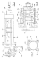
- Figure 1 is a side view of the entire cylinder-piston unit.
- Figure 2 is a section on the plane II-II of Figure 1.
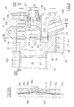
- Figure 3 is an enlarged detail of Figure 1 relating to the headpiece.
- Figure 3A shows the detail of Figure 3 but without the cover which covers the visible lateral face.
- Figure 4 is a view of the other lateral face of the headpiece.
- Figure 5 shows the detail of Figure 4 but without the cover which covers the visible lateral face.
- Figure 5 is a section on the central vertical plane V-V of Figure 6.
- Figure 6b is a section on the plane VI-VI of Figure 5.
- Figure 6A is an enlarged detail of Figure 6.
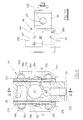
- Figure 7 is a section on the plane VII-VII of Figure 3.
- Figure 8 is a section on the plane VIII-VIII of Figure 5.
- Figure 9 is a partial section on the series of planes IX-IX of Figure 3.
- Figure 10 is a plan view from below of the headpiece shown without the pilot valve 40.
- the cylinder-piston unit shown in the figures comprises a cylindrical wall 10 and a piston 13 slidable in sealed contact with the inner surface of the wall 10, to move an axial rod 14.
- the two ends of the wall 10 are closed, at the rear by a headpiece 20 and at the front by a front closure element (endpiece) 15, through which the rod 14 sealedly passes.
- the cylindrical wall 10 laterally bounds two opposing operating chambers 11 and 12, separated from each other by the piston 13. When one of these chambers expands the other contracts with the piston moving in a certain direction, and vice versa.
- the cylindrical wall 10 is joined to the headpiece 10 and to the endpiece 15 by screws inserted in the direction of the axis of the cylinder-piston unit through holes 253 provided through the headpiece 20 and through holes (not shown) provided through the endpiece 15. These screws engage corresponding threaded holes 101 provided at both ends of the wall 10, in longitudinal protuberances 16 integral with the wall 10 and projecting radially from it.
- the headpiece 20 comprises a body 25, of substantially parallelepiped shape in the figures, having a projection extending about it to define a square-perimeter flange 252 through which said holes 253 are formed.
- the first conduit 21 and the second conduit 22 consist of dead holes which open into the front face of the headpiece body 25, they being positioned with their axes longitudinal and mutually superposed, and lying in the longitudinal vertical plane of symmetry.
- the inlet 23 comprises a cavity 231 of longitudinal axis, closed at both ends and positioned below said conduits 21 and 22.
- the cavity 231 lies with its axis in the vertical plane of symmetry, and communicates with the outside via an inclined lower conduit 232 which opens into the lower face 25' of the body 25.
- first passage A between the inlet 23 and the first conduit 21 provided in the body 25.
- This passage A has two spaced-apart ports 31a and 32a situated in the same right side face 26d of the body 25.
- the port 31a communicates with the inlet 23 via a short horizontal transverse channel 33a, the other port 32a communicating with the first conduit 21 via a short horizontal transverse channel 34a.
- each of said short channels 33a and 34a (and the analogous channels 33b, 33c, 33d, 34b, 34c, 34d described below) is composed of a pair of short channels, with their cross-section in the form of an elongate thin slot, separated by a thin wall.
- each of the ports 31a and 32a (and the analogous ports 31b, 31c, 31d, 32b, 32c, 32d described below) is composed of two elongate narrow ports separated by a thin strip.
- each said pair of channels 33, 34 and ports 31, 32 is indicated herein as a single channel or single port.
- a second passage B between the outlet 24 and the first conduit 21 provided within the body 25.
- This passage B has two spaced-apart ports 31b and 32b situated in the same right side face 26d of the body 25.
- the port 31b communicates with the first conduit 21 via a short horizontal transverse channel 33b, the other port 32b communicating with the outlet 24 via a short horizontal transverse channel 34b.
- a third passage C between the inlet 23 and the second conduit 22 provided within the body 25.
- This passage C has two spaced-apart ports 31c and 32c situated in the same left side face 26s of the body 25.
- the port 31c communicates with the inlet 23 via a short horizontal transverse channel 33c, the other port 32c communicating with the second conduit 22 via a short horizontal transverse channel 34c.
- a fourth passage D between the outlet 24 and the second conduit 22 provided within the body 25.
- This passage D has two spaced-apart ports 31d and 32d situated in the same left side face 26s of the body 25.
- the port 31d communicates with the second conduit 22 via a short horizontal transverse channel 33d, the other port 32d communicating with the outlet 24 via a short horizontal transverse channel 34d.
- each of said passages A, B, C, D there is provided a respective lateral chamber 35a, 35b, 35c, 35d (hereinafter indicated generically by 35) which covers the communication ports 31a, 31b, 31c, 31d and 32a, 32b, 32c, 32d (hereinafter indicated generically by 31 and 32 respectively).
- the lateral chamber 35 is provided in a cover positioned on the lateral face of the headpiece body.
- the chamber 35a of the first passage A and the chamber 35b of the second passage B are defined by respective recesses provided in the flat inner surface of one and the same cover 27d, which is adheringly fixed to the right face 26d of the body 25 to cover virtually the whole of this face.
- the chamber 35c of the third passage C and the chamber 35d of the fourth passage D are defined by respective recesses provided in the flat inner surface of another cover 27s, which is adheringly fixed to the left face 26s to cover virtually the whole of this face.
- a fluid passage opening and closure valve comprising a free flexible membrane 36a, 36b, 36c, 36d respectively, which separates the ports 31 and 32 of the lateral chamber 35.
- the membrane 36 has an area such as to cover said ports 31 and 32, and is arranged to assume a first position in which it lies adhering to the edge of the ports and a second position in which it is raised from the edge of the ports.
- the membrane 36a of the first passage A and the membrane 36b of the second passage B are formed from a single thin, flexible, deformable sheet 37d, which is pressed by the cover 27d against the face 26d, and has an area equal to that of the cover.
- the sheet 37d is free to flex and deform in correspondence with the lateral chambers 35a and 35b, to define the respective membrane 36.
- the membrane 36c of the third passage C and the membrane 36d of the fourth passage D are formed from a single thin, flexible, deformable sheet 37s, which is pressed by the cover 27s against the face 26s, and has an area equal to that of the cover 27s.
- the sheet 37s is free to flex and deform in correspondence with the lateral chambers 35c and 35d, to define the respective membrane 36.
- the two covers 27d and 27s are fixed to the body 25 by screws (not shown in the figures) which pass through holes 71 and 72 provided in the covers 27d and 27s and in the headpiece body 25 respectively.
- Figure 6A shows by way of example one of the passages A, B, C, D (specifically the first passage A).
- the two ports 31 and 32 (specifically 31a and 32a) lie in one and the same plane represented by the lateral face 26d, in this plane there lying the membrane 36 (36a) which covers the ports 31 and 32, separating them from the lateral chamber 35 (35a).
- a pilot fluid can be fed into the lateral chamber 35 at a pressure able to urge the membrane 36 into its first position, ie adhering to the edge of the ports 31 and/or 32 (as shown by dashed and dotted lines in Figure 6A and with full lines in Figures 6-9), in order to close these ports and hence prevent passage between the ports.
- the pilot fluid pressure must be such as to press on the membrane 36 with a force sufficient to prevent the force of the fluid present in the short channels 33 and 34, and hence in the ports 31 and 32, being able to separate the membrane 36 from the ports, ie sufficient to prevent passage through these ports.
- part of the feed fluid, withdrawn from the inlet 23, is used as the pilot fluid (as described hereinafter).
- This fluid, fed without relevant pressure drop, into the lateral chamber 35 has a pressure which is amply sufficient to maintain the membrane in its first position even against the feed pressure present in the inlet 23.
- the membrane 36 does not offer substantial resistance to fluid passage and lifts from the ports 31 and 32 (as shown by the full line in Figure 6A) to allow fluid to pass freely from one port 31 to the other port 32.
- the pilot fluid is distributed to the passages A, B, C, D by a pilot valve 40 positioned on the inner face 26' of the body 25.
- the valve 40 communicates with the fluid feed, in particular the inlet 23, and is arranged to distribute the pilot fluid to the lateral chambers 35 via the pilot channels on command.
- the valve 40 is an electrically operated distributor valve. It can be a valve of known type or of the type illustrated in Italian Patent Application No. RE99A000032 filed on 18 March 1999 by the present applicant.
- the cylindrical wall 10 comprises a longitudinally extending channel 222 provided within the thickness of the wall (see Figure 2) and connected at one end to the second conduit 22, its other end opening into the second operating chamber 12 of the cylinder-piston unit.
- first conduit 21 communicates directly with the first operating chamber 11 of the cylinder-piston unit.
- the conduit 21 possesses a front axial portion 21' communicating directly with the operating chamber 11 and a second axial portion 21" to the rear of the first, which communicates with the first via an axial passage hole 212, on which there acts a conical piece 213 coaxial to the hole 212 and positioned at a short (but adjustable) distance therefrom.
- the conical piece 213 defines together with the hole 212 a valve which reduces the pressure of the fluid in passing from the first portion 21' to the second portion 21".
- the channel 34a of the first passage A opens into the front portion 21', the channel 33d of the fourth passage D opening into the rear portion 21".
- a duct 51 which, by avoiding the various cavities provided within the body 25, leads both to the lateral chamber 35a of the first passage A, and to the lateral chamber 35d of the fourth passage D.
- a duct 52 which, by avoiding the various cavities provided within the body 25, leads both to the lateral chamber 35b of the second passage B, and to the lateral chamber 35c of the third passage C.
- the duct 51 comprises (see Figure 9 in particular):
- the duct 51 also comprises:
- the second duct 52 comprises:
- the duct 52 also comprises:
- the pilot valve 40 comprises a port 41 and a port 42 positioned in correspondence respectively with the port 51' and with the port 52' provided in the lower face 26' of the body 25.
- the valve 40 also comprises an inlet 43 which communicates with the inlet 23 via a channel 53 provided within the body 25 from its lower face 26'.
- the valve 40 comprises an outlet 44 which discharges to atmosphere via a channel 54 provided in the lower face 26' of the body 25.
- the first pilot duct 51 is connected to the discharge outlet 44, whereas the second duct 52 is connected to the inlet 23.
- the lateral chamber 35a of the first passage A and the lateral chamber 35d of the fourth passage D are put to discharge, the respective membranes 36 consequently allowing free passage of the operating fluid.
- the lateral chamber 35b of the second passage B and the lateral chamber 35c of the third passage C are put under pressure, the respective membranes 36 consequently being pressed against the respective ports 31 and 32 to close passage for the operating fluid.
- the operating fluid passes from the inlet 23 to the first conduit 21 and from there to the first operating chamber 11 of the cylinder-piston unit.
- the fluid present in the second operating chamber 12 of the cylinder-piston unit is connected to discharge 24 via the second conduit 22.
- the first pilot duct 51 is connected to the inlet 23, whereas the second duct 52 is connected to the discharge outlet 44.
- the lateral chamber 35a of the first passage A and the lateral chamber 35d of the fourth passage D are put under pressure, the respective membranes 36 consequently being pressed against the respective ports 31 and 32 to close the passage for the operating fluid.
- the lateral chamber 35b of the second passage B and the lateral chamber 35c of the third passage C are put to discharge with the result that the respective membranes 36 leave the passage for the operating fluid free.
- the operating fluid passes from the inlet 23 to the second conduit 22 via the third passage C, and from there to the second operating chamber 12 of the cylinder-piston unit. Simultaneously, the fluid present in the first operating chamber 11 of the cylinder-piston unit is connected via the first conduit 21 to discharge 24 via the second passage B.
- the headpiece 20 therefore comprises every means which, together with the valve 40, enables the cylinder-piston unit to be operated. It is necessary merely to connect the inlet 23 to a feed pipe for the pressurized operating fluid and connect the pilot valve 40 to an electrical supply cable.
- the cylinder-piston unit is single-acting, ie it possesses only one operating chamber, for example the chamber 11, which is connected alternately to the feed and discharge via the headpiece 20.
- the headpiece 20 possesses only the first conduit 21, plus the inlet 23 and discharge 24. It also possesses only the first passage A and the second passage B, together with a single cover 27d.
- the first pilot duct 51 hence communicates only with the chamber 35a, and the second pilot duct 52 communicates only with the chamber 35d of the second passage B.
- the pilot valve 40 remains unmodified.
- the first duct 51 is connected to the discharge outlet 44, whereas the second duct 52 is connected to the inlet 23.
- the lateral chamber 35a of the first passage A is put to discharge with the result that the respective membrane 36 leaves the passage for the operating fluid free.
- the lateral chamber 35b of the second passage B is put under pressure, the respective membrane 36 consequently being pressed against the ports 31 and 32 to close passage for the operating fluid.
- the operating fluid passes from the inlet 23 to the first conduit 21 and from there to the first operating chamber 11 of the cylinder-piston unit.
- the first duct 51 is connected to the inlet 23, whereas the second duct 52 is connected to the discharge outlet 44.
- the lateral chamber 35a of the first passage A is put under pressure, the respective membrane 36 consequently being pressed against the ports 31 and 32 to close the passage for the operating fluid.
- the lateral chamber 35b of the second passage B is put to discharge with the result that the respective membrane 36 leaves the passage for the operating fluid free.
- first chamber 11 of the cylinder-piston unit is connected to discharge 24 via the first conduit 21 and via the second passage B.
Landscapes
- Engineering & Computer Science (AREA)
- Physics & Mathematics (AREA)
- Fluid Mechanics (AREA)
- Mechanical Engineering (AREA)
- General Engineering & Computer Science (AREA)
- Actuator (AREA)
- Control Of Vending Devices And Auxiliary Devices For Vending Devices (AREA)
- Pens And Brushes (AREA)
- Diaphragms For Electromechanical Transducers (AREA)
Applications Claiming Priority (2)
| Application Number | Priority Date | Filing Date | Title |
|---|---|---|---|
| IT1999RE000118A IT1311049B1 (it) | 1999-11-17 | 1999-11-17 | Martinetto a fluido. |
| ITRE990118 | 1999-11-17 |
Publications (2)
| Publication Number | Publication Date |
|---|---|
| EP1101952A2 true EP1101952A2 (de) | 2001-05-23 |
| EP1101952A3 EP1101952A3 (de) | 2003-08-13 |
Family
ID=11399514
Family Applications (1)
| Application Number | Title | Priority Date | Filing Date |
|---|---|---|---|
| EP00203870A Withdrawn EP1101952A3 (de) | 1999-11-17 | 2000-11-06 | Druckmittelangetriebene Kolben-Zylindervorrichtung |
Country Status (2)
| Country | Link |
|---|---|
| EP (1) | EP1101952A3 (de) |
| IT (1) | IT1311049B1 (de) |
Cited By (2)
| Publication number | Priority date | Publication date | Assignee | Title |
|---|---|---|---|---|
| CN102367824A (zh) * | 2011-11-04 | 2012-03-07 | 武汉工程大学 | 气控阀式振动冲击装置 |
| CN103982487A (zh) * | 2014-05-29 | 2014-08-13 | 苏州大学张家港工业技术研究院 | 一种冲击气缸 |
Family Cites Families (5)
| Publication number | Priority date | Publication date | Assignee | Title |
|---|---|---|---|---|
| GB1370768A (en) * | 1973-03-28 | 1974-10-16 | Bosch Gmbh Robert | Cylinder and piston unit and control device therefor |
| JPS58124808A (ja) * | 1982-01-20 | 1983-07-25 | Mitsubishi Heavy Ind Ltd | 高速複動ピストン |
| JPS58134204A (ja) * | 1982-02-03 | 1983-08-10 | Mitsubishi Heavy Ind Ltd | 空気作動式往復駆動装置 |
| JPH10103309A (ja) * | 1996-09-25 | 1998-04-21 | Nec Yamagata Ltd | シリンダ |
| IT1311040B1 (it) * | 1999-03-18 | 2002-02-28 | Conductor Technology Ltd | Valvola per intercettare i fluidi, in particolare per fluidi a bassapressione. |
-
1999
- 1999-11-17 IT IT1999RE000118A patent/IT1311049B1/it active
-
2000
- 2000-11-06 EP EP00203870A patent/EP1101952A3/de not_active Withdrawn
Cited By (3)
| Publication number | Priority date | Publication date | Assignee | Title |
|---|---|---|---|---|
| CN102367824A (zh) * | 2011-11-04 | 2012-03-07 | 武汉工程大学 | 气控阀式振动冲击装置 |
| CN102367824B (zh) * | 2011-11-04 | 2013-07-10 | 武汉工程大学 | 气控阀式振动冲击装置 |
| CN103982487A (zh) * | 2014-05-29 | 2014-08-13 | 苏州大学张家港工业技术研究院 | 一种冲击气缸 |
Also Published As
| Publication number | Publication date |
|---|---|
| ITRE990118A1 (it) | 2001-05-17 |
| IT1311049B1 (it) | 2002-02-28 |
| ITRE990118A0 (it) | 1999-11-17 |
| EP1101952A3 (de) | 2003-08-13 |
Similar Documents
| Publication | Publication Date | Title |
|---|---|---|
| KR0182825B1 (ko) | 절환밸브 연결체 | |
| US5868157A (en) | Pilot transfer valve | |
| EP0703391A1 (de) | Schienenmontiertes Modulventil | |
| US8689833B2 (en) | Valve device | |
| US5983921A (en) | Directional-control-valve-connected body | |
| EP0719949B9 (de) | Einrichtung für Wegeventile | |
| KR102755604B1 (ko) | 회전 드라이브 장치 및 그것을 갖춘 로봇의 로봇암 | |
| CA2199795A1 (en) | Fluid Delivery Apparatus | |
| KR20140121468A (ko) | 모듈식 유체 제어 시스템 | |
| US5845679A (en) | Pilot selector valve | |
| EP0704648B1 (de) | Schaltventil | |
| US12540524B2 (en) | Piston actuated valve apparatus | |
| EP0703392A1 (de) | Dichtung für eine Ventileinheit | |
| CN110573751A (zh) | 电动气动的控制器以及配备有该控制器的过程控制装置 | |
| EP1101952A2 (de) | Druckmittelangetriebene Kolben-Zylindervorrichtung | |
| CA1053535A (en) | Modular selector valve assembly | |
| JP3524723B2 (ja) | 電気操作弁マニホールド | |
| US20030094095A1 (en) | Fluid-operated cylinder-piston unit | |
| KR102403885B1 (ko) | 밸브 장치 및 유체 제어 장치 | |
| US4465100A (en) | Four-way stacking valve with common electrical conduit and individual body mounted exhaust flow controls | |
| JPH01216174A (ja) | シャトル弁装置 | |
| JPH0364721B2 (de) | ||
| US20220049721A1 (en) | Switching unit and pneumatic system | |
| EP1141545B1 (de) | Pumpe | |
| JP2003322273A (ja) | インターロック用バルブ |
Legal Events
| Date | Code | Title | Description |
|---|---|---|---|
| PUAI | Public reference made under article 153(3) epc to a published international application that has entered the european phase |
Free format text: ORIGINAL CODE: 0009012 |
|
| AK | Designated contracting states |
Kind code of ref document: A2 Designated state(s): AT BE CH CY DE DK ES FI FR GB GR IE IT LI LU MC NL PT SE TR |
|
| AX | Request for extension of the european patent |
Free format text: AL;LT;LV;MK;RO;SI |
|
| PUAL | Search report despatched |
Free format text: ORIGINAL CODE: 0009013 |
|
| AK | Designated contracting states |
Designated state(s): AT BE CH CY DE DK ES FI FR GB GR IE IT LI LU MC NL PT SE TR |
|
| AX | Request for extension of the european patent |
Extension state: AL LT LV MK RO SI |
|
| AKX | Designation fees paid | ||
| REG | Reference to a national code |
Ref country code: DE Ref legal event code: 8566 |
|
| STAA | Information on the status of an ep patent application or granted ep patent |
Free format text: STATUS: THE APPLICATION IS DEEMED TO BE WITHDRAWN |
|
| 18D | Application deemed to be withdrawn |
Effective date: 20040214 |