EP1101947B1 - Rub resistant compressor stage - Google Patents
Rub resistant compressor stage Download PDFInfo
- Publication number
- EP1101947B1 EP1101947B1 EP20000307007 EP00307007A EP1101947B1 EP 1101947 B1 EP1101947 B1 EP 1101947B1 EP 20000307007 EP20000307007 EP 20000307007 EP 00307007 A EP00307007 A EP 00307007A EP 1101947 B1 EP1101947 B1 EP 1101947B1
- Authority
- EP
- European Patent Office
- Prior art keywords
- offset
- blade
- casing
- lands
- target
- Prior art date
- Legal status (The legal status is an assumption and is not a legal conclusion. Google has not performed a legal analysis and makes no representation as to the accuracy of the status listed.)
- Expired - Lifetime
Links
- 239000003570 air Substances 0.000 description 6
- 230000001965 increasing effect Effects 0.000 description 6
- 230000001052 transient effect Effects 0.000 description 6
- 238000000576 coating method Methods 0.000 description 5
- 239000007789 gas Substances 0.000 description 5
- 230000002411 adverse Effects 0.000 description 3
- 239000013536 elastomeric material Substances 0.000 description 3
- 239000002184 metal Substances 0.000 description 3
- 230000008901 benefit Effects 0.000 description 2
- 230000015556 catabolic process Effects 0.000 description 2
- 238000006731 degradation reaction Methods 0.000 description 2
- 238000006073 displacement reaction Methods 0.000 description 2
- 238000005299 abrasion Methods 0.000 description 1
- 239000012080 ambient air Substances 0.000 description 1
- 238000005452 bending Methods 0.000 description 1
- 239000000567 combustion gas Substances 0.000 description 1
- 230000006835 compression Effects 0.000 description 1
- 238000007906 compression Methods 0.000 description 1
- 238000010276 construction Methods 0.000 description 1
- 230000008602 contraction Effects 0.000 description 1
- 238000005336 cracking Methods 0.000 description 1
- 230000000694 effects Effects 0.000 description 1
- 230000002708 enhancing effect Effects 0.000 description 1
- 230000003628 erosive effect Effects 0.000 description 1
- 239000000446 fuel Substances 0.000 description 1
- 239000000463 material Substances 0.000 description 1
- 230000002028 premature Effects 0.000 description 1
- 230000009467 reduction Effects 0.000 description 1
- 239000007787 solid Substances 0.000 description 1
- 238000011144 upstream manufacturing Methods 0.000 description 1
Images


Classifications
-
- F—MECHANICAL ENGINEERING; LIGHTING; HEATING; WEAPONS; BLASTING
- F04—POSITIVE - DISPLACEMENT MACHINES FOR LIQUIDS; PUMPS FOR LIQUIDS OR ELASTIC FLUIDS
- F04D—NON-POSITIVE-DISPLACEMENT PUMPS
- F04D29/00—Details, component parts, or accessories
- F04D29/08—Sealings
- F04D29/16—Sealings between pressure and suction sides
- F04D29/161—Sealings between pressure and suction sides especially adapted for elastic fluid pumps
- F04D29/164—Sealings between pressure and suction sides especially adapted for elastic fluid pumps of an axial flow wheel
-
- F—MECHANICAL ENGINEERING; LIGHTING; HEATING; WEAPONS; BLASTING
- F01—MACHINES OR ENGINES IN GENERAL; ENGINE PLANTS IN GENERAL; STEAM ENGINES
- F01D—NON-POSITIVE DISPLACEMENT MACHINES OR ENGINES, e.g. STEAM TURBINES
- F01D11/00—Preventing or minimising internal leakage of working-fluid, e.g. between stages
- F01D11/08—Preventing or minimising internal leakage of working-fluid, e.g. between stages for sealing space between rotor blade tips and stator
-
- F—MECHANICAL ENGINEERING; LIGHTING; HEATING; WEAPONS; BLASTING
- F04—POSITIVE - DISPLACEMENT MACHINES FOR LIQUIDS; PUMPS FOR LIQUIDS OR ELASTIC FLUIDS
- F04D—NON-POSITIVE-DISPLACEMENT PUMPS
- F04D29/00—Details, component parts, or accessories
- F04D29/40—Casings; Connections of working fluid
- F04D29/52—Casings; Connections of working fluid for axial pumps
- F04D29/522—Casings; Connections of working fluid for axial pumps especially adapted for elastic fluid pumps
- F04D29/526—Details of the casing section radially opposing blade tips
-
- F—MECHANICAL ENGINEERING; LIGHTING; HEATING; WEAPONS; BLASTING
- F04—POSITIVE - DISPLACEMENT MACHINES FOR LIQUIDS; PUMPS FOR LIQUIDS OR ELASTIC FLUIDS
- F04D—NON-POSITIVE-DISPLACEMENT PUMPS
- F04D29/00—Details, component parts, or accessories
- F04D29/66—Combating cavitation, whirls, noise, vibration or the like; Balancing
- F04D29/68—Combating cavitation, whirls, noise, vibration or the like; Balancing by influencing boundary layers
- F04D29/681—Combating cavitation, whirls, noise, vibration or the like; Balancing by influencing boundary layers especially adapted for elastic fluid pumps
- F04D29/685—Inducing localised fluid recirculation in the stator-rotor interface
-
- F—MECHANICAL ENGINEERING; LIGHTING; HEATING; WEAPONS; BLASTING
- F05—INDEXING SCHEMES RELATING TO ENGINES OR PUMPS IN VARIOUS SUBCLASSES OF CLASSES F01-F04
- F05D—INDEXING SCHEME FOR ASPECTS RELATING TO NON-POSITIVE-DISPLACEMENT MACHINES OR ENGINES, GAS-TURBINES OR JET-PROPULSION PLANTS
- F05D2240/00—Components
- F05D2240/10—Stators
- F05D2240/11—Shroud seal segments
-
- Y—GENERAL TAGGING OF NEW TECHNOLOGICAL DEVELOPMENTS; GENERAL TAGGING OF CROSS-SECTIONAL TECHNOLOGIES SPANNING OVER SEVERAL SECTIONS OF THE IPC; TECHNICAL SUBJECTS COVERED BY FORMER USPC CROSS-REFERENCE ART COLLECTIONS [XRACs] AND DIGESTS
- Y10—TECHNICAL SUBJECTS COVERED BY FORMER USPC
- Y10S—TECHNICAL SUBJECTS COVERED BY FORMER USPC CROSS-REFERENCE ART COLLECTIONS [XRACs] AND DIGESTS
- Y10S415/00—Rotary kinetic fluid motors or pumps
- Y10S415/914—Device to control boundary layer
Definitions
- the present invention relates generally to gas turbine engines and more specifically, to compressors therein.
- Air is compressed in various fan and compressor stages by rotor blades cooperating with stator vanes.
- Fan air is used for providing propulsion thrust, and compressor air is mixed with fuel and ignited for generating hot combustion gases from which energy is extracted by turbine stages which power the compressor and fan.
- One conventional turbofan engine commercially used for many years includes a low temperature fan having a plurality of stall grooves disposed in the inner surface of the fan casing, see any of GB-A-2092681 or US-A-4767266.
- the stall grooves improve stall margin of the air as it is compressed during operation.
- the fan casing and its stall grooves are positioned radially close to the blade tips for minimizing the radial gap or clearance therebetween during operation.
- differential expansion or contraction, or other radial movement, between the stator casing and the rotor blades may cause temporary rubbing of the blade tips against the casing.
- Blade tip rubbing generates abrasion and friction heat and subjects the blade tips and casing to locally high stress. Repeated or extensive tip rubbing may lead to premature cracking in the blade tips which require suitable repair or replacement of the blades.
- Tip rubbing may be reduced or eliminated by increasing the nominal blade tip clearance, but this results in a corresponding decrease in engine efficiency.
- Abrasive coatings may be applied to the blade tips for minimizing degradation thereof due to rubbing with the stator casing.
- the abrasive coatings themselves are subject to wear and may be prematurely damaged upon rubbing the intervening lands between the stall grooves.
- the use of abrasive tip coatings may adversely affect the mechanical properties of the blade material itself limiting the useful life thereof.
- Abradable coatings may be added to the inside of the stator to minimize blade tip degradation during rubs.
- coatings soft enough to protect the blade tips are generally too soft to survive in an erosive environment and wear away leaving large tip clearances which adversely affect performance and stall margin of the engine.
- Fan or compressor blades are typically mounted to the perimeter of a rotor disk using conventional dovetails which permit the replacement of individual blades as desired. However, in a unitary or one-piece blisk the blades extend directly from their supporting disk and are not individually replaceable except by severing thereof from the disk.
- stall grooves are typically limited to low temperature fan applications so that they may be formed in an elastomeric material for preventing damage to blade tips during rubs therebetween.
- advanced gas turbine engines being developed operate at relatively higher temperature in fans and compressors which prevents the use of elastomeric material for stall grooves.
- the stall grooves must instead be formed in a high-strength metal which will significantly abrade blade tips during tip rubbing severely limiting the practical use thereof.
- a compressor casing is configured to surround blade tips in a compressor stage.
- the casing includes stall grooves with adjoining lands defining respective local gaps with the blade tips.
- the compressor stage comprises an offset between at least one of said lands (38a) and said blade tips to locally increase a corresponding one of said local gaps larger than said nominal gap for reducing tip rubbing at said offset as said tips rub said casing.
- FIG. 1 Illustrated in Figure 1 is an exemplary compressor stage 10 of a turbofan gas turbine engine in accordance with an exemplary embodiment of the present invention.
- the compressor stage is axisymmetrical about an axial centerline axis 12 and includes an annular rotor disk 14 which is powered by a turbine rotor (not shown).
- a plurality of rotor airfoils or blades 16 are circumferentially spaced apart around the perimeter of the disk 14 and extend radially outwardly therefrom in a unitary, one-piece blisk construction.
- the blade 16 may have conventional dovetails (not shown) removably mounted in corresponding dovetail slots formed in the perimeter of the disk in a conventional manner.
- Each blade 16 includes a generally concave, pressure side or sidewall 18. see also Figure 2. and a circumferentially opposite, generally convex suction side or sidewall 20. The two sides extend radially from a root 22 to a radially outer tip 24, and axially between a leading edge 26 and a trailing edge 28.
- the blade 16 is typically solid for fan or compressor applications, and has a plain, generally flat tip.
- stator vanes 30 which may be fixed or pivotable for controlling their performance.
- ambient air 32 flows axially downstream between the blades 16 for pressurization or compression thereof, and flows in turn through the stator vanes 30 through additional compressor or fan stages as desired for further increasing air pressure.
- the compressor stage illustrated in Figure 1 also includes a circumferentially arcuate casing 34 which may be formed in two semi-circular arcuate halves bolted together to form a complete ring.
- the casing 34 surrounds the blade tips and is spaced radially outwardly therefrom to define a nominal or primary tip clearance or gap A therebetween.
- the stator vanes 30 are suitably fixedly or pivotally mounted to the stator casing.
- the compressor casing 34 includes a plurality of circumferentially extending stall grooves 36 disposed in the radially inner surface of the casing and defined by corresponding ribs therebetween.
- the grooves 36 extend the full circumference of the casing 34, and are spaced axially apart by intervening or adjoining lands 38 to define respective local gaps with the blade tips 24.
- the lands 38 would be flat with sharp corners and spaced from the blade tip to effect the same nominal gap A at each land as at the casing inner surface bordering the stall grooves. In this way, the blade clearance may be controlled, and aerodynamic performance of the stall grooves may be maximized.
- conventional stall grooves are formed in an elastomeric material which prevents damage to the blade tips during tip rubbing.
- the casing 34 in which the stall grooves 36 are formed is not elastomeric, but instead is a suitable metal for the increased temperature requirements of the high performance compressor of which it is a part. Since the ribs defining the stall grooves and their lands 38 are now metal, an improved stall groove design is required for limiting damage from transient tip rubs during operation.
- At least one of the lands, designated 38a as shown in Figure 1 is radially offset relative to the blade tip to locally increase a corresponding one of the local or land gaps larger than the nominal gap A.
- each of the rotor blades illustrated generally in Figure 1, and more specifically in Figure 2 includes a fundamental natural vibratory frequency and corresponding mode shape, and higher order harmonics thereof.
- Each mode shape includes nodal lines of zero displacement, with increasing displacement therebetween with corresponding vibratory stress.
- the fundamental vibratory mode of a rotor blade is simple flexure bending of the blade from its root 22.
- the higher order harmonic modes of vibration result in correspondingly more complex mode shapes and correspondingly higher vibratory frequencies.
- Figure 2 illustrates a portion of an exemplary higher order vibratory mode shape having a local maximum vibratory stress at a portion of the blade tip 24 which defines a corresponding target 40.
- Conventional vibratory analysis may be used to identify the specific location of the locally high stress target 40 at the blade tip, which typically occurs in third, fourth, or higher modes of vibration typically referred to as stripe modes.
- the offset land 38a is selected for being axially aligned with the corresponding target 40 at the blade tip. In this way, rubbing of the blade tip against the casing and the non-offset lands 38 is limited to relatively low stress regions at the blade tip, whereas the high stress region at the target 40 is protected by the offset land 38a at which little or no rubbing occurs.
- the target 40 is disposed adjacent the blade leading edge 26 at the blade tip, and the offset land 38a is disposed radially thereabove in axial alignment therewith.
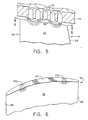
- Figure 3 illustrates an alternate embodiment of the casing 34 which also includes the offset land 38a adjacent the blade leading edge 26 radially atop the corresponding target 40. However, Figure 3 also illustrates a second offset land 38b which locally increases the gap above the blade tip 24 for being axially aligned radially above a second target 40b of local maximum vibratory stress adjacent the blade trailing edge 28.
- Figure 3 illustrates a common vibratory mode in which two local targets 40,40b of high vibratory stress are located along the blade tip between the leading and trailing edges.
- the first target 40 is generally at about 25% of the chord length, with the second target 40b being at about 75% of the chord length.
- the two offset lands 38a,b are therefore disposed at the opposite axial ends of the stall grooves 36 corresponding with the two targets 40,40b at opposite axial ends of the blade tips.
- stall grooves otherwise operate conventionally and may be configured for maximizing performance thereof notwithstanding the locally offset portions thereof.
- the blade tips 24 illustrated in Figures 1-3 are preferably flat and straight in axial section and axial projection, with the offset land 38a,b being preferably recessed in the casing by a suitable recess B.
- the recess B is relative to the inner surface of the casing and correspondingly increases the nominal gap A by the recess amount B at the individual offset lands 38a,b.
- the offset lands 38a,b are preferably flat or straight in axial section and have sharp upstream and downstream corners. In this way, all of the lands 38 may be flat with sharp corners for maximizing aerodynamic performance of the stall grooves during operation. And, in the event of transient blade rubbing with the casing 34. only those non-offset lands 38 will rub the blade tips at relatively low regions of stress, with the offset lands 38a,b being spaced from the selected high-stress regions of the blade tips at the targets.
- Figure 4 illustrates an alternate embodiment of the present invention wherein the offset lands, designated 38c, are arcuate in axial section and preferably have a constant radius such as being semi-circular at the radially inner ends of the dividing ribs of the stall grooves.
- the offset lands may be coextensive at their apexes with the adjoining lands, and offset in part as they curve radially outwardly.
- the nominal blade tip gap or clearance A is maintained at each of the lands, yet the arcuate offset lands will substantially reduce stress with the blade tips during a transient rub.
- the non-offset lands 38 maintain their sharp square-comers for enhancing aerodynamic performance, with the offset lands having radiused corners for reducing stress in compromise with maximum aerodynamic efficiency thereof.
- the offset lands, designated 38d are coextensive with the inner surface of the casing 34 and the adjoining non-offset lands 38.
- the otherwise flat blade tips 24 include respective targets, designated 40c, which are radially recessed inwardly into the blade tips at the desired locations of high vibratory stress thereat.
- the targets 40c are preferably axially arcuate and extend the full width of each blade between the pressure and suction sides.
- the recessed targets 40c cooperate with the corresponding offset lands 38d so that during blade rubbing with the casing 34, the offset lands 38d do not contact or rub with the recessed targets 40c.
- the depth of the recessed targets is limited to prevent rubbing with the corresponding lands while minimizing the local clearance therebetween for minimizing leakage of the compressed air over the blade tips.
- clearances between blade tips and the stator casing may be increased locally to prevent rubbing at critical locations on the blade tip. Since the increased clearances are local, their affect on aerodynamic performance will be minimal.
- the nominal blade tip clearance A may remain relatively small, and the configuration of the stall grooves 36 remains basically unchanged for maximizing performance thereof, while introducing relatively small local increase in clearance at selected lands. Blade tip rubbing at the offset lands is either eliminated or reduced, with corresponding reductions in stress concentration and stress during tip rubbing with the blades.
Landscapes
- Engineering & Computer Science (AREA)
- Mechanical Engineering (AREA)
- General Engineering & Computer Science (AREA)
- Structures Of Non-Positive Displacement Pumps (AREA)
- Other Air-Conditioning Systems (AREA)
- Separation Using Semi-Permeable Membranes (AREA)
- Inorganic Insulating Materials (AREA)
- Compressor (AREA)
Applications Claiming Priority (2)
| Application Number | Priority Date | Filing Date | Title |
|---|---|---|---|
| US09/439,436 US6234747B1 (en) | 1999-11-15 | 1999-11-15 | Rub resistant compressor stage |
| US439436 | 1999-11-15 |
Publications (3)
| Publication Number | Publication Date |
|---|---|
| EP1101947A2 EP1101947A2 (en) | 2001-05-23 |
| EP1101947A3 EP1101947A3 (en) | 2002-07-17 |
| EP1101947B1 true EP1101947B1 (en) | 2006-07-19 |
Family
ID=23744687
Family Applications (1)
| Application Number | Title | Priority Date | Filing Date |
|---|---|---|---|
| EP20000307007 Expired - Lifetime EP1101947B1 (en) | 1999-11-15 | 2000-08-16 | Rub resistant compressor stage |
Country Status (7)
| Country | Link |
|---|---|
| US (1) | US6234747B1 (enExample) |
| EP (1) | EP1101947B1 (enExample) |
| JP (1) | JP2001182694A (enExample) |
| AT (1) | ATE333591T1 (enExample) |
| DE (1) | DE60029405T2 (enExample) |
| ES (1) | ES2267465T3 (enExample) |
| IL (1) | IL137862A (enExample) |
Families Citing this family (39)
| Publication number | Priority date | Publication date | Assignee | Title |
|---|---|---|---|---|
| US6527509B2 (en) * | 1999-04-26 | 2003-03-04 | Hitachi, Ltd. | Turbo machines |
| US7213068B1 (en) * | 1999-11-12 | 2007-05-01 | Lucent Technologies Inc. | Policy management system |
| JP3862137B2 (ja) * | 2000-09-20 | 2006-12-27 | 淳一 黒川 | ターボ形水力機械 |
| JP3872966B2 (ja) * | 2001-06-29 | 2007-01-24 | 株式会社日立プラントテクノロジー | 軸流形流体機械 |
| DE10135003C1 (de) | 2001-07-18 | 2002-10-02 | Mtu Aero Engines Gmbh | Verdichtergehäusestruktur |
| AU2003207365A1 (en) * | 2002-02-28 | 2003-09-09 | Daimlerchrysler Ag | Anti-stall tip treatment means for turbo-compressors |
| GB0216952D0 (en) * | 2002-07-20 | 2002-08-28 | Rolls Royce Plc | Gas turbine engine casing and rotor blade arrangement |
| DE102004055439A1 (de) * | 2004-11-17 | 2006-05-24 | Rolls-Royce Deutschland Ltd & Co Kg | Strömungsarbeitsmaschine mit dynamischer Strömungsbeeinflussung |
| GB0513377D0 (en) * | 2005-06-30 | 2005-08-03 | Rolls Royce Plc | A blade |
| US7685823B2 (en) * | 2005-10-28 | 2010-03-30 | Power Systems Mfg., Llc | Airflow distribution to a low emissions combustor |
| GB0526011D0 (en) * | 2005-12-22 | 2006-02-01 | Rolls Royce Plc | Fan or compressor casing |
| GB0600532D0 (en) * | 2006-01-12 | 2006-02-22 | Rolls Royce Plc | A blade and rotor arrangement |
| GB2435904B (en) * | 2006-03-10 | 2008-08-27 | Rolls Royce Plc | Compressor Casing |
| US8172518B2 (en) * | 2006-12-29 | 2012-05-08 | General Electric Company | Methods and apparatus for fabricating a rotor assembly |
| DE102007037924A1 (de) * | 2007-08-10 | 2009-02-12 | Rolls-Royce Deutschland Ltd & Co Kg | Strömungsarbeitsmaschine mit Ringkanalwandausnehmung |
| DE102007053135A1 (de) * | 2007-11-08 | 2009-05-14 | Mtu Aero Engines Gmbh | Gasturbinenbauteil, insbesondere Flugtriebwerksbauteil bzw. Verdichterbauteil |
| US7988410B1 (en) | 2007-11-19 | 2011-08-02 | Florida Turbine Technologies, Inc. | Blade tip shroud with circular grooves |
| DE102008011644A1 (de) * | 2008-02-28 | 2009-09-03 | Rolls-Royce Deutschland Ltd & Co Kg | Gehäusestrukturierung für Axialverdichter im Nabenbereich |
| DE102008031982A1 (de) * | 2008-07-07 | 2010-01-14 | Rolls-Royce Deutschland Ltd & Co Kg | Strömungsarbeitsmaschine mit Nut an einem Laufspalt eines Schaufelendes |
| DE102008037154A1 (de) * | 2008-08-08 | 2010-02-11 | Rolls-Royce Deutschland Ltd & Co Kg | Strömungsarbeitsmaschine |
| US8177494B2 (en) * | 2009-03-15 | 2012-05-15 | United Technologies Corporation | Buried casing treatment strip for a gas turbine engine |
| US8602720B2 (en) | 2010-06-22 | 2013-12-10 | Honeywell International Inc. | Compressors with casing treatments in gas turbine engines |
| GB2487900B (en) | 2011-02-03 | 2013-02-06 | Rolls Royce Plc | A turbomachine comprising an annular casing and a bladed rotor |
| EP2530330B1 (de) * | 2011-06-01 | 2016-05-25 | MTU Aero Engines AG | Laufschaufel für einen Verdichter einer Turbomaschine, Verdichter sowie Turbomaschine |
| US20130089421A1 (en) * | 2011-10-05 | 2013-04-11 | Jeffrey Howard Nussbaum | Gas turbine engine airfoil tip recesses |
| US20140208756A1 (en) * | 2013-01-30 | 2014-07-31 | Alstom Technology Ltd. | System For Reducing Combustion Noise And Improving Cooling |
| EP2971547B1 (en) * | 2013-03-12 | 2020-01-01 | United Technologies Corporation | Cantilever stator with vortex initiation feature |
| EP2818724B1 (de) * | 2013-06-27 | 2020-09-23 | MTU Aero Engines GmbH | Strömungsmaschine und Verfahren |
| GB201410264D0 (en) | 2014-06-10 | 2014-07-23 | Rolls Royce Plc | An assembly |
| US10465716B2 (en) | 2014-08-08 | 2019-11-05 | Pratt & Whitney Canada Corp. | Compressor casing |
| US10066640B2 (en) * | 2015-02-10 | 2018-09-04 | United Technologies Corporation | Optimized circumferential groove casing treatment for axial compressors |
| US10107307B2 (en) * | 2015-04-14 | 2018-10-23 | Pratt & Whitney Canada Corp. | Gas turbine engine rotor casing treatment |
| CA2955646C (en) | 2016-01-19 | 2025-01-07 | Pratt & Whitney Canada Corp. | GAS TURBINE ROTOR BLADE HOUSING |
| CN105840551B (zh) * | 2016-04-15 | 2018-06-12 | 上海交通大学 | 多工况点高负荷压气机叶片的气动实现方法 |
| CN108506049A (zh) * | 2018-03-15 | 2018-09-07 | 哈尔滨工业大学 | 抑制涡轮顶部泄漏流动的球底棱柱凹腔叶顶 |
| US10995623B2 (en) | 2018-04-23 | 2021-05-04 | Rolls-Royce Corporation | Ceramic matrix composite turbine blade with abrasive tip |
| US11346232B2 (en) | 2018-04-23 | 2022-05-31 | Rolls-Royce Corporation | Turbine blade with abradable tip |
| CN109322709B (zh) * | 2018-09-13 | 2021-11-12 | 合肥通用机械研究院有限公司 | 一种透平膨胀机的可调式喷嘴叶片机构 |
| US20230151825A1 (en) * | 2021-11-17 | 2023-05-18 | Pratt & Whitney Canada Corp. | Compressor shroud with swept grooves |
Family Cites Families (12)
| Publication number | Priority date | Publication date | Assignee | Title |
|---|---|---|---|---|
| AT262333B (de) * | 1966-12-20 | 1968-06-10 | Elin Union Ag | Turbinenschaufelausbildung |
| GB1518293A (en) | 1975-09-25 | 1978-07-19 | Rolls Royce | Axial flow compressors particularly for gas turbine engines |
| US4239452A (en) * | 1978-06-26 | 1980-12-16 | United Technologies Corporation | Blade tip shroud for a compression stage of a gas turbine engine |
| JPS6318799Y2 (enExample) * | 1980-12-02 | 1988-05-26 | ||
| CA1158563A (en) * | 1981-01-27 | 1983-12-13 | Ulo Okapuu | Circumferentially grooved shroud liner |
| FR2558900B1 (fr) * | 1984-02-01 | 1988-05-27 | Snecma | Dispositif d'etancheite peripherique d'aubage de compresseur axial |
| GB2158879B (en) * | 1984-05-19 | 1987-09-03 | Rolls Royce | Preventing surge in an axial flow compressor |
| GB2245312B (en) | 1984-06-19 | 1992-03-25 | Rolls Royce Plc | Axial flow compressor surge margin improvement |
| RU2034175C1 (ru) * | 1993-03-11 | 1995-04-30 | Центральный институт авиационного моторостроения им.П.И.Баранова | Турбокомпрессор |
| JP3816150B2 (ja) * | 1995-07-18 | 2006-08-30 | 株式会社荏原製作所 | 遠心流体機械 |
| DE19619438B4 (de) * | 1996-05-14 | 2005-04-21 | Alstom | Wärmestausegment für eine Turbomaschine |
| US5997251A (en) * | 1997-11-17 | 1999-12-07 | General Electric Company | Ribbed turbine blade tip |
-
1999
- 1999-11-15 US US09/439,436 patent/US6234747B1/en not_active Expired - Fee Related
-
2000
- 2000-08-15 IL IL13786200A patent/IL137862A/xx not_active IP Right Cessation
- 2000-08-16 EP EP20000307007 patent/EP1101947B1/en not_active Expired - Lifetime
- 2000-08-16 ES ES00307007T patent/ES2267465T3/es not_active Expired - Lifetime
- 2000-08-16 DE DE2000629405 patent/DE60029405T2/de not_active Expired - Lifetime
- 2000-08-16 AT AT00307007T patent/ATE333591T1/de not_active IP Right Cessation
- 2000-08-18 JP JP2000248046A patent/JP2001182694A/ja not_active Ceased
Also Published As
| Publication number | Publication date |
|---|---|
| US6234747B1 (en) | 2001-05-22 |
| ES2267465T3 (es) | 2007-03-16 |
| IL137862A0 (en) | 2001-10-31 |
| IL137862A (en) | 2003-06-24 |
| EP1101947A2 (en) | 2001-05-23 |
| EP1101947A3 (en) | 2002-07-17 |
| JP2001182694A (ja) | 2001-07-06 |
| DE60029405T2 (de) | 2007-02-15 |
| ATE333591T1 (de) | 2006-08-15 |
| DE60029405D1 (de) | 2006-08-31 |
Similar Documents
| Publication | Publication Date | Title |
|---|---|---|
| EP1101947B1 (en) | Rub resistant compressor stage | |
| US6350102B1 (en) | Shroud leakage flow discouragers | |
| US8419356B2 (en) | Turbine seal assembly | |
| EP0792410B1 (en) | Rotor airfoils to control tip leakage flows | |
| EP1382799B1 (en) | Gas turbine engine casing and rotor blade arrangement | |
| CA2483391C (en) | Attachment of a ceramic shroud in a metal housing | |
| KR101338585B1 (ko) | 에어포일 및 압축기 및 고정자 조립체 | |
| CN102434220B (zh) | 可磨损动叶围带 | |
| US6027306A (en) | Turbine blade tip flow discouragers | |
| EP1505302B1 (en) | Compressor airfoil | |
| US7165937B2 (en) | Methods and apparatus for maintaining rotor assembly tip clearances | |
| US20120230818A1 (en) | Airfoil and corresponding guide vane, blade, gas turbine and turbomachine | |
| US9822647B2 (en) | High chord bucket with dual part span shrouds and curved dovetail | |
| US5791871A (en) | Turbine engine rotor assembly blade outer air seal | |
| EP1895108A2 (en) | Angel wing abradable seal and sealing method | |
| EP2309097A1 (en) | Airfoil and corresponding guide vane, blade, gas turbine and turbomachine | |
| JP2008163949A (ja) | ロータアセンブリを製造するための装置 | |
| US20190136700A1 (en) | Ceramic matrix composite tip shroud assembly for gas turbines | |
| US7549835B2 (en) | Leakage flow control and seal wear minimization system for a turbine engine | |
| EP3885533B1 (en) | Rotor blade for a turbomachine and corresponding turbomachine | |
| JP4677203B2 (ja) | ガスタービンエンジンのロータ組立体を設計するための方法及び装置 | |
| EP0922837B1 (en) | Fan case liner | |
| Bunker | Turbine blade tip flow discouragers |
Legal Events
| Date | Code | Title | Description |
|---|---|---|---|
| PUAI | Public reference made under article 153(3) epc to a published international application that has entered the european phase |
Free format text: ORIGINAL CODE: 0009012 |
|
| AK | Designated contracting states |
Kind code of ref document: A2 Designated state(s): AT BE CH CY DE DK ES FI FR GB GR IE IT LI LU MC NL PT SE |
|
| AX | Request for extension of the european patent |
Free format text: AL;LT;LV;MK;RO;SI |
|
| PUAL | Search report despatched |
Free format text: ORIGINAL CODE: 0009013 |
|
| AK | Designated contracting states |
Kind code of ref document: A3 Designated state(s): AT BE CH CY DE DK ES FI FR GB GR IE IT LI LU MC NL PT SE |
|
| AX | Request for extension of the european patent |
Free format text: AL;LT;LV;MK;RO;SI |
|
| RIC1 | Information provided on ipc code assigned before grant |
Free format text: 7F 04D 29/16 A, 7F 01D 11/08 B, 7F 04D 29/54 B, 7F 01D 11/12 B, 7F 01D 5/20 B |
|
| 17P | Request for examination filed |
Effective date: 20030117 |
|
| AKX | Designation fees paid |
Designated state(s): AT BE CH CY DE DK ES FI FR GB GR IE IT LI LU MC NL PT SE |
|
| 17Q | First examination report despatched |
Effective date: 20050517 |
|
| GRAP | Despatch of communication of intention to grant a patent |
Free format text: ORIGINAL CODE: EPIDOSNIGR1 |
|
| GRAS | Grant fee paid |
Free format text: ORIGINAL CODE: EPIDOSNIGR3 |
|
| GRAA | (expected) grant |
Free format text: ORIGINAL CODE: 0009210 |
|
| AK | Designated contracting states |
Kind code of ref document: B1 Designated state(s): AT BE CH CY DE DK ES FI FR GB GR IE IT LI LU MC NL PT SE |
|
| PG25 | Lapsed in a contracting state [announced via postgrant information from national office to epo] |
Ref country code: FI Free format text: LAPSE BECAUSE OF FAILURE TO SUBMIT A TRANSLATION OF THE DESCRIPTION OR TO PAY THE FEE WITHIN THE PRESCRIBED TIME-LIMIT Effective date: 20060719 Ref country code: BE Free format text: LAPSE BECAUSE OF FAILURE TO SUBMIT A TRANSLATION OF THE DESCRIPTION OR TO PAY THE FEE WITHIN THE PRESCRIBED TIME-LIMIT Effective date: 20060719 Ref country code: LI Free format text: LAPSE BECAUSE OF FAILURE TO SUBMIT A TRANSLATION OF THE DESCRIPTION OR TO PAY THE FEE WITHIN THE PRESCRIBED TIME-LIMIT Effective date: 20060719 Ref country code: NL Free format text: LAPSE BECAUSE OF FAILURE TO SUBMIT A TRANSLATION OF THE DESCRIPTION OR TO PAY THE FEE WITHIN THE PRESCRIBED TIME-LIMIT Effective date: 20060719 Ref country code: AT Free format text: LAPSE BECAUSE OF FAILURE TO SUBMIT A TRANSLATION OF THE DESCRIPTION OR TO PAY THE FEE WITHIN THE PRESCRIBED TIME-LIMIT Effective date: 20060719 Ref country code: CH Free format text: LAPSE BECAUSE OF FAILURE TO SUBMIT A TRANSLATION OF THE DESCRIPTION OR TO PAY THE FEE WITHIN THE PRESCRIBED TIME-LIMIT Effective date: 20060719 |
|
| REG | Reference to a national code |
Ref country code: GB Ref legal event code: FG4D |
|
| REG | Reference to a national code |
Ref country code: CH Ref legal event code: EP |
|
| PG25 | Lapsed in a contracting state [announced via postgrant information from national office to epo] |
Ref country code: IE Free format text: LAPSE BECAUSE OF NON-PAYMENT OF DUE FEES Effective date: 20060816 |
|
| REG | Reference to a national code |
Ref country code: IE Ref legal event code: FG4D |
|
| PG25 | Lapsed in a contracting state [announced via postgrant information from national office to epo] |
Ref country code: MC Free format text: LAPSE BECAUSE OF NON-PAYMENT OF DUE FEES Effective date: 20060831 |
|
| REF | Corresponds to: |
Ref document number: 60029405 Country of ref document: DE Date of ref document: 20060831 Kind code of ref document: P |
|
| REG | Reference to a national code |
Ref country code: SE Ref legal event code: TRGR |
|
| PG25 | Lapsed in a contracting state [announced via postgrant information from national office to epo] |
Ref country code: DK Free format text: LAPSE BECAUSE OF FAILURE TO SUBMIT A TRANSLATION OF THE DESCRIPTION OR TO PAY THE FEE WITHIN THE PRESCRIBED TIME-LIMIT Effective date: 20061019 |
|
| PG25 | Lapsed in a contracting state [announced via postgrant information from national office to epo] |
Ref country code: PT Free format text: LAPSE BECAUSE OF FAILURE TO SUBMIT A TRANSLATION OF THE DESCRIPTION OR TO PAY THE FEE WITHIN THE PRESCRIBED TIME-LIMIT Effective date: 20061219 |
|
| NLV1 | Nl: lapsed or annulled due to failure to fulfill the requirements of art. 29p and 29m of the patents act | ||
| ET | Fr: translation filed | ||
| REG | Reference to a national code |
Ref country code: ES Ref legal event code: FG2A Ref document number: 2267465 Country of ref document: ES Kind code of ref document: T3 |
|
| PLBE | No opposition filed within time limit |
Free format text: ORIGINAL CODE: 0009261 |
|
| STAA | Information on the status of an ep patent application or granted ep patent |
Free format text: STATUS: NO OPPOSITION FILED WITHIN TIME LIMIT |
|
| 26N | No opposition filed |
Effective date: 20070420 |
|
| PGFP | Annual fee paid to national office [announced via postgrant information from national office to epo] |
Ref country code: SE Payment date: 20060829 Year of fee payment: 7 |
|
| EUG | Se: european patent has lapsed | ||
| PG25 | Lapsed in a contracting state [announced via postgrant information from national office to epo] |
Ref country code: SE Free format text: LAPSE BECAUSE OF NON-PAYMENT OF DUE FEES Effective date: 20070817 Ref country code: GR Free format text: LAPSE BECAUSE OF FAILURE TO SUBMIT A TRANSLATION OF THE DESCRIPTION OR TO PAY THE FEE WITHIN THE PRESCRIBED TIME-LIMIT Effective date: 20061020 |
|
| PG25 | Lapsed in a contracting state [announced via postgrant information from national office to epo] |
Ref country code: LU Free format text: LAPSE BECAUSE OF NON-PAYMENT OF DUE FEES Effective date: 20060816 |
|
| REG | Reference to a national code |
Ref country code: ES Ref legal event code: FD2A Effective date: 20070817 |
|
| PG25 | Lapsed in a contracting state [announced via postgrant information from national office to epo] |
Ref country code: CY Free format text: LAPSE BECAUSE OF FAILURE TO SUBMIT A TRANSLATION OF THE DESCRIPTION OR TO PAY THE FEE WITHIN THE PRESCRIBED TIME-LIMIT Effective date: 20060719 |
|
| PG25 | Lapsed in a contracting state [announced via postgrant information from national office to epo] |
Ref country code: ES Free format text: LAPSE BECAUSE OF NON-PAYMENT OF DUE FEES Effective date: 20070817 |
|
| PGFP | Annual fee paid to national office [announced via postgrant information from national office to epo] |
Ref country code: FR Payment date: 20100903 Year of fee payment: 11 Ref country code: DE Payment date: 20100827 Year of fee payment: 11 Ref country code: IT Payment date: 20100825 Year of fee payment: 11 |
|
| PGFP | Annual fee paid to national office [announced via postgrant information from national office to epo] |
Ref country code: GB Payment date: 20100825 Year of fee payment: 11 |
|
| GBPC | Gb: european patent ceased through non-payment of renewal fee |
Effective date: 20110816 |
|
| REG | Reference to a national code |
Ref country code: FR Ref legal event code: ST Effective date: 20120430 |
|
| PG25 | Lapsed in a contracting state [announced via postgrant information from national office to epo] |
Ref country code: IT Free format text: LAPSE BECAUSE OF NON-PAYMENT OF DUE FEES Effective date: 20110816 |
|
| REG | Reference to a national code |
Ref country code: DE Ref legal event code: R119 Ref document number: 60029405 Country of ref document: DE Effective date: 20120301 |
|
| PG25 | Lapsed in a contracting state [announced via postgrant information from national office to epo] |
Ref country code: GB Free format text: LAPSE BECAUSE OF NON-PAYMENT OF DUE FEES Effective date: 20110816 Ref country code: FR Free format text: LAPSE BECAUSE OF NON-PAYMENT OF DUE FEES Effective date: 20110831 |
|
| PG25 | Lapsed in a contracting state [announced via postgrant information from national office to epo] |
Ref country code: DE Free format text: LAPSE BECAUSE OF NON-PAYMENT OF DUE FEES Effective date: 20120301 |