EP1101507B1 - Guide wire - Google Patents
Guide wire Download PDFInfo
- Publication number
- EP1101507B1 EP1101507B1 EP00124394A EP00124394A EP1101507B1 EP 1101507 B1 EP1101507 B1 EP 1101507B1 EP 00124394 A EP00124394 A EP 00124394A EP 00124394 A EP00124394 A EP 00124394A EP 1101507 B1 EP1101507 B1 EP 1101507B1
- Authority
- EP
- European Patent Office
- Prior art keywords
- wire
- distal end
- core
- body portion
- slender
- Prior art date
- Legal status (The legal status is an assumption and is not a legal conclusion. Google has not performed a legal analysis and makes no representation as to the accuracy of the status listed.)
- Expired - Lifetime
Links
- 229920005989 resin Polymers 0.000 claims description 22
- 239000011347 resin Substances 0.000 claims description 22
- 229910045601 alloy Inorganic materials 0.000 description 10
- 239000000956 alloy Substances 0.000 description 10
- 210000004204 blood vessel Anatomy 0.000 description 8
- -1 i.e. Inorganic materials 0.000 description 5
- 238000000034 method Methods 0.000 description 5
- 238000004519 manufacturing process Methods 0.000 description 4
- 238000003466 welding Methods 0.000 description 4
- 238000002583 angiography Methods 0.000 description 3
- 229910000531 Co alloy Inorganic materials 0.000 description 2
- XEEYBQQBJWHFJM-UHFFFAOYSA-N Iron Chemical compound [Fe] XEEYBQQBJWHFJM-UHFFFAOYSA-N 0.000 description 2
- PXHVJJICTQNCMI-UHFFFAOYSA-N Nickel Chemical compound [Ni] PXHVJJICTQNCMI-UHFFFAOYSA-N 0.000 description 2
- UXZUCXCKBOYJDF-UHFFFAOYSA-N [Ti].[Co].[Ni] Chemical compound [Ti].[Co].[Ni] UXZUCXCKBOYJDF-UHFFFAOYSA-N 0.000 description 2
- 229910017052 cobalt Inorganic materials 0.000 description 2
- 239000010941 cobalt Substances 0.000 description 2
- GUTLYIVDDKVIGB-UHFFFAOYSA-N cobalt atom Chemical compound [Co] GUTLYIVDDKVIGB-UHFFFAOYSA-N 0.000 description 2
- 239000000463 material Substances 0.000 description 2
- 239000010935 stainless steel Substances 0.000 description 2
- 229910001220 stainless steel Inorganic materials 0.000 description 2
- 229910000838 Al alloy Inorganic materials 0.000 description 1
- VYZAMTAEIAYCRO-UHFFFAOYSA-N Chromium Chemical compound [Cr] VYZAMTAEIAYCRO-UHFFFAOYSA-N 0.000 description 1
- 229910000640 Fe alloy Inorganic materials 0.000 description 1
- 229910000914 Mn alloy Inorganic materials 0.000 description 1
- 229910001182 Mo alloy Inorganic materials 0.000 description 1
- 229910001257 Nb alloy Inorganic materials 0.000 description 1
- 229910000990 Ni alloy Inorganic materials 0.000 description 1
- 239000004952 Polyamide Substances 0.000 description 1
- 239000005062 Polybutadiene Substances 0.000 description 1
- 239000004698 Polyethylene Substances 0.000 description 1
- XUIMIQQOPSSXEZ-UHFFFAOYSA-N Silicon Chemical compound [Si] XUIMIQQOPSSXEZ-UHFFFAOYSA-N 0.000 description 1
- 229910001297 Zn alloy Inorganic materials 0.000 description 1
- VZUPOJJVIYVMIT-UHFFFAOYSA-N [Mo].[Ni].[Cr].[Fe] Chemical compound [Mo].[Ni].[Cr].[Fe] VZUPOJJVIYVMIT-UHFFFAOYSA-N 0.000 description 1
- LMBUSUIQBONXAS-UHFFFAOYSA-N [Ti].[Fe].[Ni] Chemical compound [Ti].[Fe].[Ni] LMBUSUIQBONXAS-UHFFFAOYSA-N 0.000 description 1
- HZEWFHLRYVTOIW-UHFFFAOYSA-N [Ti].[Ni] Chemical compound [Ti].[Ni] HZEWFHLRYVTOIW-UHFFFAOYSA-N 0.000 description 1
- XAGFODPZIPBFFR-UHFFFAOYSA-N aluminium Chemical compound [Al] XAGFODPZIPBFFR-UHFFFAOYSA-N 0.000 description 1
- 229910052782 aluminium Inorganic materials 0.000 description 1
- 229910052790 beryllium Inorganic materials 0.000 description 1
- ATBAMAFKBVZNFJ-UHFFFAOYSA-N beryllium atom Chemical compound [Be] ATBAMAFKBVZNFJ-UHFFFAOYSA-N 0.000 description 1
- 229910052804 chromium Inorganic materials 0.000 description 1
- 239000011651 chromium Substances 0.000 description 1
- 239000011248 coating agent Substances 0.000 description 1
- 239000011247 coating layer Substances 0.000 description 1
- 238000000576 coating method Methods 0.000 description 1
- 150000001879 copper Chemical class 0.000 description 1
- TVZPLCNGKSPOJA-UHFFFAOYSA-N copper zinc Chemical compound [Cu].[Zn] TVZPLCNGKSPOJA-UHFFFAOYSA-N 0.000 description 1
- 238000007887 coronary angioplasty Methods 0.000 description 1
- 238000005520 cutting process Methods 0.000 description 1
- 230000001419 dependent effect Effects 0.000 description 1
- 238000007598 dipping method Methods 0.000 description 1
- 230000002526 effect on cardiovascular system Effects 0.000 description 1
- 239000008151 electrolyte solution Substances 0.000 description 1
- 239000005038 ethylene vinyl acetate Substances 0.000 description 1
- 229920002313 fluoropolymer Polymers 0.000 description 1
- 150000002505 iron Chemical class 0.000 description 1
- 229910052742 iron Inorganic materials 0.000 description 1
- DALUDRGQOYMVLD-UHFFFAOYSA-N iron manganese Chemical compound [Mn].[Fe] DALUDRGQOYMVLD-UHFFFAOYSA-N 0.000 description 1
- 239000010410 layer Substances 0.000 description 1
- 230000003902 lesion Effects 0.000 description 1
- WPBNNNQJVZRUHP-UHFFFAOYSA-L manganese(2+);methyl n-[[2-(methoxycarbonylcarbamothioylamino)phenyl]carbamothioyl]carbamate;n-[2-(sulfidocarbothioylamino)ethyl]carbamodithioate Chemical compound [Mn+2].[S-]C(=S)NCCNC([S-])=S.COC(=O)NC(=S)NC1=CC=CC=C1NC(=S)NC(=O)OC WPBNNNQJVZRUHP-UHFFFAOYSA-L 0.000 description 1
- 150000002815 nickel Chemical class 0.000 description 1
- 229910052759 nickel Inorganic materials 0.000 description 1
- 229910001000 nickel titanium Inorganic materials 0.000 description 1
- 229920001200 poly(ethylene-vinyl acetate) Polymers 0.000 description 1
- 229920002647 polyamide Polymers 0.000 description 1
- 229920002857 polybutadiene Polymers 0.000 description 1
- 229920000573 polyethylene Polymers 0.000 description 1
- 229920001296 polysiloxane Polymers 0.000 description 1
- 229920002635 polyurethane Polymers 0.000 description 1
- 239000004814 polyurethane Substances 0.000 description 1
- 229920000915 polyvinyl chloride Polymers 0.000 description 1
- 239000004800 polyvinyl chloride Substances 0.000 description 1
- 229910052710 silicon Inorganic materials 0.000 description 1
- 239000010703 silicon Substances 0.000 description 1
- 239000000243 solution Substances 0.000 description 1
- 229920003002 synthetic resin Polymers 0.000 description 1
- 239000000057 synthetic resin Substances 0.000 description 1
- 229910052715 tantalum Inorganic materials 0.000 description 1
- GUVRBAGPIYLISA-UHFFFAOYSA-N tantalum atom Chemical compound [Ta] GUVRBAGPIYLISA-UHFFFAOYSA-N 0.000 description 1
- BFKJFAAPBSQJPD-UHFFFAOYSA-N tetrafluoroethene Chemical group FC(F)=C(F)F BFKJFAAPBSQJPD-UHFFFAOYSA-N 0.000 description 1
- 229920002725 thermoplastic elastomer Polymers 0.000 description 1
- 150000003608 titanium Chemical class 0.000 description 1
- WFKWXMTUELFFGS-UHFFFAOYSA-N tungsten Chemical compound [W] WFKWXMTUELFFGS-UHFFFAOYSA-N 0.000 description 1
- 229910052721 tungsten Inorganic materials 0.000 description 1
- 239000010937 tungsten Substances 0.000 description 1
- 230000024883 vasodilation Effects 0.000 description 1
Images


Classifications
-
- A—HUMAN NECESSITIES
- A61—MEDICAL OR VETERINARY SCIENCE; HYGIENE
- A61M—DEVICES FOR INTRODUCING MEDIA INTO, OR ONTO, THE BODY; DEVICES FOR TRANSDUCING BODY MEDIA OR FOR TAKING MEDIA FROM THE BODY; DEVICES FOR PRODUCING OR ENDING SLEEP OR STUPOR
- A61M25/00—Catheters; Hollow probes
- A61M25/01—Introducing, guiding, advancing, emplacing or holding catheters
- A61M25/09—Guide wires
- A61M2025/09058—Basic structures of guide wires
- A61M2025/09075—Basic structures of guide wires having a core without a coil possibly combined with a sheath
-
- A—HUMAN NECESSITIES
- A61—MEDICAL OR VETERINARY SCIENCE; HYGIENE
- A61M—DEVICES FOR INTRODUCING MEDIA INTO, OR ONTO, THE BODY; DEVICES FOR TRANSDUCING BODY MEDIA OR FOR TAKING MEDIA FROM THE BODY; DEVICES FOR PRODUCING OR ENDING SLEEP OR STUPOR
- A61M25/00—Catheters; Hollow probes
- A61M25/01—Introducing, guiding, advancing, emplacing or holding catheters
- A61M25/09—Guide wires
- A61M2025/09175—Guide wires having specific characteristics at the distal tip
Definitions
- the present invention relates to a guide wire having a flexible distal end and for introducing a catheter to a desired part in a blood vessel of a human body for treatment or examination, such as angiography, a blood vessel occlusion technique, a vasodilation technique or the like.
- a guide wire is used to introduce a catheter into a lesion site at which a conventional surgical operation is difficult to carry out, for example, percutaneous transluminal coronary angioplasty (PTCA), cardiovascular angiography, a blood vessel closing operation or the like.
- PTCA percutaneous transluminal coronary angioplasty
- cardiovascular angiography a blood vessel closing operation or the like.
- Blood vessels have complicated curvatures and a guide wire is introduced to a desired part through the curved blood vessels. Therefore, a pertinent flexibility is required for a distal end of a guide wire in order to prevent damage to blood vessels with which the introduced guide wire is brought into contact.
- a guide wire usually comprises a core wire made of stainless steel or the like.
- a so called resin coated guide wire in which a distal section of the core wire is coated with a synthetic resin such as tetrafluoroethylene to provide smoothness to an outside of the core.
- the distal section of the core wire is tapered to thereby provide flexibility in order to facilitate in selecting a blood vessel in which the wire is to be inserted or in reaching a desired part and preventing damage to the blood vessel.
- Such tapering processing can be carried out by subjecting a straight core wire to a grinder referred to as a centerless grinder or by dipping a portion of a core wire to be a distal section in an electrolyte solution and pulling up the portion successively and slowly from the solution.
- the core wire can be coated with a resin by a resin extruder.
- one tapered short core wire must be separately coated with a resin. Accordingly, a distal end of the tapered short core wire is conventionally welded to a proximal end of another tapered short core wire by a laser or an arc welder to become a certain length of wire.
- the connected wire is coated with a resin continuously and cut at the most slender part of the connected wire into relatively short pieces, that becomes a core wire having both distal and proximal ends. Then there is carried out a so called rounding process in which the cut and exposed cross section of the both distal end and proximal ends of the core wire are coated with a resin.
- the present invention has been carried out in view of the above-described situation and it is an object thereof to provide a guide wire having a flexible distal end portion, and an uniform outer diameter along the entire length of the core without a stepped surface.
- a distal end portion of a core wire can be constituted by a plurality of slender wire filaments, a cross sectional area of the distal end portion of the core wire can be made smaller than a cross sectional area of a proximal portion thereof, and flexibility can be provided to the distal end portion of the core wire and completed the present invention.
- the cross sectional area means the area occupied by the entire wire filaments.
- the present invention relates to a guide wire having a flexible distal end and comprising a core wire 1 which comprises a core body portion 11 relatively larger in cross section and a distal end portion 12 which is relatively smaller in cross section provided on the distal end of the core body portion 11, and a resin envelope 2 covering on the core wire 1, wherein at least said distal end portion 12 comprises a sparse bundle of a plurality of slender wire filaments, and the core wire 1 has substantially no stepped difference between the core body portion 11 and the distal end portion 12.
- the core wire 1 comprises a core body portion 11 and a distal end portion 12, and may be constructed such that the distal end portion 12 thereof is provided at an end face of the distal end side of the core body portion 11 such that an outer periphery of the core body portion 11 coincides with an outer periphery of the distal end portion 12.
- the core wire 1 may be constructed such that the core wire 1 comprises a plurality of relatively long slender wire filaments in an outer portion of the core wire 1 and a plurality of relatively short slender wire filaments in an inner portion of the core wire 1, and the proximal end of the core wire 1 are bundled and fixed to coincide with each other.
- the sparse bundle of the slender wire filaments refers to an assembly of a plurality of slender wire filaments having clearances among contiguous ones of the slender wire filaments.
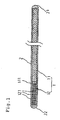
- Fig.1 is a longitudinal sectional view showing an embodiment of the present invention
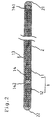
- Fig.2 is a longitudinal sectional view showing another embodiment of the present invention.
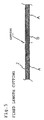
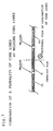
- Fig.3 to Fig.6 are explanatory views of fabrication steps of a guide wire as shown in Fig.1
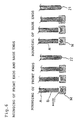
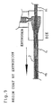
- Fig.7 to Fig.11 are explanatory views of fabrication steps of a guide wire as shown in Fig.2.
- a guide wire according to the present invention includes a core wire 1 having a core body portion 11 having a relatively large sectional area and a distal end portion 12 provided at a distal end 111 of the core body portion 11 and having a relatively small sectional area, at least the distal end portion 12 comprising a sparse bundle of a plurality of slender wire filaments 121 and having substantially no stepped difference (surface) between the distal end portion 12 and the core body portion 11, and a resin layer 2 coated on the core wire 1.
- the core wire 1 comprises core body portion 11 and distal end portion 12 provided at distal end 111 of the core body portion 11.
- Distal end portion 12 comprises a sparse bundle of a plurality of slender wire filaments 121 provided at an end face of the distal end 111 of the core body portion 11 such that an outer periphery of the distal end portion 12 coincides with an outer periphery of the end face.
- the core body portion 11 is a slender wire filament, a cross section of which is formed in a circular shape.
- a diameter (average) of the core body portion 11 is generally about 0.05 mm to 0.1 mm.
- the distal end portion 12 may be constructed such that the plurality of slender wire filaments 121 is previously formed adjacent to the distal end side of the core body portion 11, the distal end portion 12 may be constructed such that the plurality of slender wire filaments 121 is connected with the distal end 111 of the core body portion 11 by welding or the like.
- the diameter of each of the slender wire filaments 121 may be less than half of the diameter of the core body portion 11, a diameter of about a quarter to one eighth thereof is preferable.
- a guide wire shown by Fig.2 comprises a core wire 1 which comprises a plurality of relatively long slender wire filaments 13 existing in an outer portion of the core wire 1 and in both the core body portion 11 and distal end portion 12 and a plurality of relatively short slender wire filaments 14 existing in an inner portion of the core wire 1 and in core body portion 11.
- a number of the slender wire filaments in the distal end portion 12 is less than that of the core body portion 11.
- the slender wire filaments 13 and 14 of the core body portion 11 are bundled and fixed such that proximal sides thereof coincide with each other.
- the distal end portion of the relatively long slender wire filaments 13, that is, portions thereof projected to the outside of, or beyond, the relatively short slender wire filaments 14 constitute the flexible distal end portion 12 after being coated with a resin.
- diameters of the slender wire filaments 13 and 14 may be less than a half of the diameter of the core wire 1, about a quarter to one eighth is preferable.
- the slender wire filaments 13 and 14 can be fixed by welding at least portions of the slender wire filaments 14 including proximal end 141 and distal ends 142 at certain intervals by spot welding (see, Fig.8).
- the guide wire of this type it is efficient to weld the slender wire filaments at certain intervals by spot welding (see, Fig.7), reduce a number of the slender wire filaments, for instance, by a cutter in a certain zone (see, Fig.7 and 8, "n” part), coat the surface of the core wire 1 with a resin (see, Fig.9), cut the reduced part separately (see, Fig.10, "n” part) and round the distal end to thereby form the distal end portion 12 (see Fig.11).
- Super-elastic alloys include nickel series alloys, i.e., nickel-titanium alloys, nickel-titanium-cobalt alloys, nickel-titanium-iron alloys, nickel-aluminum-alloys, nickel-titanium-cobalt alloys; copper series alloys, i.e., copper-aluminum-nickel alloys, copper-zinc alloys, copper-zinc-X alloys (where X: beryllium, silicon, aluminum, or cobalt); titanium series of titanium-palladium-X alloys (where X: chromium, manganese, nickel, iron, cobalt, tungsten, or tantalum), iron series alloys, i.e., iron-manganese alloys and the like.
- High rigidity i.e., nickel-titanium alloys, nickel-titanium-cobalt alloys, nickel-titanium-iron alloys, nickel-aluminum-allo
- a coating material of the core wire there can be adopted polyurethane, polyamide, fluoroplastics including polytetrafluoroethylene, ethylene-tetrafluoroethylene copolymer or the like, polyvinyl chloride, ethylene-vinyl acetate copolymer, silicone, polybutadiene, polyethylene, thermoplastic elastomer and the like.
- the thickness of the coating layer depends on intended use, but generally, is about 0.05 mm to 0.5 mm.
- the diameter of the core wire 1 may be commonly about 0.03 mm to 1.0 mm and, preferably, about 0.05 mm to 0.1 mm for PTCA, or about 0.3 mm to 0.8 mm for angiography.
- the length of the distal end portion 12, the core body portion 11 and the core wire 1 may be selected in accordance with intended use. Usually, the length of the distal end portion 12 is less than that of the core body portion 11.
- a relatively thick slender wire filament A (diameter of 0.45 mm) constituting the core body portion 11 and a sparse bundle B of a plurality of relatively slender wire filaments (diameter of 0.1 mm, five pieces) constituting the distal end portion 12, are fixedly adhered to each other such that an outer periphery of B and an outer periphery of A coincide with each other to thereby form a wire filament member in which A and B are aligned alternately in the order A, B, A, B.
- the wire filament member is subjected to a resin extruder, coated with resin (see, Fig.4) and cut at a center part of A (not shown) and B as illustrated by Fig.5.
- the cut wire filament member coated with a resin is subjected to a die M to round the ends of the wire filament member, to thereby form a distal end 22 (see, Fig. 6, left) and a proximal 21 (see, Fig. 6, right) of the guide wire.
- the resin is positioned and melted in a cavity of the die M, and the cut wire filament member of the sparse bundle B is inserted in the cavity and pulled out from the die M to form the rounded distal end 22 of the distal end portion 12.
- the resin is also positioned and melted in a cavity of the die M, and the cut wire filament member of the thick slender wire filament is inserted in the cave and pulled out from the die M to form the rounded proximal 21 of the core body portion 11.
- a bundle of long slender wire filaments (nine pieces in Fig.7) is prepared, and as illustrated by Fig.7, an appropriate part of the bundle is welded to form a relatively long portion "m" including a weld portion and a relatively short portion "n” not including a weld portion so as to produce repeating segments m-n-m, and to thereby fabricate a wire filament member.
- a plurality of pieces (four pieces in Fig.8) of slender wire filaments (nine pieces in Fig.8) at the relatively short portions "n” are cut axi-symmetrically to thereby form portions corresponding to a flexible distal end portions.
- the wire filament member is subjected to a resin extruder and coated with a resin (see, Fig.9) and thereafter, as shown by Fig.10, cutting is carried out at centers of the weld portions where the relatively long portions "m" are contiguous to each other as well as in the center of the relatively short portions "n". Finally, as illustrated in Fig.11, the cut wire filament member coated with the resin is treated in the die M to thereby round the wire filament member and to thereby form the rounded distal end 22 and the rounded proximal 21 of the guide wire.
- the flexible distal end portion 12 of the guide wire is constructed of a sparse bundle of a plurality of relatively slender wire filaments provided such that the outer periphery of the bundle coincides with the outer periphery of the core body portion 11. Accordingly, there can be formed a guide wire having a flexible distal end portion 12 and having a uniform outer diameter with no stepped difference between the core body portion 11 and the distal end portion 12. Further, by changing the thickness (diameter) of the relatively slender wire filaments or arranging the slender wire filaments sparsely and densely, a directionality can be provided to running of the guide wire.
Landscapes
- Health & Medical Sciences (AREA)
- Life Sciences & Earth Sciences (AREA)
- Biophysics (AREA)
- Pulmonology (AREA)
- Engineering & Computer Science (AREA)
- Anesthesiology (AREA)
- Biomedical Technology (AREA)
- Heart & Thoracic Surgery (AREA)
- Hematology (AREA)
- Animal Behavior & Ethology (AREA)
- General Health & Medical Sciences (AREA)
- Public Health (AREA)
- Veterinary Medicine (AREA)
- Media Introduction/Drainage Providing Device (AREA)
Applications Claiming Priority (2)
| Application Number | Priority Date | Filing Date | Title |
|---|---|---|---|
| JP33167599A JP2001145699A (ja) | 1999-11-22 | 1999-11-22 | ガイドワイアー |
| JP33167599 | 1999-11-22 |
Publications (2)
| Publication Number | Publication Date |
|---|---|
| EP1101507A1 EP1101507A1 (en) | 2001-05-23 |
| EP1101507B1 true EP1101507B1 (en) | 2005-01-12 |
Family
ID=18246336
Family Applications (1)
| Application Number | Title | Priority Date | Filing Date |
|---|---|---|---|
| EP00124394A Expired - Lifetime EP1101507B1 (en) | 1999-11-22 | 2000-11-21 | Guide wire |
Country Status (4)
| Country | Link |
|---|---|
| US (1) | US6464651B1 (enExample) |
| EP (1) | EP1101507B1 (enExample) |
| JP (1) | JP2001145699A (enExample) |
| DE (1) | DE60017338T2 (enExample) |
Families Citing this family (28)
| Publication number | Priority date | Publication date | Assignee | Title |
|---|---|---|---|---|
| DE60208057T2 (de) * | 2001-10-05 | 2006-06-29 | Boston Scientific Ltd. | Kompositführungsdraht |
| US6918882B2 (en) * | 2001-10-05 | 2005-07-19 | Scimed Life Systems, Inc. | Guidewire with stiffness blending connection |
| WO2005061021A1 (ja) * | 2003-12-19 | 2005-07-07 | Keio University | 炭素膜を被覆した医療用ガイドワイヤー |
| JP4834367B2 (ja) * | 2005-09-29 | 2011-12-14 | 日本ライフライン株式会社 | ガイドワイヤ及びその製造方法 |
| US8152742B2 (en) * | 2006-05-01 | 2012-04-10 | Boston Scientific Scimed, Inc. | Crossing guide wire with corrugated shaping ribbon |
| US8622931B2 (en) * | 2007-02-09 | 2014-01-07 | Boston Scientific Scimed, Inc. | Extruded guidewires and methods of making |
| CA2745662C (en) | 2008-12-08 | 2014-07-08 | Scientia Vascular, Llc | Micro-cutting machine for forming cuts in products |
| US10363389B2 (en) * | 2009-04-03 | 2019-07-30 | Scientia Vascular, Llc | Micro-fabricated guidewire devices having varying diameters |
| US12220538B2 (en) | 2008-12-08 | 2025-02-11 | Scientia Vascular, Inc. | Micro-fabricated intravascular devices having varying diameters |
| US11406791B2 (en) | 2009-04-03 | 2022-08-09 | Scientia Vascular, Inc. | Micro-fabricated guidewire devices having varying diameters |
| US9616195B2 (en) * | 2009-04-03 | 2017-04-11 | Scientia Vascular, Llc | Micro-fabricated catheter devices having varying diameters |
| US9067333B2 (en) | 2009-04-03 | 2015-06-30 | Scientia Vascular, Llc | Micro-fabricated guidewire devices having elastomeric fill compositions |
| US9067332B2 (en) * | 2009-04-03 | 2015-06-30 | Scientia Vascular, Llc | Micro-fabricated catheter devices formed with hybrid materials |
| US9950137B2 (en) * | 2009-04-03 | 2018-04-24 | Scientia Vascular, Llc | Micro-fabricated guidewire devices formed with hybrid materials |
| US20100256603A1 (en) * | 2009-04-03 | 2010-10-07 | Scientia Vascular, Llc | Micro-fabricated Catheter Devices Formed Having Elastomeric Fill Compositions |
| US11207502B2 (en) | 2016-07-18 | 2021-12-28 | Scientia Vascular, Llc | Guidewire devices having shapeable tips and bypass cuts |
| US11052228B2 (en) | 2016-07-18 | 2021-07-06 | Scientia Vascular, Llc | Guidewire devices having shapeable tips and bypass cuts |
| US10646689B2 (en) | 2016-07-29 | 2020-05-12 | Cephea Valve Technologies, Inc. | Mechanical interlock for catheters |
| US11109967B2 (en) | 2016-08-29 | 2021-09-07 | Cephea Valve Technologies, Inc. | Systems and methods for loading and deploying an intravascular device |
| US10821268B2 (en) | 2016-09-14 | 2020-11-03 | Scientia Vascular, Llc | Integrated coil vascular devices |
| US11452541B2 (en) | 2016-12-22 | 2022-09-27 | Scientia Vascular, Inc. | Intravascular device having a selectively deflectable tip |
| WO2018129455A1 (en) | 2017-01-09 | 2018-07-12 | Boston Scientific Scimed, Inc. | Guidewire with tactile feel |
| EP4257173A3 (en) | 2017-05-26 | 2023-11-29 | Scientia Vascular, Inc. | Micro-fabricated medical device having a non-helical cut arrangement |
| US11305095B2 (en) | 2018-02-22 | 2022-04-19 | Scientia Vascular, Llc | Microfabricated catheter having an intermediate preferred bending section |
| US12011555B2 (en) | 2019-01-15 | 2024-06-18 | Scientia Vascular, Inc. | Guidewire with core centering mechanism |
| US12178975B2 (en) | 2020-01-23 | 2024-12-31 | Scientia Vascular, Inc. | Guidewire having enlarged, micro-fabricated distal section |
| US12343485B2 (en) | 2020-01-23 | 2025-07-01 | Scientia Vascular, Inc. | High torque guidewire device |
| US12296112B2 (en) | 2020-10-05 | 2025-05-13 | Scientia Vascular, Inc. | Microfabricated catheter devices with high axial strength |
Family Cites Families (7)
| Publication number | Priority date | Publication date | Assignee | Title |
|---|---|---|---|---|
| US4682607A (en) * | 1985-12-02 | 1987-07-28 | Vlv Associates | Wire guide |
| US4739768B2 (en) * | 1986-06-02 | 1995-10-24 | Target Therapeutics Inc | Catheter for guide-wire tracking |
| JP2516444B2 (ja) * | 1990-02-06 | 1996-07-24 | テルモ株式会社 | カテ―テル用ガイドワイヤ― |
| US5251640A (en) * | 1992-03-31 | 1993-10-12 | Cook, Incorporated | Composite wire guide shaft |
| US5833631A (en) * | 1996-06-28 | 1998-11-10 | Target Therapeutics, Inc. | Fiber tip guidewire |
| EP0826389B1 (en) * | 1996-08-28 | 2001-10-31 | Asahi Intecc Co., Ltd. | Guide wire |
| NL1005662C2 (nl) * | 1997-03-27 | 1998-09-29 | Cordis Europ | Voerdraad. |
-
1999
- 1999-11-22 JP JP33167599A patent/JP2001145699A/ja active Pending
-
2000
- 2000-11-21 DE DE60017338T patent/DE60017338T2/de not_active Expired - Fee Related
- 2000-11-21 EP EP00124394A patent/EP1101507B1/en not_active Expired - Lifetime
- 2000-11-22 US US09/717,266 patent/US6464651B1/en not_active Expired - Fee Related
Also Published As
| Publication number | Publication date |
|---|---|
| EP1101507A1 (en) | 2001-05-23 |
| JP2001145699A (ja) | 2001-05-29 |
| DE60017338T2 (de) | 2005-06-02 |
| US6464651B1 (en) | 2002-10-15 |
| DE60017338D1 (de) | 2005-02-17 |
Similar Documents
| Publication | Publication Date | Title |
|---|---|---|
| EP1101507B1 (en) | Guide wire | |
| US7354428B1 (en) | Guiding catheter shaft with improved radiopacity on the wire braid | |
| US4842590A (en) | Catheter and method for making | |
| EP1325763B1 (en) | Guide wire | |
| US8465469B2 (en) | Reinforced catheter and methods of making | |
| US6171297B1 (en) | Radiopaque catheter tip | |
| EP1955724B1 (en) | Medical catheter | |
| US6103037A (en) | Method for making a catheter having overlapping welds | |
| US6562022B2 (en) | Catheter with enhanced reinforcement | |
| US6866660B2 (en) | Intravascular catheter with composite reinforcement | |
| JP4368678B2 (ja) | 血管内カテーテルのための一体化されたポリマーおよび編組体 | |
| DE69821956T2 (de) | Abgabekatheter für periphere Blutgefässe | |
| EP0608853B1 (en) | Vascular dilatation instrument and catheter | |
| DE60313805T2 (de) | Steuerbarer Katheter | |
| US5423773A (en) | Catheter with gear body and progressively compliant tip | |
| EP0661072B1 (en) | Catheter | |
| US8551020B2 (en) | Crossing guidewire | |
| US20040087933A1 (en) | Stiff guiding catheter liner material | |
| JPH08733A (ja) | 血管カテーテル | |
| CA2358661A1 (en) | Intravascular catheter with composite reinforcement | |
| US11547835B2 (en) | Systems, methods and apparatus for guiding and supporting catheters and methods of manufacture | |
| WO1999048548A1 (en) | Catheter having extruded radiopaque stripes embedded in soft tip and method of fabrication | |
| WO1997037713A1 (en) | Thin-walled and braid-reinforced catheter | |
| JP7529799B2 (ja) | ガイドワイヤ | |
| JPH1076014A (ja) | ガイドワイヤ |
Legal Events
| Date | Code | Title | Description |
|---|---|---|---|
| PUAI | Public reference made under article 153(3) epc to a published international application that has entered the european phase |
Free format text: ORIGINAL CODE: 0009012 |
|
| AK | Designated contracting states |
Kind code of ref document: A1 Designated state(s): DE FR GB IT |
|
| AX | Request for extension of the european patent |
Free format text: AL;LT;LV;MK;RO;SI |
|
| RAP1 | Party data changed (applicant data changed or rights of an application transferred) |
Owner name: NIPRO CORPORATION |
|
| 17P | Request for examination filed |
Effective date: 20010717 |
|
| AKX | Designation fees paid |
Free format text: DE FR GB IT |
|
| 17Q | First examination report despatched |
Effective date: 20031107 |
|
| GRAP | Despatch of communication of intention to grant a patent |
Free format text: ORIGINAL CODE: EPIDOSNIGR1 |
|
| GRAS | Grant fee paid |
Free format text: ORIGINAL CODE: EPIDOSNIGR3 |
|
| GRAA | (expected) grant |
Free format text: ORIGINAL CODE: 0009210 |
|
| AK | Designated contracting states |
Kind code of ref document: B1 Designated state(s): DE FR GB IT |
|
| REG | Reference to a national code |
Ref country code: GB Ref legal event code: FG4D |
|
| REF | Corresponds to: |
Ref document number: 60017338 Country of ref document: DE Date of ref document: 20050217 Kind code of ref document: P |
|
| PLBE | No opposition filed within time limit |
Free format text: ORIGINAL CODE: 0009261 |
|
| STAA | Information on the status of an ep patent application or granted ep patent |
Free format text: STATUS: NO OPPOSITION FILED WITHIN TIME LIMIT |
|
| PG25 | Lapsed in a contracting state [announced via postgrant information from national office to epo] |
Ref country code: IT Free format text: LAPSE BECAUSE OF NON-PAYMENT OF DUE FEES Effective date: 20051121 Ref country code: GB Free format text: LAPSE BECAUSE OF NON-PAYMENT OF DUE FEES Effective date: 20051121 |
|
| ET | Fr: translation filed | ||
| 26N | No opposition filed |
Effective date: 20051013 |
|
| PG25 | Lapsed in a contracting state [announced via postgrant information from national office to epo] |
Ref country code: DE Free format text: LAPSE BECAUSE OF NON-PAYMENT OF DUE FEES Effective date: 20060601 |
|
| GBPC | Gb: european patent ceased through non-payment of renewal fee |
Effective date: 20051121 |
|
| PG25 | Lapsed in a contracting state [announced via postgrant information from national office to epo] |
Ref country code: FR Free format text: LAPSE BECAUSE OF NON-PAYMENT OF DUE FEES Effective date: 20060731 |
|
| REG | Reference to a national code |
Ref country code: FR Ref legal event code: ST Effective date: 20060731 |