EP1101507B1 - Guide wire - Google Patents
Guide wire Download PDFInfo
- Publication number
- EP1101507B1 EP1101507B1 EP00124394A EP00124394A EP1101507B1 EP 1101507 B1 EP1101507 B1 EP 1101507B1 EP 00124394 A EP00124394 A EP 00124394A EP 00124394 A EP00124394 A EP 00124394A EP 1101507 B1 EP1101507 B1 EP 1101507B1
- Authority
- EP
- European Patent Office
- Prior art keywords
- wire
- distal end
- core
- body portion
- slender
- Prior art date
- Legal status (The legal status is an assumption and is not a legal conclusion. Google has not performed a legal analysis and makes no representation as to the accuracy of the status listed.)
- Expired - Lifetime
Links
Images


Classifications
-
- A—HUMAN NECESSITIES
- A61—MEDICAL OR VETERINARY SCIENCE; HYGIENE
- A61M—DEVICES FOR INTRODUCING MEDIA INTO, OR ONTO, THE BODY; DEVICES FOR TRANSDUCING BODY MEDIA OR FOR TAKING MEDIA FROM THE BODY; DEVICES FOR PRODUCING OR ENDING SLEEP OR STUPOR
- A61M25/00—Catheters; Hollow probes
- A61M25/01—Introducing, guiding, advancing, emplacing or holding catheters
- A61M25/09—Guide wires
- A61M2025/09058—Basic structures of guide wires
- A61M2025/09075—Basic structures of guide wires having a core without a coil possibly combined with a sheath
-
- A—HUMAN NECESSITIES
- A61—MEDICAL OR VETERINARY SCIENCE; HYGIENE
- A61M—DEVICES FOR INTRODUCING MEDIA INTO, OR ONTO, THE BODY; DEVICES FOR TRANSDUCING BODY MEDIA OR FOR TAKING MEDIA FROM THE BODY; DEVICES FOR PRODUCING OR ENDING SLEEP OR STUPOR
- A61M25/00—Catheters; Hollow probes
- A61M25/01—Introducing, guiding, advancing, emplacing or holding catheters
- A61M25/09—Guide wires
- A61M2025/09175—Guide wires having specific characteristics at the distal tip
Definitions
- the present invention relates to a guide wire having a flexible distal end and for introducing a catheter to a desired part in a blood vessel of a human body for treatment or examination, such as angiography, a blood vessel occlusion technique, a vasodilation technique or the like.
- a guide wire is used to introduce a catheter into a lesion site at which a conventional surgical operation is difficult to carry out, for example, percutaneous transluminal coronary angioplasty (PTCA), cardiovascular angiography, a blood vessel closing operation or the like.
- PTCA percutaneous transluminal coronary angioplasty
- cardiovascular angiography a blood vessel closing operation or the like.
- Blood vessels have complicated curvatures and a guide wire is introduced to a desired part through the curved blood vessels. Therefore, a pertinent flexibility is required for a distal end of a guide wire in order to prevent damage to blood vessels with which the introduced guide wire is brought into contact.
- a guide wire usually comprises a core wire made of stainless steel or the like.
- a so called resin coated guide wire in which a distal section of the core wire is coated with a synthetic resin such as tetrafluoroethylene to provide smoothness to an outside of the core.
- the distal section of the core wire is tapered to thereby provide flexibility in order to facilitate in selecting a blood vessel in which the wire is to be inserted or in reaching a desired part and preventing damage to the blood vessel.
- Such tapering processing can be carried out by subjecting a straight core wire to a grinder referred to as a centerless grinder or by dipping a portion of a core wire to be a distal section in an electrolyte solution and pulling up the portion successively and slowly from the solution.
- the core wire can be coated with a resin by a resin extruder.
- one tapered short core wire must be separately coated with a resin. Accordingly, a distal end of the tapered short core wire is conventionally welded to a proximal end of another tapered short core wire by a laser or an arc welder to become a certain length of wire.
- the connected wire is coated with a resin continuously and cut at the most slender part of the connected wire into relatively short pieces, that becomes a core wire having both distal and proximal ends. Then there is carried out a so called rounding process in which the cut and exposed cross section of the both distal end and proximal ends of the core wire are coated with a resin.
- the present invention has been carried out in view of the above-described situation and it is an object thereof to provide a guide wire having a flexible distal end portion, and an uniform outer diameter along the entire length of the core without a stepped surface.
- a distal end portion of a core wire can be constituted by a plurality of slender wire filaments, a cross sectional area of the distal end portion of the core wire can be made smaller than a cross sectional area of a proximal portion thereof, and flexibility can be provided to the distal end portion of the core wire and completed the present invention.
- the cross sectional area means the area occupied by the entire wire filaments.
- the present invention relates to a guide wire having a flexible distal end and comprising a core wire 1 which comprises a core body portion 11 relatively larger in cross section and a distal end portion 12 which is relatively smaller in cross section provided on the distal end of the core body portion 11, and a resin envelope 2 covering on the core wire 1, wherein at least said distal end portion 12 comprises a sparse bundle of a plurality of slender wire filaments, and the core wire 1 has substantially no stepped difference between the core body portion 11 and the distal end portion 12.
- the core wire 1 comprises a core body portion 11 and a distal end portion 12, and may be constructed such that the distal end portion 12 thereof is provided at an end face of the distal end side of the core body portion 11 such that an outer periphery of the core body portion 11 coincides with an outer periphery of the distal end portion 12.
- the core wire 1 may be constructed such that the core wire 1 comprises a plurality of relatively long slender wire filaments in an outer portion of the core wire 1 and a plurality of relatively short slender wire filaments in an inner portion of the core wire 1, and the proximal end of the core wire 1 are bundled and fixed to coincide with each other.
- the sparse bundle of the slender wire filaments refers to an assembly of a plurality of slender wire filaments having clearances among contiguous ones of the slender wire filaments.
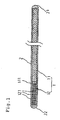
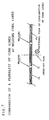
- Fig.1 is a longitudinal sectional view showing an embodiment of the present invention
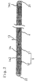
- Fig.2 is a longitudinal sectional view showing another embodiment of the present invention.
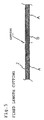
- Fig.3 to Fig.6 are explanatory views of fabrication steps of a guide wire as shown in Fig.1
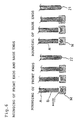
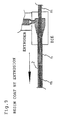
- Fig.7 to Fig.11 are explanatory views of fabrication steps of a guide wire as shown in Fig.2.
- a guide wire according to the present invention includes a core wire 1 having a core body portion 11 having a relatively large sectional area and a distal end portion 12 provided at a distal end 111 of the core body portion 11 and having a relatively small sectional area, at least the distal end portion 12 comprising a sparse bundle of a plurality of slender wire filaments 121 and having substantially no stepped difference (surface) between the distal end portion 12 and the core body portion 11, and a resin layer 2 coated on the core wire 1.
- the core wire 1 comprises core body portion 11 and distal end portion 12 provided at distal end 111 of the core body portion 11.
- Distal end portion 12 comprises a sparse bundle of a plurality of slender wire filaments 121 provided at an end face of the distal end 111 of the core body portion 11 such that an outer periphery of the distal end portion 12 coincides with an outer periphery of the end face.
- the core body portion 11 is a slender wire filament, a cross section of which is formed in a circular shape.
- a diameter (average) of the core body portion 11 is generally about 0.05 mm to 0.1 mm.
- the distal end portion 12 may be constructed such that the plurality of slender wire filaments 121 is previously formed adjacent to the distal end side of the core body portion 11, the distal end portion 12 may be constructed such that the plurality of slender wire filaments 121 is connected with the distal end 111 of the core body portion 11 by welding or the like.
- the diameter of each of the slender wire filaments 121 may be less than half of the diameter of the core body portion 11, a diameter of about a quarter to one eighth thereof is preferable.
- a guide wire shown by Fig.2 comprises a core wire 1 which comprises a plurality of relatively long slender wire filaments 13 existing in an outer portion of the core wire 1 and in both the core body portion 11 and distal end portion 12 and a plurality of relatively short slender wire filaments 14 existing in an inner portion of the core wire 1 and in core body portion 11.
- a number of the slender wire filaments in the distal end portion 12 is less than that of the core body portion 11.
- the slender wire filaments 13 and 14 of the core body portion 11 are bundled and fixed such that proximal sides thereof coincide with each other.
- the distal end portion of the relatively long slender wire filaments 13, that is, portions thereof projected to the outside of, or beyond, the relatively short slender wire filaments 14 constitute the flexible distal end portion 12 after being coated with a resin.
- diameters of the slender wire filaments 13 and 14 may be less than a half of the diameter of the core wire 1, about a quarter to one eighth is preferable.
- the slender wire filaments 13 and 14 can be fixed by welding at least portions of the slender wire filaments 14 including proximal end 141 and distal ends 142 at certain intervals by spot welding (see, Fig.8).
- the guide wire of this type it is efficient to weld the slender wire filaments at certain intervals by spot welding (see, Fig.7), reduce a number of the slender wire filaments, for instance, by a cutter in a certain zone (see, Fig.7 and 8, "n” part), coat the surface of the core wire 1 with a resin (see, Fig.9), cut the reduced part separately (see, Fig.10, "n” part) and round the distal end to thereby form the distal end portion 12 (see Fig.11).
- Super-elastic alloys include nickel series alloys, i.e., nickel-titanium alloys, nickel-titanium-cobalt alloys, nickel-titanium-iron alloys, nickel-aluminum-alloys, nickel-titanium-cobalt alloys; copper series alloys, i.e., copper-aluminum-nickel alloys, copper-zinc alloys, copper-zinc-X alloys (where X: beryllium, silicon, aluminum, or cobalt); titanium series of titanium-palladium-X alloys (where X: chromium, manganese, nickel, iron, cobalt, tungsten, or tantalum), iron series alloys, i.e., iron-manganese alloys and the like.
- High rigidity i.e., nickel-titanium alloys, nickel-titanium-cobalt alloys, nickel-titanium-iron alloys, nickel-aluminum-allo
- a coating material of the core wire there can be adopted polyurethane, polyamide, fluoroplastics including polytetrafluoroethylene, ethylene-tetrafluoroethylene copolymer or the like, polyvinyl chloride, ethylene-vinyl acetate copolymer, silicone, polybutadiene, polyethylene, thermoplastic elastomer and the like.
- the thickness of the coating layer depends on intended use, but generally, is about 0.05 mm to 0.5 mm.
- the diameter of the core wire 1 may be commonly about 0.03 mm to 1.0 mm and, preferably, about 0.05 mm to 0.1 mm for PTCA, or about 0.3 mm to 0.8 mm for angiography.
- the length of the distal end portion 12, the core body portion 11 and the core wire 1 may be selected in accordance with intended use. Usually, the length of the distal end portion 12 is less than that of the core body portion 11.
- a relatively thick slender wire filament A (diameter of 0.45 mm) constituting the core body portion 11 and a sparse bundle B of a plurality of relatively slender wire filaments (diameter of 0.1 mm, five pieces) constituting the distal end portion 12, are fixedly adhered to each other such that an outer periphery of B and an outer periphery of A coincide with each other to thereby form a wire filament member in which A and B are aligned alternately in the order A, B, A, B.
- the wire filament member is subjected to a resin extruder, coated with resin (see, Fig.4) and cut at a center part of A (not shown) and B as illustrated by Fig.5.
- the cut wire filament member coated with a resin is subjected to a die M to round the ends of the wire filament member, to thereby form a distal end 22 (see, Fig. 6, left) and a proximal 21 (see, Fig. 6, right) of the guide wire.
- the resin is positioned and melted in a cavity of the die M, and the cut wire filament member of the sparse bundle B is inserted in the cavity and pulled out from the die M to form the rounded distal end 22 of the distal end portion 12.
- the resin is also positioned and melted in a cavity of the die M, and the cut wire filament member of the thick slender wire filament is inserted in the cave and pulled out from the die M to form the rounded proximal 21 of the core body portion 11.
- a bundle of long slender wire filaments (nine pieces in Fig.7) is prepared, and as illustrated by Fig.7, an appropriate part of the bundle is welded to form a relatively long portion "m" including a weld portion and a relatively short portion "n” not including a weld portion so as to produce repeating segments m-n-m, and to thereby fabricate a wire filament member.
- a plurality of pieces (four pieces in Fig.8) of slender wire filaments (nine pieces in Fig.8) at the relatively short portions "n” are cut axi-symmetrically to thereby form portions corresponding to a flexible distal end portions.
- the wire filament member is subjected to a resin extruder and coated with a resin (see, Fig.9) and thereafter, as shown by Fig.10, cutting is carried out at centers of the weld portions where the relatively long portions "m" are contiguous to each other as well as in the center of the relatively short portions "n". Finally, as illustrated in Fig.11, the cut wire filament member coated with the resin is treated in the die M to thereby round the wire filament member and to thereby form the rounded distal end 22 and the rounded proximal 21 of the guide wire.
- the flexible distal end portion 12 of the guide wire is constructed of a sparse bundle of a plurality of relatively slender wire filaments provided such that the outer periphery of the bundle coincides with the outer periphery of the core body portion 11. Accordingly, there can be formed a guide wire having a flexible distal end portion 12 and having a uniform outer diameter with no stepped difference between the core body portion 11 and the distal end portion 12. Further, by changing the thickness (diameter) of the relatively slender wire filaments or arranging the slender wire filaments sparsely and densely, a directionality can be provided to running of the guide wire.
Description
Claims (3)
- A guide wire having a flexible distal end and comprising a core wire (1) which comprises a core body portion (11) and a distal end portion (12) provided on a distal end of the core body portion (11), the core wire (1) having a uniform outer diameter along its length and substantially no stepped difference between the core body portion (11) and the distal end portion (12),
characterized in that the core body portion (11) is relatively larger in cross section and the distal end portion (12) is relatively smaller in cross section,
in that a resin envelope (2) is covering the core wire (1) , and in that said distal end portion (12) consists essentially of a sparse bundle of a plurality of slender wire filaments. - A guide wire according to claim 1, wherein the distal end portion (12) of the core wire (1) is provided on a distal end of the core body portion (11) such that an outer periphery of the distal end portion (12) coincides with an outer periphery of the distal end of the core body portion (11).
- A guide wire according to claim 1, wherein the core wire (1) comprises a plurality of a relatively long slender wire filaments in an outer portion of the core wire (1) and a plurality of relatively short slender wire filaments in the inner portion of the core wire (1), and the proximal end of the relatively long wire filaments are bundled and fixed to coincide with each other.
Applications Claiming Priority (2)
| Application Number | Priority Date | Filing Date | Title |
|---|---|---|---|
| JP33167599 | 1999-11-22 | ||
| JP33167599A JP2001145699A (en) | 1999-11-22 | 1999-11-22 | Guide wire |
Publications (2)
| Publication Number | Publication Date |
|---|---|
| EP1101507A1 EP1101507A1 (en) | 2001-05-23 |
| EP1101507B1 true EP1101507B1 (en) | 2005-01-12 |
Family
ID=18246336
Family Applications (1)
| Application Number | Title | Priority Date | Filing Date |
|---|---|---|---|
| EP00124394A Expired - Lifetime EP1101507B1 (en) | 1999-11-22 | 2000-11-21 | Guide wire |
Country Status (4)
| Country | Link |
|---|---|
| US (1) | US6464651B1 (en) |
| EP (1) | EP1101507B1 (en) |
| JP (1) | JP2001145699A (en) |
| DE (1) | DE60017338T2 (en) |
Families Citing this family (21)
| Publication number | Priority date | Publication date | Assignee | Title |
|---|---|---|---|---|
| US6918882B2 (en) * | 2001-10-05 | 2005-07-19 | Scimed Life Systems, Inc. | Guidewire with stiffness blending connection |
| EP1432467B1 (en) * | 2001-10-05 | 2005-12-14 | Boston Scientific Limited | Composite guidewire |
| JP4740741B2 (en) * | 2003-12-19 | 2011-08-03 | 学校法人慶應義塾 | Medical guide wire coated with carbon film |
| JP4834367B2 (en) * | 2005-09-29 | 2011-12-14 | 日本ライフライン株式会社 | Guide wire and manufacturing method thereof |
| US8152742B2 (en) * | 2006-05-01 | 2012-04-10 | Boston Scientific Scimed, Inc. | Crossing guide wire with corrugated shaping ribbon |
| US8622931B2 (en) * | 2007-02-09 | 2014-01-07 | Boston Scientific Scimed, Inc. | Extruded guidewires and methods of making |
| US11406791B2 (en) | 2009-04-03 | 2022-08-09 | Scientia Vascular, Inc. | Micro-fabricated guidewire devices having varying diameters |
| US10363389B2 (en) * | 2009-04-03 | 2019-07-30 | Scientia Vascular, Llc | Micro-fabricated guidewire devices having varying diameters |
| CN102639303B (en) | 2008-12-08 | 2015-09-30 | 血管科学有限公司 | For forming micro-cutting machine of otch in the product |
| US9616195B2 (en) * | 2009-04-03 | 2017-04-11 | Scientia Vascular, Llc | Micro-fabricated catheter devices having varying diameters |
| US9067333B2 (en) | 2009-04-03 | 2015-06-30 | Scientia Vascular, Llc | Micro-fabricated guidewire devices having elastomeric fill compositions |
| US9072873B2 (en) * | 2009-04-03 | 2015-07-07 | Scientia Vascular, Llc | Micro-fabricated guidewire devices having elastomeric compositions |
| US20100256603A1 (en) * | 2009-04-03 | 2010-10-07 | Scientia Vascular, Llc | Micro-fabricated Catheter Devices Formed Having Elastomeric Fill Compositions |
| US9950137B2 (en) * | 2009-04-03 | 2018-04-24 | Scientia Vascular, Llc | Micro-fabricated guidewire devices formed with hybrid materials |
| US11207502B2 (en) | 2016-07-18 | 2021-12-28 | Scientia Vascular, Llc | Guidewire devices having shapeable tips and bypass cuts |
| US11052228B2 (en) | 2016-07-18 | 2021-07-06 | Scientia Vascular, Llc | Guidewire devices having shapeable tips and bypass cuts |
| US10821268B2 (en) | 2016-09-14 | 2020-11-03 | Scientia Vascular, Llc | Integrated coil vascular devices |
| US11452541B2 (en) | 2016-12-22 | 2022-09-27 | Scientia Vascular, Inc. | Intravascular device having a selectively deflectable tip |
| WO2018129455A1 (en) | 2017-01-09 | 2018-07-12 | Boston Scientific Scimed, Inc. | Guidewire with tactile feel |
| EP3842091B1 (en) | 2017-05-26 | 2023-09-13 | Scientia Vascular, Inc. | Micro-fabricated medical device having a non-helical cut arrangement |
| US11305095B2 (en) | 2018-02-22 | 2022-04-19 | Scientia Vascular, Llc | Microfabricated catheter having an intermediate preferred bending section |
Family Cites Families (7)
| Publication number | Priority date | Publication date | Assignee | Title |
|---|---|---|---|---|
| US4682607A (en) * | 1985-12-02 | 1987-07-28 | Vlv Associates | Wire guide |
| US4739768B2 (en) * | 1986-06-02 | 1995-10-24 | Target Therapeutics Inc | Catheter for guide-wire tracking |
| JP2516444B2 (en) * | 1990-02-06 | 1996-07-24 | テルモ株式会社 | Guide wire for catheter |
| US5251640A (en) * | 1992-03-31 | 1993-10-12 | Cook, Incorporated | Composite wire guide shaft |
| US5833631A (en) * | 1996-06-28 | 1998-11-10 | Target Therapeutics, Inc. | Fiber tip guidewire |
| DE69707789T2 (en) * | 1996-08-28 | 2002-05-02 | Asahi Intecc Co | guidewire |
| NL1005662C2 (en) * | 1997-03-27 | 1998-09-29 | Cordis Europ | Guide wire. |
-
1999
- 1999-11-22 JP JP33167599A patent/JP2001145699A/en active Pending
-
2000
- 2000-11-21 DE DE60017338T patent/DE60017338T2/en not_active Expired - Fee Related
- 2000-11-21 EP EP00124394A patent/EP1101507B1/en not_active Expired - Lifetime
- 2000-11-22 US US09/717,266 patent/US6464651B1/en not_active Expired - Fee Related
Also Published As
| Publication number | Publication date |
|---|---|
| EP1101507A1 (en) | 2001-05-23 |
| US6464651B1 (en) | 2002-10-15 |
| DE60017338D1 (en) | 2005-02-17 |
| DE60017338T2 (en) | 2005-06-02 |
| JP2001145699A (en) | 2001-05-29 |
Similar Documents
| Publication | Publication Date | Title |
|---|---|---|
| EP1101507B1 (en) | Guide wire | |
| US4842590A (en) | Catheter and method for making | |
| US7713259B2 (en) | Guiding catheter shaft with improved radiopacity on the wire braid | |
| EP1325763B1 (en) | Guide wire | |
| US8465469B2 (en) | Reinforced catheter and methods of making | |
| EP1955724B1 (en) | Medical catheter | |
| US6562022B2 (en) | Catheter with enhanced reinforcement | |
| US6103037A (en) | Method for making a catheter having overlapping welds | |
| US6866660B2 (en) | Intravascular catheter with composite reinforcement | |
| US6171297B1 (en) | Radiopaque catheter tip | |
| JP4368678B2 (en) | Integrated polymer and braid for intravascular catheters | |
| DE69821956T2 (en) | Delivery catheter for peripheral blood vessels | |
| EP0608853B1 (en) | Vascular dilatation instrument and catheter | |
| DE60313805T2 (en) | Controllable catheter | |
| EP0661072B1 (en) | Catheter | |
| US8551020B2 (en) | Crossing guidewire | |
| US20040087933A1 (en) | Stiff guiding catheter liner material | |
| EP0334640A2 (en) | Soft tip catheters | |
| JPH08733A (en) | Blood vessel catheter | |
| CA2358661A1 (en) | Intravascular catheter with composite reinforcement | |
| WO1999048548A1 (en) | Catheter having extruded radiopaque stripes embedded in soft tip and method of fabrication | |
| WO1997037713A1 (en) | Thin-walled and braid-reinforced catheter | |
| CN211863554U (en) | Catheter sheath | |
| CN113908403B (en) | Intracranial catheter | |
| JPH1076014A (en) | Guide wire |
Legal Events
| Date | Code | Title | Description |
|---|---|---|---|
| PUAI | Public reference made under article 153(3) epc to a published international application that has entered the european phase |
Free format text: ORIGINAL CODE: 0009012 |
|
| AK | Designated contracting states |
Kind code of ref document: A1 Designated state(s): DE FR GB IT |
|
| AX | Request for extension of the european patent |
Free format text: AL;LT;LV;MK;RO;SI |
|
| RAP1 | Party data changed (applicant data changed or rights of an application transferred) |
Owner name: NIPRO CORPORATION |
|
| 17P | Request for examination filed |
Effective date: 20010717 |
|
| AKX | Designation fees paid |
Free format text: DE FR GB IT |
|
| 17Q | First examination report despatched |
Effective date: 20031107 |
|
| GRAP | Despatch of communication of intention to grant a patent |
Free format text: ORIGINAL CODE: EPIDOSNIGR1 |
|
| GRAS | Grant fee paid |
Free format text: ORIGINAL CODE: EPIDOSNIGR3 |
|
| GRAA | (expected) grant |
Free format text: ORIGINAL CODE: 0009210 |
|
| AK | Designated contracting states |
Kind code of ref document: B1 Designated state(s): DE FR GB IT |
|
| REG | Reference to a national code |
Ref country code: GB Ref legal event code: FG4D |
|
| REF | Corresponds to: |
Ref document number: 60017338 Country of ref document: DE Date of ref document: 20050217 Kind code of ref document: P |
|
| PLBE | No opposition filed within time limit |
Free format text: ORIGINAL CODE: 0009261 |
|
| STAA | Information on the status of an ep patent application or granted ep patent |
Free format text: STATUS: NO OPPOSITION FILED WITHIN TIME LIMIT |
|
| PG25 | Lapsed in a contracting state [announced via postgrant information from national office to epo] |
Ref country code: IT Free format text: LAPSE BECAUSE OF NON-PAYMENT OF DUE FEES Effective date: 20051121 Ref country code: GB Free format text: LAPSE BECAUSE OF NON-PAYMENT OF DUE FEES Effective date: 20051121 |
|
| ET | Fr: translation filed | ||
| 26N | No opposition filed |
Effective date: 20051013 |
|
| PG25 | Lapsed in a contracting state [announced via postgrant information from national office to epo] |
Ref country code: DE Free format text: LAPSE BECAUSE OF NON-PAYMENT OF DUE FEES Effective date: 20060601 |
|
| GBPC | Gb: european patent ceased through non-payment of renewal fee |
Effective date: 20051121 |
|
| PG25 | Lapsed in a contracting state [announced via postgrant information from national office to epo] |
Ref country code: FR Free format text: LAPSE BECAUSE OF NON-PAYMENT OF DUE FEES Effective date: 20060731 |
|
| REG | Reference to a national code |
Ref country code: FR Ref legal event code: ST Effective date: 20060731 |