EP1101351B1 - Tete de scanneur pour le balayage de documents - Google Patents
Tete de scanneur pour le balayage de documents Download PDFInfo
- Publication number
- EP1101351B1 EP1101351B1 EP99931111A EP99931111A EP1101351B1 EP 1101351 B1 EP1101351 B1 EP 1101351B1 EP 99931111 A EP99931111 A EP 99931111A EP 99931111 A EP99931111 A EP 99931111A EP 1101351 B1 EP1101351 B1 EP 1101351B1
- Authority
- EP
- European Patent Office
- Prior art keywords
- line
- original
- template
- optical system
- optics
- Prior art date
- Legal status (The legal status is an assumption and is not a legal conclusion. Google has not performed a legal analysis and makes no representation as to the accuracy of the status listed.)
- Expired - Lifetime
Links
Images


Classifications
-
- H—ELECTRICITY
- H04—ELECTRIC COMMUNICATION TECHNIQUE
- H04N—PICTORIAL COMMUNICATION, e.g. TELEVISION
- H04N1/00—Scanning, transmission or reproduction of documents or the like, e.g. facsimile transmission; Details thereof
- H04N1/04—Scanning arrangements, i.e. arrangements for the displacement of active reading or reproducing elements relative to the original or reproducing medium, or vice versa
- H04N1/12—Scanning arrangements, i.e. arrangements for the displacement of active reading or reproducing elements relative to the original or reproducing medium, or vice versa using the sheet-feed movement or the medium-advance or the drum-rotation movement as the slow scanning component, e.g. arrangements for the main-scanning
- H04N1/126—Arrangements for the main scanning
- H04N1/129—Arrangements for the main scanning using an element rotating or oscillating about an axis not covered by any other group or code
-
- G—PHYSICS
- G02—OPTICS
- G02B—OPTICAL ELEMENTS, SYSTEMS OR APPARATUS
- G02B26/00—Optical devices or arrangements for the control of light using movable or deformable optical elements
- G02B26/08—Optical devices or arrangements for the control of light using movable or deformable optical elements for controlling the direction of light
- G02B26/10—Scanning systems
-
- H—ELECTRICITY
- H04—ELECTRIC COMMUNICATION TECHNIQUE
- H04N—PICTORIAL COMMUNICATION, e.g. TELEVISION
- H04N1/00—Scanning, transmission or reproduction of documents or the like, e.g. facsimile transmission; Details thereof
- H04N1/04—Scanning arrangements, i.e. arrangements for the displacement of active reading or reproducing elements relative to the original or reproducing medium, or vice versa
- H04N1/10—Scanning arrangements, i.e. arrangements for the displacement of active reading or reproducing elements relative to the original or reproducing medium, or vice versa using flat picture-bearing surfaces
-
- H—ELECTRICITY
- H04—ELECTRIC COMMUNICATION TECHNIQUE
- H04N—PICTORIAL COMMUNICATION, e.g. TELEVISION
- H04N1/00—Scanning, transmission or reproduction of documents or the like, e.g. facsimile transmission; Details thereof
- H04N1/04—Scanning arrangements, i.e. arrangements for the displacement of active reading or reproducing elements relative to the original or reproducing medium, or vice versa
- H04N1/113—Scanning arrangements, i.e. arrangements for the displacement of active reading or reproducing elements relative to the original or reproducing medium, or vice versa using oscillating or rotating mirrors
-
- H—ELECTRICITY
- H04—ELECTRIC COMMUNICATION TECHNIQUE
- H04N—PICTORIAL COMMUNICATION, e.g. TELEVISION
- H04N1/00—Scanning, transmission or reproduction of documents or the like, e.g. facsimile transmission; Details thereof
- H04N1/04—Scanning arrangements, i.e. arrangements for the displacement of active reading or reproducing elements relative to the original or reproducing medium, or vice versa
- H04N1/19—Scanning arrangements, i.e. arrangements for the displacement of active reading or reproducing elements relative to the original or reproducing medium, or vice versa using multi-element arrays
- H04N1/191—Scanning arrangements, i.e. arrangements for the displacement of active reading or reproducing elements relative to the original or reproducing medium, or vice versa using multi-element arrays the array comprising a one-dimensional array, or a combination of one-dimensional arrays, or a substantially one-dimensional array, e.g. an array of staggered elements
- H04N1/192—Simultaneously or substantially simultaneously scanning picture elements on one main scanning line
- H04N1/193—Simultaneously or substantially simultaneously scanning picture elements on one main scanning line using electrically scanned linear arrays, e.g. linear CCD arrays
Definitions
- the invention relates to a device with which it is possible to optically scan a template, to create a technical image of the template in terms of brightness or color to be able to.
- Devices for optical scanning of documents for conversion into electronic Signals are used in so-called scanners, for example in so-called laser scanners for barcode recording, as used in cash registers for recording article numbers are, in swipe scanners, as are usual with fax machines, in hand scanners and flatbed scanners, such as those used to record the template and to store a data technology Image of the template in computers for further processing of images, drawings or texts of the template are used.
- Optical devices Scanning of originals are also used in photocopiers to image the whole Template used on a photosensitive drum.
- Solutions that implement the second basic principle can be divided into two groups, the first of which is characterized by that in an electronic video camera through optics a two-dimensional image of the Thrown original on a surface image sensor and this is scanned by electronics , whereby the brightness and color information of so-called picture elements or pixels divided into rows and columns according to the image elements of the sensor is made available serially for further processing, while in the second Group in an electronic line scan camera only a one-dimensional image of the template, So a line of the template, thrown onto a line sensor and this by means of electronics is scanned, whereby the brightness and color information of the picture elements or pixels serialized according to the image elements of the sensor only in columns is made available for further processing while the division into lines be made by a relative movement between the original and the line scan camera got to.
- the relative movement of the sensor line over the template is indicated by a in the hand scanner smooth and even pulling of the hand scanner lying on the template over the submission reached. Illumination in the form of a narrow one passes through Light-emitting diodes produced the light strip, the one reflected by the original Light that contains the color and brightness information is switched off by a hand scanner fixed mirrors and lenses existing optics on the CCD line sensor projected so that it can evaluate a line of the template.
- a fold of the Beam path with the optics allows a relatively long line, for example 4 inches long, map to a relatively short sensor and small fluctuations in distance due to relative to compensate for large depth of field.
- the template rolling roller helps to create a straight and non-edged one Relative movement of the hand scanner to the original, on the other hand, the angle of rotation of the Roll recorded and evaluated by incremental encoder. So can the relative position of each line entered on the template.
- the one on the template rolling roller driven so that the relative movement by pulling the submission is effected by the scanner.
- the original lies with the side to be scanned on a glass plate, while on the other side of this glass plate one that corresponds to the hand scanner Unit of lighting, optics and CCD line sensor on a parallel to the glass plate
- the guide is moved without being edged by a drive.
- an image-sensitive one for imaging an original Drum preferably two methods, namely first a synchronous movement of submission and drum, with a narrower in the longitudinal direction of the submission, the entire Width of the template comprehensive strip-shaped area of the template on a narrow Stripes of the cylinder can be imaged sharply, the stripe-shaped area the entire length of the template due to the synchronous movement of the template and cylinder scanned and mapped to the circumference of the cylinder, and secondly a scan the template over a system of two mirrors, the first mirror over the full Length of the original, the second mirror only moved half a way, and the Radiation path is guided so that the distance between the original and the imaging optics Projection of the original on the rotating in sync with the linear movement of the mirror Drum, measured along the beam path, remains constant and so the template by a narrow, strip-like one that moves along the length of the original Area is sharply imaged on the lateral surface of the drum.
- Scanners are also known which require a cylindrical shape of the original or force to scan the original by rotating lighting, imaging optics and sensor to implement an axis.
- EP 0 670 555 A1 shows that an area sensor also relates to an area can be moved, and then how the data-technical image of the surface is obtained and can be processed. The movement of a design designed as a pin over the surface of the template is done by hand.
- EP 0 164 713 A1 shows how the distance of a sensor line from a plane to be scanned template can be kept constant in that a rolling body on end of a rod embodying this distance next to the original one parallel to this and located at a distance from the rolling radius of the rolling body Path is guided, while the other end of the rod up and down by a linear guide is dissipated.
- DE - A - 32 16 736 shows a device for deflecting and directing a received radiation, in which a mirror is attached to a carrier.
- the carrier is arranged on two points, each with different Rotation factors run on curved tracks, with the mirror rotating at the same time and is moved (see especially Figure 5).
- the invention has the task, in a small and inexpensive to manufacture, on one level template in a fixed position on the surface of the template to map a line sensor that one for one for the individual lines of the template sharp image sufficient constant distance between original and optics as well between optics and line sensor is observed.
- Continuous reading of the information of the line sensor is to be a data-technical image of the entire area of the surface of the original intended for scanning for further Provide processing.
- the lighting should be such that the A sufficiently bright and high-contrast image is created on the surface of the line sensor, not due to reflections from components of the device or the surface of the original is disturbed without the need to accommodate lighting and imaging optics necessary space requires the use of an unwieldy housing.
- an implementation of the invention is said to be an inexpensive and robust mechanical construction allow.
- a particularly favorable embodiment of the invention is achieved in that a line sensor, an imaging optics and a lighting device in a fixed arrangement an optics carrier combined into a mechanical part, which is so with respect to a template can be moved that points of the optical axis of the imaging optics on a Move the v-shaped web so that the distance between the original and the line sensor at Scanning this measured along the optical axis remains essentially the same.
- a line sensor, an imaging optics and a lighting device in a fixed arrangement an optics carrier combined into a mechanical part, which is so with respect to a template can be moved that points of the optical axis of the imaging optics on a Move the v-shaped web so that the distance between the original and the line sensor at Scanning this measured along the optical axis remains essentially the same.
- a sensor drum can also be selected, the axis of rotation of which with respect to imaging optics and lighting device in the optics carrier is.
- the scanning head designed with it cannot be used for photocopying machines either moving template 10 are used to a design with a small footprint enable.
- a device can be implemented with linear guides.
- One guide can lie in the plane of the template, the second one in an inclined, preferably vertical plane.
- the movement of points on the optical axis between the linear guides are V-shaped, those of the linear guides are of course linear.
- the production of linear guides is complex, only small play of the guides difficult to reach and the friction to be overcome is relatively large. So one becomes special favorable embodiment of the invention achieved with the use of a four-bar linkage, its four sides by two spherical bearings, which are in a housing of the device the template are firmly positioned by two arms mounted in these spherical bearings and through an optics carrier on which the two arms are supported in spherical bearings, are defined.
- the dimensions according to the invention permits a largely free dimensioning Definition of important reference dimensions, such as the distance of all parts from the template, the angular range for the relative inclination of the optical axis to the original and the one to be scanned Width of the template, and achieved slight deviations from the optics to the line sensor sharply depicted lines from the level of the template and thus a small required Depth of field. So the clear diameter of the optics can be chosen relatively large which causes the blurring of the image caused by diffraction at the optics is reduced and the light beam imaged by the template onto the line sensor is widened. This means that more brightness is available on the line sensor. This can be used for this are to increase the scanning speed and / or the lighting device with to operate with lower light output.
- a favorable design of the invention is achieved in that the lighting necessary light output by the same optics, which also the image of the template on the Sensor, focuses on the original.
- the illuminating beam and mirror can be achieved that the illuminating beam hits the original at an angle that results in only backscattered but not reflected light hits the line sensor.
- the achievement of a narrow, but at least the line length reaching light spot, a so-called Light bar on the template with suitable lenses or mirrors in the beam path can be achieved, for example by cylindrical lenses or curved mirrors.
- the optics carrier can be designed in such a way that it represents a box tapering towards the original, which includes of its possible movements occupies a space that does not or at least not much wider than the original and mechanically very stable.
- a circuit board can be attached, for example next to the line sensor.
- a particularly small design can be achieved if the beam path between Optics and line sensor is folded.
- conventional line sensors have housing dimensions of 10 mm by 40 mm. With a line length of 20 mm, for example So the line sensor is twice as long, so that when the beam path is not folded one Thickness of the housing of over 40 mm results.
- a reduction in the dimensions of the The line sensor is only possible to a limited extent because the sensor areas also become smaller and required amounts of light and image sharpness would have to increase.
- the illuminating beam can also be included in the folded beam path be so that the light sources used for lighting continue to be next to the line sensor can be arranged.
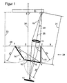
- Figure 1 shows a particularly favorable embodiment of the invention using a four-bar linkage in a schematic representation and an arbitrary position.
- the quadrilateral joint 28 lies in the representation plane.
- the quadrilateral joint encompasses the two the template 10 fixed hinge points 1 and 2 and the movable hinge points 3 and 4.
- the distance 21 between points 1 and 3 is L1, the distance 22 between points 2 and 4 with L2, the distance 23 between points 3 and 4 with L3 and the distance 24 between points 1 and 4 designated L4.
- the axes of rotation of the four-bar linkage 28 are located at the pivot points 1 to 4 and are perpendicular to the display plane.
- template 10 whose lines and the line sensor 13 are arranged perpendicular to the display plane.
- Point 6 The center point of the route from pivot point 3 to pivot point 4 is as point 6, which is the Template closer point with the distance 31, also referred to as L5, to this route in Point 6 is named as point 7.
- Point 7 represents the point from which light emanates within the light beam 19, 20 with the optical axis 25 through the optics 11 on the Line sensor 13 is focused.
- the side of the template 10 to be scanned facing the optics 11 is parallel to the X axis 29 of the coordinate system aligned, the middle line of the template has the position 5.
- Optics 11 and line sensor 13 have one with respect to the route from point 3 to point 4 fixed position, are centered and perpendicular to the perpendicular line of this route.
- the angle ⁇ is that between the distance from pivot point 2 to pivot point 1 and the from hinge point 2 to hinge point 4, the angle ⁇ is that between the distance from Joint point 1 after joint point 2 and that from joint point 1 to joint point 4, the Angle ⁇ is that between the distance from pivot point 1 to pivot point 4 and that of Joint point 1 after joint point 3, the angle ⁇ is that between the distance from the joint point 1 after hinge point 2 and from hinge point 3 to hinge point 4, thus also the between the optical axis 25 from point 7 to point 6 and the plumb line on the template 10th
- P5y 64
- all dimensions can be exemplary in millimeters.
- L1 and so L2 are usually chosen so that the articulation points 1 and 2 are not behind the template lie, i.e. P1y and P2y are not larger than P5y.
- Table 1 shows the result values for certain values of the angle ⁇ shown, the resolution of the representation of the values in the table at the coordinates of point 7 was chosen to be 1/100 mm, while the coordinates of the others Points are given only with 1mm resolution, to approximate the position of the points describe.
- the optimization is for using the depth of field Imaging optics of +/- 0.11 mm and a width of 70 mm to be used accordingly a range for P7x from -35 mm to +35 mm and for P7y from 64.11 mm to 63.89 mm Have been carried out.
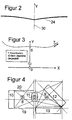
- Figure 2 shows the v-shaped course of point 6 with the above dimensioning, but on a different scale than Figure 1. If the center position of the line sensor 13 were chosen on the optical axis, the extension of the v-shaped path in the X direction would be less , more pronounced in the Y direction.
- FIG. 3 shows the resulting path of point 7, which would ideally lie on a straight line, the Y coordinates being shown ten times too high, because otherwise the deviations from the Y coordinate of point 5 would hardly be recognizable in the figure.
- a core area of the scanning is achieved with particularly high precision of the image of the template 10 on the line sensor 13 and an edge area adjoining this area on the outside with lower requirements to realize the precision of the mapping of the template 10 onto the line sensor 13, the edge area during the scanning to detect coarser structures of the original 10, such as edge detection or to describe the presentation of coarsely coded data, while the core area is scanned at full resolution.
- the core area includes an area for P7x from -32.2 mm to +32.2 mm with P2y from -64.11 mm to -64.00 mm, while the edge area has an area for P7x of -35 mm to -32.2 mm and +32.2 mm to +35 mm with P2y from -64.00 mm to -63.89 mm.
- the relevant position for the positioning of the template 10 is Point 5 optimally for P5x from 64.05 mm to 64.06 mm, whereby the distance of the Point 7 of the template 10 remains smaller than 0.06 mm in the core area and Chebyshev characteristic has, while it does not exceed 0.16 mm in the edge area.
- Typical line sensors 13, for example SONY ILX503A have a line length of 2048 pixels, so-called pixels, with a pixel size of 14 ⁇ m and one Grid spacing of 14 ⁇ m. If the line length to be detected by the line sensor is one is 20.48 mm perpendicular to the line 27 of the template, this results in with linear imaging through the optics 11, a necessary magnification of 1.4 or a 10 ⁇ m by 10 ⁇ m pixel size based on the original 10 with a Grid spacing of 10 ⁇ m.
- FIG. 4 shows a section perpendicular to the reference plane of FIG. 1 in points 6 and 7 of an embodiment of the invention.
- a comparatively long line sensor 13 which in the example has an outer mechanical length of approximately 42 mm and a line length of 2048 by 14 ⁇ m, 28,672 mm, can be accommodated in a space-saving manner. Only the light-sensitive part of the line sensor 13 is shown in FIG. What is essential is the lateral displacement of the optics 11 with respect to the template 10 and the use of a mirror 12. The dimensions shown result when the optics 11 with a focal length of 12.5 mm, a diameter of 9.5 mm and a distance between the main planes 17, 18 by 1.8 mm is used. The beam path is shown in the usual international manner.
- FIG. 5 shows the view of the reference plane of FIG. 1 with the configuration shown in FIG. 4 for an arbitrary angle ⁇ .
- the object G to be imaged is imaged into the image B by the optics 11, the distance between the object G and the first main plane 17 as the object width g, that between the second main plane 18 and the image B as the image width b and that between the two Main planes 17 and 18 is referred to as the main plane distance h.
- the beams between the two main planes 17 and 18 are assumed to be parallel to the optical axis, the straight line through the two focal points 8 and 9 being considered as the optical axis.
- the diameter of the optics 11 is not important, so that the representation of the beams involved is of no importance for the construction of the image from the object to the image.
- a major advantage of the invention is that optics 11, mirror 12 and line sensor 13 can be mounted in a rigid optics carrier 16 and adjusted if necessary, of the axes corresponding to the articulation points 3 and 4 of the articulated square 28 is stored.
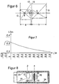
- FIG. 7 shows the Bezier curve for determining the dimension L3m, which is required to carry out the method according to the invention for calculating the length 23, L3. With the specified data, the determination can also be carried out mathematically in a generally known manner.
- the reference dimension 33 can be defined the maximum extent of the device according to the invention between template 10 and Quadrangle 28 corresponds to the Y axis 30 of the coordinate system.
- the distance P5y of the coordinate origin 0 and thus the fixed articulation points 1 and 2 can be selected from the template 10, with a location as close as possible to the template 10 results in a particularly wide scanning field.
- the possible scanning width of the template 10 results from the maximum value of the deflection of the point 7 in the X direction P7x (max) belonging to the required accuracy, for which the distance to the template 10, that is
- P7x (max) can be estimated: P7x (max) ⁇ L0 * (0.58333 - 0.175 * P5y / L0 -0.18 * (P5y / L0) ⁇ 2)
- the position P1x, P2x of the two fixed articulation points 1, 2 of the quadrangle 28 can be selected.
- L0 is chosen with 60 mm, P2x with 25 mm and P5y with 15 mm.
- P2x (max) results in 55 mm, so it is adhered to, P7x (max) in approx 31.7 mm, so sufficient.
- L1 results in 45 mm, Xx in 0.41667, Vxx in -0.38326, Vy to -0.17603 and V to 0.88711. This calculates L1m to be 0.32534.
- In the Bezier curve can be read L3m to 0.2782. This results in L3 to 27.2538 mm.
- a check with fine optimization results in a scan width of 60 mm a value for P7x of 30 mm is a maximum difference
- the optical axis In order to angle ⁇ is adjusted to 92.1 degrees, the optical axis reaches an inclination ⁇ to Template 10 by 14.8 degrees.
- the optical axis passes through the point in the peripheral position (26, 0), the bearing of the second fixed hinge point 2 must not be in the area of the effective light beam between 19 and 20 protrude. This can be achieved in that As can be seen in FIG.
- the articulation points 1 and 2 are sufficiently far from the template 10 removed and / or positioned sufficiently far in the X direction, or in that the movable square sides 14, 15 in the form of a tuning fork have their fixed articulation points 1, 2 have sufficiently far above and below the effective light beam.
- FIG. 8 a section parallel to the Y axis 30 and perpendicular to the reference plane of FIG. 1 at an ⁇ of 90 degrees is shown as an example, like the bearings for the first and second movable square sides 14, 15 belonging to the fixed articulation points 1, 2 by shaping the housing 34 and the bearings belonging to the movable articulation points 3, 4 between the first and second movable arms 14, 15 and the third movable square side, the optics carrier 16 can be formed by a bearing pin 35.
- FIG. 9 shows how a light bundle for illumination, which also uses the optics 11 for focusing on the original, can be guided using several mirrors 37, 38, two in the example shown.
- the delimited boundary 39 of the light bundle represents a particularly wide light bundle including the positional tolerances of the mirrors 37, 38 which have to be taken into account and which result in the maximum inclination of the optical axis 36 caused by the maximum value of the angle ⁇ of the optical axis 25 in relation to the original 10 of the light beam with respect to the template 10 when the template 10 is reached by the light beam.
- FIG. 10 shows which angular range the lateral boundaries 19, 20 of the effective light beam cover from the original 10 via the optics 11 to the line sensor 13 before the optics 11 are reached. This area is kept free from the radiation of the light beam of the illumination in FIG. 8 reflected by the template 10.
- the clear width of the optics 11 is determined to deviate from the circle, for example in the form of a rectangle in which the long side runs parallel to the line. In this way, the light bundles shown in FIGS. 9 and 10 can be made narrower and the light bundle of the illumination can strike the template more steeply.
- a diameter of the optics 11 of 8 mm there is an optical cross section of 50 mm 2 , with a rectangle of 8 mm * 4 mm a cross section of 32 mm 2 , i.e. of 64 percent with a reduction in the angle to half while it would have been only 25 percent with a diameter of 4 mm.
- the diffraction limit should be considered as the limit of the narrowing.
- a favorable choice of the inclination of the mirrors 37 and 38 can achieve that the mirrors are relatively close to the lateral boundaries 19, 20 of the effective light beam arrange and thus the dimensions of the housing 34 in the direction of the X-axis 29 in the area between template 10 and optics 11.
- LEDs light emitting diodes
- LEDs light emitting diodes
- you-called LEDs suitable. If you use this on the side of the optics away from the original 11 with the optics 11 rotated and / or offset relative to the optical axis 25 optical axis 36, so you can by appropriate positioning of the LED and by Choice of the focal length, position and orientation of a cylindrical lens in the beam path of the Beams of lighting achieve that the image of the light-emitting surface of the LED on template 10 as a light line or narrow bar the line to be displayed illuminated.
- the use of several LEDs can also be done with a common cylindrical lens serve to increase the light intensity and / or to even out.
- the use of two mirrors 37, 38 shown in FIG. 8 can be symmetrical on both sides be expanded.
- the two mirrors 37, 38 on either side be positioned and extended so that a joint kinked component can be.
- this ensures that, on the one hand, the penetration of extraneous light is largely suppressed in the optical range, that for the second at Verbund of the two mirror combinations 37, 38 with a floor and / or ceiling plate as third movable square side, as optics carrier 16 in the form of a mechanically stable movable part can be designed.
- the mirrors 37, 38 can also be curved, depending on the configuration even without a kink, but with a smooth transition, so that only one Mirror is recognizable on each side. This eliminates the need for a cylindrical lens.
Landscapes
- Engineering & Computer Science (AREA)
- Multimedia (AREA)
- Signal Processing (AREA)
- Physics & Mathematics (AREA)
- General Physics & Mathematics (AREA)
- Optics & Photonics (AREA)
- Facsimile Scanning Arrangements (AREA)
- Facsimile Heads (AREA)
- Mechanical Optical Scanning Systems (AREA)
- Adjustment Of The Magnetic Head Position Track Following On Tapes (AREA)
- Apparatus For Radiation Diagnosis (AREA)
Claims (10)
- Dispositif pour le balayage optique ligne par ligne d'un motif (10) plan avec la reproduction d'une longueur de ligne entière du motif (10) sur un détecteur (13) par un système optique (11) fixé sur un support de système optique (16) et/ou sur un miroir (12) fixé sur ce support (16), dans lequel on fait bouger un point (6) de l'axe optique en tant que point de référence entre la ligne et le détecteur de lignes (13) sur un parcours en forme de V, caractérisé en ce que le support de système optique (16) est disposé entre deux points (3, 4) qui suivent chacun des parcours courbe.
- Dispositif selon la revendication 1, caractérisé en ce que le support de système optique (16) se présente sous la forme d'un bras central d'un quadrilatère symétrique articulé (1 ; 2 ; 3 ; 4).
- Dispositif selon la revendication 1 ou 2, caractérisé en ce que deux points d'articulation (1 ; 2) du quadrilatère articulé (1 ; 2 ; 3 ; 4) sont positionnés parallèlement au motif (10) et en ce que la distance L3 entre les points d'articulation (3 ; 4) du support de système optique (16) est dimensionné selon le schéma suivant, dans lequel L0 est la distance maximale entre les points d'articulation (3 ; 4) et le motif (10), et L1 est la longueur des côtés mobiles (14 ; 15) du quadrilatère articulé (1 ; 2 ; 3 ; 4), P2x étant la valeur x sur l'abscisse du point P2 :a)b)c)d)e)f) A l'aide des points
(-0,1625, 0,3)
(-0,13125, 0,46458)
(0,01146, 0,25625)
(1,0, 0,2151),
caractérisant la courbe de Bézier à deux dimensions L1m, L3m, on détermine la valeur L3m correspondant à L1m.g) - Dispositif selon au moins l'une des revendications 1 à 3, caractérisé en ce qu'un dispositif d'éclairage est disposé sur le support de système optique (16) afin d'éclairer chacune des lignes à balayer du motif (10).
- Dispositif selon la revendication 4, caractérisé en ce que l'éclairage a lieu à travers le système optique (11) avec un axe optique incliné ou décalé par rapport à son axe optique et une barre lumineuse produite par le dispositif d'éclairage est réfléchie par un ou plusieurs miroirs (37, 38) sur les lignes à éclairer du motif (10).
- Dispositif selon la revendication 5, caractérisé en ce qu'au moins un miroir (37 et/ou 38) est courbe.
- Dispositif selon la revendication 5 ou 6, caractérisé en ce que deux surfaces de miroir sont réunies en un miroir commun.
- Dispositif selon au moins une l'une des revendications 1 à 7, caractérisé en ce que le détecteur (13) est un cylindre détecteur dont l'axe est disposé de manière fixe dans le support de système optique (16).
- Dispositif selon au moins l'une des revendications 1 à 8, caractérisé en ce qu'un faisceau lumineux partant d'une ligne à balayer est dévié par un miroir ou un prisme après avoir traversé le système optique (11) et la surface du détecteur de lignes (13) est inclinée par rapport à un plan perpendiculaire à l'axe optique, de préférence perpendiculaire au motif (10).
- Dispositif selon au moins l'une des revendications 1 à 9, caractérisé en ce que la largeur d'ouverture du système optique (11) parallèle à la ligne à reproduire, est plus grande que celle dans le sens perpendiculaire à celle-ci.
Applications Claiming Priority (3)
| Application Number | Priority Date | Filing Date | Title |
|---|---|---|---|
| DE19829776 | 1998-07-03 | ||
| DE19829776A DE19829776C1 (de) | 1998-07-03 | 1998-07-03 | Scannerkopf zur Abtastung von Vorlagen |
| PCT/EP1999/004264 WO2000002376A1 (fr) | 1998-07-03 | 1999-06-19 | Tete de scanneur pour le balayage de documents |
Publications (2)
| Publication Number | Publication Date |
|---|---|
| EP1101351A1 EP1101351A1 (fr) | 2001-05-23 |
| EP1101351B1 true EP1101351B1 (fr) | 2004-01-14 |
Family
ID=7872887
Family Applications (1)
| Application Number | Title | Priority Date | Filing Date |
|---|---|---|---|
| EP99931111A Expired - Lifetime EP1101351B1 (fr) | 1998-07-03 | 1999-06-19 | Tete de scanneur pour le balayage de documents |
Country Status (6)
| Country | Link |
|---|---|
| EP (1) | EP1101351B1 (fr) |
| JP (1) | JP2002520914A (fr) |
| AT (1) | ATE257993T1 (fr) |
| AU (1) | AU4774299A (fr) |
| DE (2) | DE19829776C1 (fr) |
| WO (1) | WO2000002376A1 (fr) |
Families Citing this family (8)
| Publication number | Priority date | Publication date | Assignee | Title |
|---|---|---|---|---|
| DE10157574A1 (de) * | 2001-11-23 | 2003-06-12 | Oce Document Technologies Gmbh | Einrichtung und Verfahren zum Abtasten einer Vorlage unter Anwendung einer Hebe- und Drehbewegung einer Kamera |
| US20040056182A1 (en) * | 2002-09-20 | 2004-03-25 | Jamieson James R. | Railway obstacle detection system and method |
| US7427018B2 (en) | 2005-05-06 | 2008-09-23 | Berkun Kenneth A | Systems and methods for generating, reading and transferring identifiers |
| US7775428B2 (en) | 2005-05-06 | 2010-08-17 | Berkun Kenneth A | Systems and methods for generating, reading and transferring identifiers |
| WO2008118425A1 (fr) | 2007-03-23 | 2008-10-02 | Ltt, Ltd | Procédé et dispositif pour utiliser une porteuse de données portable à capacité limitée |
| US8662396B2 (en) | 2007-03-23 | 2014-03-04 | Labels That Talk, Ltd | Method for reproducing and using a bar code symbol |
| JP7424270B2 (ja) * | 2020-10-28 | 2024-01-30 | オムロン株式会社 | 埋設物探査装置および埋設物探査装置の表示制御方法、表示制御プログラム |
| JP7459769B2 (ja) | 2020-11-25 | 2024-04-02 | オムロン株式会社 | 埋設物情報管理装置およびこれを備えた埋設物情報管理システム、埋設物情報管理方法、埋設物情報管理プログラム |
Family Cites Families (3)
| Publication number | Priority date | Publication date | Assignee | Title |
|---|---|---|---|---|
| US4410233A (en) * | 1981-05-07 | 1983-10-18 | Honeywell Inc. | Unequal four-bar linkage scan mirror assembly |
| JPS60263569A (ja) * | 1984-06-11 | 1985-12-27 | Mita Ind Co Ltd | 光学的読取り装置 |
| JP2641962B2 (ja) * | 1990-07-25 | 1997-08-20 | 大日本スクリーン製造株式会社 | 光ビーム走査記録装置 |
-
1998
- 1998-07-03 DE DE19829776A patent/DE19829776C1/de not_active Expired - Fee Related
-
1999
- 1999-06-19 AT AT99931111T patent/ATE257993T1/de not_active IP Right Cessation
- 1999-06-19 WO PCT/EP1999/004264 patent/WO2000002376A1/fr active IP Right Grant
- 1999-06-19 EP EP99931111A patent/EP1101351B1/fr not_active Expired - Lifetime
- 1999-06-19 AU AU47742/99A patent/AU4774299A/en not_active Abandoned
- 1999-06-19 DE DE59908313T patent/DE59908313D1/de not_active Expired - Fee Related
- 1999-06-19 JP JP2000558658A patent/JP2002520914A/ja active Pending
Also Published As
| Publication number | Publication date |
|---|---|
| DE59908313D1 (de) | 2004-02-19 |
| DE19829776C1 (de) | 1999-10-07 |
| JP2002520914A (ja) | 2002-07-09 |
| AU4774299A (en) | 2000-01-24 |
| ATE257993T1 (de) | 2004-01-15 |
| WO2000002376A1 (fr) | 2000-01-13 |
| EP1101351A1 (fr) | 2001-05-23 |
Similar Documents
| Publication | Publication Date | Title |
|---|---|---|
| DE69925582T2 (de) | Vorrichtung und verfahren zum optischen messen der oberflächenkontur eines objekts | |
| DE102005047200B4 (de) | Verfahren zur Korrektur einer Steuerung eines optischen Scanners in einer Vorrichtung zur scannenden Abbildung einer Probe und Vorrichtung zur Erzeugung eines Bildes einer Probe durch Abscannen der Probe | |
| DE3642051A1 (de) | Verfahren zur dreidimensionalen informationsverarbeitung und vorrichtung zum erhalten einer dreidimensionalen information ueber ein objekt | |
| DE19714221A1 (de) | Konfokales Mikroskop mit einem motorischen Scanningtisch | |
| DE2724181A1 (de) | Zweidimensionales laserabtastgeraet | |
| DE10050529B4 (de) | Verfahren zur Strahlsteuerung in einem Scanmikroskop, Anordnung zur Strahlsteuerung in einem Scanmikroskop und Scanmikroskop | |
| DE2802286C2 (fr) | ||
| DE102018222721A1 (de) | LIDAR-Sensor für ein LIDAR-System | |
| EP1101351B1 (fr) | Tete de scanneur pour le balayage de documents | |
| DE69831843T2 (de) | Lichtstrahl-Abtastsystem | |
| DE69921075T2 (de) | Aufzeichnungsabtaster mit voll ausgeleuchtetem Polygonspiegel und zylindrischen optischen Elementen | |
| EP1178344A1 (fr) | Méthode et appareil pour la restitution d'image pour la microscopie à balayage et microscope à balayage | |
| EP0223957B1 (fr) | Sonde de balayage opto-électronique | |
| DE3935239A1 (de) | Abtastgeraet | |
| DE4113279C2 (de) | Konfokales optisches Rastermikroskop | |
| EP0041660A1 (fr) | Dispositif de lecture et d'enregistrement comprenant un dispositif de balayage optique | |
| DE3242002C2 (fr) | ||
| DE3302800A1 (de) | Abbildungssystem | |
| DE3702691C2 (de) | Berührungsloser Abstandssensor | |
| EP0270062B1 (fr) | Dispositif de prise d'image | |
| DE69730169T2 (de) | Gegenläufig rotierendes abtastgerät | |
| DE102006024251A1 (de) | System und Verfahren zur dreidimensionalen Bestimmung der Oberfläche eines Objekts | |
| DE19709050A1 (de) | Anordnung zur bildhaften, farblichen Erfassung von räumlichen Gegenständen mit einem Flachbettscanner | |
| DE60105650T2 (de) | Lichtbrechender optischer reflektor | |
| DE3247820C2 (fr) |
Legal Events
| Date | Code | Title | Description |
|---|---|---|---|
| PUAI | Public reference made under article 153(3) epc to a published international application that has entered the european phase |
Free format text: ORIGINAL CODE: 0009012 |
|
| 17P | Request for examination filed |
Effective date: 20001215 |
|
| AK | Designated contracting states |
Kind code of ref document: A1 Designated state(s): AT BE CH CY DE DK ES FI FR GB GR IE IT LI LU MC NL PT SE |
|
| GRAH | Despatch of communication of intention to grant a patent |
Free format text: ORIGINAL CODE: EPIDOS IGRA |
|
| GRAS | Grant fee paid |
Free format text: ORIGINAL CODE: EPIDOSNIGR3 |
|
| GRAA | (expected) grant |
Free format text: ORIGINAL CODE: 0009210 |
|
| AK | Designated contracting states |
Kind code of ref document: B1 Designated state(s): AT BE CH CY DE DK ES FI FR GB GR IE IT LI LU MC NL PT SE |
|
| PG25 | Lapsed in a contracting state [announced via postgrant information from national office to epo] |
Ref country code: NL Free format text: LAPSE BECAUSE OF FAILURE TO SUBMIT A TRANSLATION OF THE DESCRIPTION OR TO PAY THE FEE WITHIN THE PRESCRIBED TIME-LIMIT Effective date: 20040114 Ref country code: IT Free format text: LAPSE BECAUSE OF FAILURE TO SUBMIT A TRANSLATION OF THE DESCRIPTION OR TO PAY THE FEE WITHIN THE PRESCRIBED TIME-LIMIT;WARNING: LAPSES OF ITALIAN PATENTS WITH EFFECTIVE DATE BEFORE 2007 MAY HAVE OCCURRED AT ANY TIME BEFORE 2007. THE CORRECT EFFECTIVE DATE MAY BE DIFFERENT FROM THE ONE RECORDED. Effective date: 20040114 Ref country code: IE Free format text: LAPSE BECAUSE OF FAILURE TO SUBMIT A TRANSLATION OF THE DESCRIPTION OR TO PAY THE FEE WITHIN THE PRESCRIBED TIME-LIMIT Effective date: 20040114 Ref country code: GB Free format text: LAPSE BECAUSE OF FAILURE TO SUBMIT A TRANSLATION OF THE DESCRIPTION OR TO PAY THE FEE WITHIN THE PRESCRIBED TIME-LIMIT Effective date: 20040114 Ref country code: FR Free format text: LAPSE BECAUSE OF FAILURE TO SUBMIT A TRANSLATION OF THE DESCRIPTION OR TO PAY THE FEE WITHIN THE PRESCRIBED TIME-LIMIT Effective date: 20040114 Ref country code: FI Free format text: LAPSE BECAUSE OF FAILURE TO SUBMIT A TRANSLATION OF THE DESCRIPTION OR TO PAY THE FEE WITHIN THE PRESCRIBED TIME-LIMIT Effective date: 20040114 Ref country code: CY Free format text: LAPSE BECAUSE OF FAILURE TO SUBMIT A TRANSLATION OF THE DESCRIPTION OR TO PAY THE FEE WITHIN THE PRESCRIBED TIME-LIMIT Effective date: 20040114 |
|
| REG | Reference to a national code |
Ref country code: GB Ref legal event code: FG4D Free format text: NOT ENGLISH |
|
| REG | Reference to a national code |
Ref country code: CH Ref legal event code: EP |
|
| REG | Reference to a national code |
Ref country code: IE Ref legal event code: FG4D Free format text: GERMAN |
|
| REF | Corresponds to: |
Ref document number: 59908313 Country of ref document: DE Date of ref document: 20040219 Kind code of ref document: P |
|
| PG25 | Lapsed in a contracting state [announced via postgrant information from national office to epo] |
Ref country code: SE Free format text: LAPSE BECAUSE OF FAILURE TO SUBMIT A TRANSLATION OF THE DESCRIPTION OR TO PAY THE FEE WITHIN THE PRESCRIBED TIME-LIMIT Effective date: 20040414 Ref country code: GR Free format text: LAPSE BECAUSE OF FAILURE TO SUBMIT A TRANSLATION OF THE DESCRIPTION OR TO PAY THE FEE WITHIN THE PRESCRIBED TIME-LIMIT Effective date: 20040414 Ref country code: DK Free format text: LAPSE BECAUSE OF FAILURE TO SUBMIT A TRANSLATION OF THE DESCRIPTION OR TO PAY THE FEE WITHIN THE PRESCRIBED TIME-LIMIT Effective date: 20040414 |
|
| PG25 | Lapsed in a contracting state [announced via postgrant information from national office to epo] |
Ref country code: ES Free format text: LAPSE BECAUSE OF FAILURE TO SUBMIT A TRANSLATION OF THE DESCRIPTION OR TO PAY THE FEE WITHIN THE PRESCRIBED TIME-LIMIT Effective date: 20040425 |
|
| PG25 | Lapsed in a contracting state [announced via postgrant information from national office to epo] |
Ref country code: LU Free format text: LAPSE BECAUSE OF NON-PAYMENT OF DUE FEES Effective date: 20040619 Ref country code: AT Free format text: LAPSE BECAUSE OF NON-PAYMENT OF DUE FEES Effective date: 20040619 |
|
| PG25 | Lapsed in a contracting state [announced via postgrant information from national office to epo] |
Ref country code: MC Free format text: LAPSE BECAUSE OF NON-PAYMENT OF DUE FEES Effective date: 20040630 Ref country code: LI Free format text: LAPSE BECAUSE OF NON-PAYMENT OF DUE FEES Effective date: 20040630 Ref country code: CH Free format text: LAPSE BECAUSE OF NON-PAYMENT OF DUE FEES Effective date: 20040630 Ref country code: BE Free format text: LAPSE BECAUSE OF NON-PAYMENT OF DUE FEES Effective date: 20040630 |
|
| NLV1 | Nl: lapsed or annulled due to failure to fulfill the requirements of art. 29p and 29m of the patents act | ||
| GBV | Gb: ep patent (uk) treated as always having been void in accordance with gb section 77(7)/1977 [no translation filed] |
Effective date: 20040114 |
|
| REG | Reference to a national code |
Ref country code: IE Ref legal event code: FD4D |
|
| PLBE | No opposition filed within time limit |
Free format text: ORIGINAL CODE: 0009261 |
|
| STAA | Information on the status of an ep patent application or granted ep patent |
Free format text: STATUS: NO OPPOSITION FILED WITHIN TIME LIMIT |
|
| BERE | Be: lapsed |
Owner name: *DATASOUND G.- ZUR ENTWICKLUNG UND VERMARKTUNG DIG Effective date: 20040630 |
|
| 26N | No opposition filed |
Effective date: 20041015 |
|
| EN | Fr: translation not filed | ||
| REG | Reference to a national code |
Ref country code: CH Ref legal event code: PL |
|
| PG25 | Lapsed in a contracting state [announced via postgrant information from national office to epo] |
Ref country code: PT Free format text: LAPSE BECAUSE OF NON-PAYMENT OF DUE FEES Effective date: 20040614 |
|
| PG25 | Lapsed in a contracting state [announced via postgrant information from national office to epo] |
Ref country code: DE Free format text: LAPSE BECAUSE OF NON-PAYMENT OF DUE FEES Effective date: 20050101 |