EP1101139B1 - Operationsmikroskop-stativ für x-y-verschiebung - Google Patents
Operationsmikroskop-stativ für x-y-verschiebung Download PDFInfo
- Publication number
- EP1101139B1 EP1101139B1 EP99938378A EP99938378A EP1101139B1 EP 1101139 B1 EP1101139 B1 EP 1101139B1 EP 99938378 A EP99938378 A EP 99938378A EP 99938378 A EP99938378 A EP 99938378A EP 1101139 B1 EP1101139 B1 EP 1101139B1
- Authority
- EP
- European Patent Office
- Prior art keywords
- stand
- displacement unit
- driven
- support arm
- linear motor
- Prior art date
- Legal status (The legal status is an assumption and is not a legal conclusion. Google has not performed a legal analysis and makes no representation as to the accuracy of the status listed.)
- Expired - Lifetime
Links
- 238000006073 displacement reaction Methods 0.000 title claims description 44
- 230000000903 blocking effect Effects 0.000 claims 1
- 238000010276 construction Methods 0.000 description 5
- 230000001419 dependent effect Effects 0.000 description 1
- 230000005484 gravity Effects 0.000 description 1
- 230000003068 static effect Effects 0.000 description 1
- 239000013598 vector Substances 0.000 description 1
Images
Classifications
-
- G—PHYSICS
- G02—OPTICS
- G02B—OPTICAL ELEMENTS, SYSTEMS OR APPARATUS
- G02B7/00—Mountings, adjusting means, or light-tight connections, for optical elements
- G02B7/001—Counterbalanced structures, e.g. surgical microscopes
-
- G—PHYSICS
- G02—OPTICS
- G02B—OPTICAL ELEMENTS, SYSTEMS OR APPARATUS
- G02B21/00—Microscopes
- G02B21/0004—Microscopes specially adapted for specific applications
- G02B21/0012—Surgical microscopes
-
- A—HUMAN NECESSITIES
- A61—MEDICAL OR VETERINARY SCIENCE; HYGIENE
- A61B—DIAGNOSIS; SURGERY; IDENTIFICATION
- A61B90/00—Instruments, implements or accessories specially adapted for surgery or diagnosis and not covered by any of the groups A61B1/00 - A61B50/00, e.g. for luxation treatment or for protecting wound edges
- A61B90/20—Surgical microscopes characterised by non-optical aspects
Definitions
- Some conventional tripods e.g. those for surgical microscopes for the Ophthalmology - wear at its free end, between the microscope and the vertical stand support, an X-Y displacement unit for the microscope.
- This Sliding unit is used to move the microscope in the millimeter range in the X-Y direction to position.
- Such an arrangement of the X-Y displacement unit is usually disturbing for an operator, since both the view and the Freedom of movement can be restricted.
- the X-Y displacement unit increases the weight on the cantilever arm is clear and must usually compensated by an appropriate counterweight or by a appropriately large tripod base are supported. As a result of this thus also the entire support arm construction of the tripod support and if necessary, dimension the entire tripod foot construction and especially large dimensions.
- the invention is therefore based on the object of finding a tripod structure which maintains the X-Y adjustment function, a significant increase in weight the support arm construction and the resulting further disadvantages however be avoided.
- the solution to the problem lies in the displacement of the X-Y displacement unit according to the invention to the vertical tripod stand so that the X-Y positioning unit not just the microscope, but also at least part of it of the horizontal tripod support.
- the X-Y displacement unit is not mandatory sledge-shaped sliding tracks restricted. It can e.g. also from at least two - motor-driven joints of the horizontal Tripod holder exist, their coordinated pivoting movements allow any change in the position of the microscope in an X-Y plane.
- the advantage of such motor drives - with integrated incremental encoders and appropriate control is in the light weight of the same and in a rel. lower price, measured by x-y linear displacement units.
- the horizontal tripod support is as usual with ophthalmic microscopes as usual - above extended the vertical tripod stand and there with a counterweight provided so that the X-Y adjustment device below or at least in the Near the center of gravity of this elongated horizontal beam.
- Another improved embodiment couples the horizontal tripod support with the carrier for the balance weight so that the pivoting of the Microscope to swing the balance weight into the Compensating direction for the purpose of dynamic weight balancing leads.
- the displacement of the X-Y adjustment device can also be independent of the Swiveling of the extended horizontal beam can be applied.
- the solution to the above problem is in the combination of the features of claim 1 under protection.
- the invention succeeds in that To reduce weight and volume on the arm of the tripod and so the Reduce tripod construction overall. Any compensation facilities and possibly also the stand base are reduced in size and lighter.
- the X-Y displacement unit approximately in arranged axially region of the tripod stand.
- the arrangement of the X-Y displacement unit in the axial area of the Tripod stand is an advantage because the displacement unit is not even at this location must be balanced.
- the two parts of the support to each other pivotable being gear-coupled. That is, at Swinging the load in a certain direction swings that Balance weight in the opposite direction, so the spatial To compensate for weight shift again.
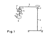
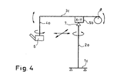
- the first and essential step of the invention is evident in the difference between Fig. 1 and Fig. 4.
- the X-Y displacement unit was 5 immediately above the microscope 6 on one Microscope holder 4 attached or has divided the microscope holder 4 so that its lower part was carried by the X-Y shift unit 5 and the microscope 6 recorded while the upper part carried the X-Y displacement unit 5.
- On Movement of the X-Y displacement unit thus caused an adjustment of the two Parts of the microscope holder 4 in the X-Y direction to each other.
- the microscope holder 4 was conventionally held by a tripod support 3, which on a Swivel and / or pivot bearing 7 was held pivotably and / or rotatably.
- the Camp 7 is only indicated symbolically.
- the structure according to the invention according to FIG. 4 is only in this regard further developed that for weight compensation purposes the tripod support 3c is extended beyond the longitudinal axis of the tripod stand 2a to at his free end to accommodate a counterweight 8. Not shown in detail, however those skilled in the art are familiar with measures for adjusting the Balance weight 8 for optimal weight balance for the microscope 6.
- the structures according to FIG. 4 the weight of the X-Y displacement unit 5b itself no longer be balanced.
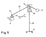
- FIG. 5 An alternative to the invention 4 leads to Construction according to FIG. 5.
- the two tripod support parts 3d pivotable to each other.
- they are in a swivel table and / or pivot bearing 7a, which - as not closer shown - a gear or the like. has, which causes the two parts of the tripod support 3d depending on each other in the opposite Be pivoted in the direction.
- the gear or the like. is designed so that in the static state, i.e. if the tripod support 3d is not pivoted, he the load balancing moments from microscope 6 to balance weight 8 transfers.
- the pivotability of the tripod stand parts to each other allows to keep the overall focus of the tripod low, because in the Usually both the microscope and the balance weight are lower than that highest point of the tripod stand 2.
- the structure according to FIG. 5 is not Tripod support 3 but the tripod stand 2b for receiving the X-Y displacement unit 5b interrupted. The location of this interruption will change constructive measures optimally chosen. Because the displacement paths in the X-Y direction with an X-Y displacement unit, usually only in the millimeter range change, the displacement in the area of the tripod stand 2 is harmless and does not lead to disturbing tilting moments.
- All X-Y displacement units shown can preferably also be uncoupled, see above that X-Y adjustments can also be made manually.
- a computer (not shown in more detail) is used in conjunction with suitable sensor elements to detect the respective position of the microscope in relation to the object or to a patient and to convert the XY command values so that the adjustment movement carried out, for example, in the XY coordinate system of the object or patients or in the coordinate system of the microscope; regardless of how the microscope is pivoted in space.
Landscapes
- Physics & Mathematics (AREA)
- General Physics & Mathematics (AREA)
- Optics & Photonics (AREA)
- Health & Medical Sciences (AREA)
- General Health & Medical Sciences (AREA)
- Surgery (AREA)
- Chemical & Material Sciences (AREA)
- Analytical Chemistry (AREA)
- Microscoopes, Condenser (AREA)
Applications Claiming Priority (3)
| Application Number | Priority Date | Filing Date | Title |
|---|---|---|---|
| CH162098 | 1998-07-31 | ||
| CH162098 | 1998-07-31 | ||
| PCT/EP1999/005448 WO2000008508A1 (de) | 1998-07-31 | 1999-07-30 | Operationsmikroskop-statik für x-y-verschiebung |
Publications (2)
| Publication Number | Publication Date |
|---|---|
| EP1101139A1 EP1101139A1 (de) | 2001-05-23 |
| EP1101139B1 true EP1101139B1 (de) | 2004-12-15 |
Family
ID=4214708
Family Applications (1)
| Application Number | Title | Priority Date | Filing Date |
|---|---|---|---|
| EP99938378A Expired - Lifetime EP1101139B1 (de) | 1998-07-31 | 1999-07-30 | Operationsmikroskop-stativ für x-y-verschiebung |
Country Status (5)
| Country | Link |
|---|---|
| US (1) | US6532108B1 (enExample) |
| EP (1) | EP1101139B1 (enExample) |
| JP (1) | JP4550997B2 (enExample) |
| DE (1) | DE59911285D1 (enExample) |
| WO (1) | WO2000008508A1 (enExample) |
Families Citing this family (13)
| Publication number | Priority date | Publication date | Assignee | Title |
|---|---|---|---|---|
| EP1193438B1 (de) * | 2000-09-28 | 2006-11-15 | Leica Microsystems Schweiz AG | Stativ |
| DE10123166A1 (de) * | 2001-03-31 | 2002-10-10 | Leica Microsystems | Stativ. insbesondere für ein Operationsmikroskop |
| DE10133018A1 (de) | 2001-07-06 | 2003-01-16 | Leica Mikroskopie Systeme Ag H | Stativ |
| JP4326230B2 (ja) * | 2003-01-30 | 2009-09-02 | 株式会社トプコン | 手術用顕微鏡支持装置 |
| DE10353961B4 (de) * | 2003-11-19 | 2005-09-22 | Carl Zeiss | Mikroskopiesystem und Verfahren zum Steuern eines Mikroskopiesystems |
| DE102006044469B4 (de) * | 2006-08-31 | 2019-12-24 | Leica Instruments (Singapore) Pte. Ltd. | Einrichtung zur vibrationsfreien Führung einer Spindel in einem Stativ eines Operationsmikroskops |
| ES2342813B2 (es) * | 2008-12-03 | 2011-05-18 | Carlos Ruiz Lapuente | Quirofano de flujo laminar. |
| US20140107634A1 (en) * | 2011-06-27 | 2014-04-17 | Wavelight Gmbh | Apparatus and method for eye surgery |
| KR101667529B1 (ko) * | 2012-04-30 | 2016-10-28 | 주식회사 고영테크놀러지 | 수술용 로봇 |
| EP3140691A4 (en) * | 2014-05-05 | 2018-01-03 | Health Research, Inc. | Clinical intravital microscope |
| WO2020008652A1 (ja) * | 2018-07-06 | 2020-01-09 | 株式会社ニコン | 支持装置及び手術支援システム |
| US12313832B2 (en) * | 2021-02-07 | 2025-05-27 | Sam Powdrill | Three-axis actuator for a portable microscope |
| DE102022105921A1 (de) * | 2022-03-14 | 2023-09-14 | Carl Zeiss Meditec Ag | Bodenstativ und Vorrichtung zur optischen Erfassung mit einem solchen |
Family Cites Families (18)
| Publication number | Priority date | Publication date | Assignee | Title |
|---|---|---|---|---|
| CH482439A (de) * | 1968-02-20 | 1969-12-15 | Contraves Ag | Beobachtungseinrichtung |
| JPS6013102U (ja) * | 1983-07-04 | 1985-01-29 | 長田電機工業株式会社 | 無影灯駆動機構 |
| US4741607A (en) * | 1986-03-17 | 1988-05-03 | Contraves Ag | Supporting device for an optical observation instrument |
| JP3021561B2 (ja) * | 1989-10-16 | 2000-03-15 | オリンパス光学工業株式会社 | 観察点座標表示機能を有する手術用顕微鏡装置 |
| US5345538A (en) * | 1992-01-27 | 1994-09-06 | Krishna Narayannan | Voice activated control apparatus |
| DE4202922A1 (de) * | 1992-02-01 | 1993-08-05 | Zeiss Carl Fa | Motorisches stativ |
| CH687108A5 (de) * | 1992-12-24 | 1996-09-13 | Anschuetz & Co Gmbh | Bildstabilisierungseinrichtung. |
| JP3321271B2 (ja) * | 1993-03-11 | 2002-09-03 | オリンパス光学工業株式会社 | 手術用顕微鏡 |
| JP3537155B2 (ja) * | 1993-05-07 | 2004-06-14 | オリンパス株式会社 | 手術用顕微鏡 |
| DE4416178B4 (de) * | 1993-05-07 | 2007-11-08 | Olympus Optical Co., Ltd. | Chirurgisches Mikroskop |
| DE4320443C2 (de) | 1993-06-21 | 2001-08-02 | Zeiss Carl | Ausbalancierbares Stativ |
| JPH0759796A (ja) * | 1993-08-31 | 1995-03-07 | Topcon Corp | 手術用顕微鏡俯仰装置 |
| JPH07168100A (ja) * | 1993-11-18 | 1995-07-04 | Nikon Corp | 光学機器 |
| DE4412605B4 (de) * | 1994-04-13 | 2005-10-20 | Zeiss Carl | Verfahren zum Betrieb eines stereotaktischen Adapters |
| JPH08173450A (ja) * | 1994-12-22 | 1996-07-09 | Olympus Optical Co Ltd | 手術用顕微鏡装置 |
| US5713545A (en) * | 1995-12-13 | 1998-02-03 | Mitaka Kohki Co. Ltd. | Stand apparatus for medical optical equipments |
| JP2781164B2 (ja) * | 1995-12-28 | 1998-07-30 | 三鷹光器株式会社 | 医療用スタンド装置のオートバランス構造 |
| US5818638A (en) * | 1996-11-27 | 1998-10-06 | Mitaka Kohki Co. Ltd. | Deflection compensating structure for medical stand apparatus |
-
1999
- 1999-07-30 EP EP99938378A patent/EP1101139B1/de not_active Expired - Lifetime
- 1999-07-30 DE DE59911285T patent/DE59911285D1/de not_active Expired - Lifetime
- 1999-07-30 JP JP2000564084A patent/JP4550997B2/ja not_active Expired - Fee Related
- 1999-07-30 WO PCT/EP1999/005448 patent/WO2000008508A1/de not_active Ceased
- 1999-07-30 US US09/744,371 patent/US6532108B1/en not_active Expired - Fee Related
Also Published As
| Publication number | Publication date |
|---|---|
| WO2000008508A1 (de) | 2000-02-17 |
| EP1101139A1 (de) | 2001-05-23 |
| JP4550997B2 (ja) | 2010-09-22 |
| DE59911285D1 (de) | 2005-01-20 |
| JP2002522134A (ja) | 2002-07-23 |
| US6532108B1 (en) | 2003-03-11 |
Similar Documents
| Publication | Publication Date | Title |
|---|---|---|
| EP1067419B1 (de) | Deckenstativ | |
| EP1101139B1 (de) | Operationsmikroskop-stativ für x-y-verschiebung | |
| DE102008011639A1 (de) | Stativ, insbesondere für ein Operations-Mikroskop | |
| DE69330051T2 (de) | Ständer eines optischen instruments für mezinische anwendung | |
| DE10133018A1 (de) | Stativ | |
| EP1207334B1 (de) | Stativ | |
| DE10350531A1 (de) | Verfahren zur Steuerung eines Tisches und Tischsystem | |
| EP0433426A1 (de) | Mit zusatzvorrichtungen ausgestattetes stativ für die halterung eines frei positionierbaren gerätes. | |
| DE20114343U1 (de) | Stativ | |
| DE102011119813A1 (de) | Stativ für ein Operationsmikroskop | |
| EP3217939A1 (de) | Abstützgelenk für einen tragarm einer medizintechnischen stativvorrichtung | |
| EP1336885B1 (de) | Mikrochirurgisches Mikroskopsystem | |
| EP1336884B1 (de) | Mikrochirurgisches Mikroskopsystem | |
| DE4128669A1 (de) | Dreidimensional verstellbare deckenaufhaengung fuer operationsmikroskope | |
| EP1324094B1 (de) | Stativ mit Operationsmikroskop | |
| DE7315186U (de) | Verstellbares stativ fuer ein optisches beobachtungsgeraet, insbesondere ein binokularmikroskop | |
| EP1251380A2 (de) | Stativ, insbesondere für ein Operationsmikroskop | |
| DE69201691T2 (de) | Mobiles Röntgengerät. | |
| DE102011119814A1 (de) | Stativ | |
| WO1998052484A1 (de) | Stativ, insbesondere für ein operationsmikroskop | |
| EP0061153A1 (de) | Industrieroboter | |
| DE102010010131B4 (de) | Stativ für ein Mikroskop, insbesondere für ein Operationsmikroskop, und Verwendung eines solchen Stativs | |
| DE202021102746U1 (de) | Haltevorrichtung für eine medizinische Einrichtung sowie medizinische Vorrichtung umfassend die Haltevorrichtung | |
| DE102005031494A1 (de) | Stativ mit mindestens acht Bewegungsfreiheitsgraden | |
| DE3425650A1 (de) | Roentgenuntersuchungsgeraet mit einem c- oder u-foermigen traeger fuer den roentgenstrahler und die bildaufnahmevorrichtung |
Legal Events
| Date | Code | Title | Description |
|---|---|---|---|
| PUAI | Public reference made under article 153(3) epc to a published international application that has entered the european phase |
Free format text: ORIGINAL CODE: 0009012 |
|
| 17P | Request for examination filed |
Effective date: 20010104 |
|
| AK | Designated contracting states |
Kind code of ref document: A1 Designated state(s): AT BE CH CY DE DK ES FI FR GB GR IE IT LI LU MC NL PT SE |
|
| 17Q | First examination report despatched |
Effective date: 20010620 |
|
| RAP1 | Party data changed (applicant data changed or rights of an application transferred) |
Owner name: LEICA MICROSYSTEMS (SCHWEIZ) AG |
|
| GRAP | Despatch of communication of intention to grant a patent |
Free format text: ORIGINAL CODE: EPIDOSNIGR1 |
|
| RBV | Designated contracting states (corrected) |
Designated state(s): CH DE FR GB LI |
|
| GRAS | Grant fee paid |
Free format text: ORIGINAL CODE: EPIDOSNIGR3 |
|
| GRAA | (expected) grant |
Free format text: ORIGINAL CODE: 0009210 |
|
| AK | Designated contracting states |
Kind code of ref document: B1 Designated state(s): CH DE FR GB LI |
|
| REG | Reference to a national code |
Ref country code: GB Ref legal event code: FG4D Free format text: NOT ENGLISH Ref country code: CH Ref legal event code: EP |
|
| REG | Reference to a national code |
Ref country code: IE Ref legal event code: FG4D Free format text: GERMAN |
|
| REF | Corresponds to: |
Ref document number: 59911285 Country of ref document: DE Date of ref document: 20050120 Kind code of ref document: P |
|
| REG | Reference to a national code |
Ref country code: CH Ref legal event code: NV Representative=s name: ROSENICH PAUL; GISLER CHRISTIAN PATENTBUERO PAUL R |
|
| GBT | Gb: translation of ep patent filed (gb section 77(6)(a)/1977) |
Effective date: 20050504 |
|
| PLBE | No opposition filed within time limit |
Free format text: ORIGINAL CODE: 0009261 |
|
| STAA | Information on the status of an ep patent application or granted ep patent |
Free format text: STATUS: NO OPPOSITION FILED WITHIN TIME LIMIT |
|
| 26N | No opposition filed |
Effective date: 20050916 |
|
| ET | Fr: translation filed | ||
| PGFP | Annual fee paid to national office [announced via postgrant information from national office to epo] |
Ref country code: CH Payment date: 20080715 Year of fee payment: 10 |
|
| PGFP | Annual fee paid to national office [announced via postgrant information from national office to epo] |
Ref country code: FR Payment date: 20080715 Year of fee payment: 10 |
|
| PGFP | Annual fee paid to national office [announced via postgrant information from national office to epo] |
Ref country code: GB Payment date: 20080722 Year of fee payment: 10 |
|
| REG | Reference to a national code |
Ref country code: CH Ref legal event code: PL |
|
| GBPC | Gb: european patent ceased through non-payment of renewal fee |
Effective date: 20090730 |
|
| REG | Reference to a national code |
Ref country code: FR Ref legal event code: ST Effective date: 20100331 |
|
| PG25 | Lapsed in a contracting state [announced via postgrant information from national office to epo] |
Ref country code: LI Free format text: LAPSE BECAUSE OF NON-PAYMENT OF DUE FEES Effective date: 20090731 Ref country code: FR Free format text: LAPSE BECAUSE OF NON-PAYMENT OF DUE FEES Effective date: 20090731 Ref country code: CH Free format text: LAPSE BECAUSE OF NON-PAYMENT OF DUE FEES Effective date: 20090731 |
|
| PG25 | Lapsed in a contracting state [announced via postgrant information from national office to epo] |
Ref country code: GB Free format text: LAPSE BECAUSE OF NON-PAYMENT OF DUE FEES Effective date: 20090730 |
|
| PGFP | Annual fee paid to national office [announced via postgrant information from national office to epo] |
Ref country code: DE Payment date: 20130722 Year of fee payment: 15 |
|
| REG | Reference to a national code |
Ref country code: DE Ref legal event code: R119 Ref document number: 59911285 Country of ref document: DE |
|
| PG25 | Lapsed in a contracting state [announced via postgrant information from national office to epo] |
Ref country code: DE Free format text: LAPSE BECAUSE OF NON-PAYMENT OF DUE FEES Effective date: 20150203 |
|
| REG | Reference to a national code |
Ref country code: DE Ref legal event code: R119 Ref document number: 59911285 Country of ref document: DE Effective date: 20150203 |