EP1099862B1 - Ensemble de tuyaux et tiges filetées - Google Patents
Ensemble de tuyaux et tiges filetées Download PDFInfo
- Publication number
- EP1099862B1 EP1099862B1 EP00120814A EP00120814A EP1099862B1 EP 1099862 B1 EP1099862 B1 EP 1099862B1 EP 00120814 A EP00120814 A EP 00120814A EP 00120814 A EP00120814 A EP 00120814A EP 1099862 B1 EP1099862 B1 EP 1099862B1
- Authority
- EP
- European Patent Office
- Prior art keywords
- profile
- threaded rod
- pipe
- approx
- kit according
- Prior art date
- Legal status (The legal status is an assumption and is not a legal conclusion. Google has not performed a legal analysis and makes no representation as to the accuracy of the status listed.)
- Expired - Lifetime
Links
Images


Classifications
-
- F—MECHANICAL ENGINEERING; LIGHTING; HEATING; WEAPONS; BLASTING
- F16—ENGINEERING ELEMENTS AND UNITS; GENERAL MEASURES FOR PRODUCING AND MAINTAINING EFFECTIVE FUNCTIONING OF MACHINES OR INSTALLATIONS; THERMAL INSULATION IN GENERAL
- F16B—DEVICES FOR FASTENING OR SECURING CONSTRUCTIONAL ELEMENTS OR MACHINE PARTS TOGETHER, e.g. NAILS, BOLTS, CIRCLIPS, CLAMPS, CLIPS OR WEDGES; JOINTS OR JOINTING
- F16B7/00—Connections of rods or tubes, e.g. of non-circular section, mutually, including resilient connections
- F16B7/18—Connections of rods or tubes, e.g. of non-circular section, mutually, including resilient connections using screw-thread elements
-
- Y—GENERAL TAGGING OF NEW TECHNOLOGICAL DEVELOPMENTS; GENERAL TAGGING OF CROSS-SECTIONAL TECHNOLOGIES SPANNING OVER SEVERAL SECTIONS OF THE IPC; TECHNICAL SUBJECTS COVERED BY FORMER USPC CROSS-REFERENCE ART COLLECTIONS [XRACs] AND DIGESTS
- Y10—TECHNICAL SUBJECTS COVERED BY FORMER USPC
- Y10T—TECHNICAL SUBJECTS COVERED BY FORMER US CLASSIFICATION
- Y10T403/00—Joints and connections
- Y10T403/32—Articulated members
- Y10T403/32254—Lockable at fixed position
- Y10T403/32467—Telescoping members
-
- Y—GENERAL TAGGING OF NEW TECHNOLOGICAL DEVELOPMENTS; GENERAL TAGGING OF CROSS-SECTIONAL TECHNOLOGIES SPANNING OVER SEVERAL SECTIONS OF THE IPC; TECHNICAL SUBJECTS COVERED BY FORMER USPC CROSS-REFERENCE ART COLLECTIONS [XRACs] AND DIGESTS
- Y10—TECHNICAL SUBJECTS COVERED BY FORMER USPC
- Y10T—TECHNICAL SUBJECTS COVERED BY FORMER US CLASSIFICATION
- Y10T403/00—Joints and connections
- Y10T403/70—Interfitted members
Definitions
- the invention relates to a kit of threaded rods and tubes.
- Threaded rods and pipes are widely used for construction and handicraft work.
- the application areas are almost unlimited. Furniture, shelving constructions, simple technical constructions up to more complicated devices are manufactured.
- the use in the household, e.g. as a curtain rod, hinge or bracket for tabletops, etc. is conceivable.
- the object of the invention is to provide a kit of threaded rods and tubes, in which many possible combinations of threaded rods with pipes or pipes are possible with each other.
- a particularly advantageous kit consisting of threaded rods and tubes includes a first group of metric threaded rods according to the standard DIN 13 T 1 in gradation M8, M12, M16 and M20, each threaded rod is associated with a tube, which is about a 3.5 mm greater external dimension than the nominal size of the associated threaded rod.
- the combination allows, among other things, the telescopic nesting of all pipes contained in the kit.
- Another great advantage of this combination is that it is only standard commercial threaded rods with common nominal diameters. As a result, the combination variety is further increased, since commercial nuts and other threaded attachments can be combined with the kit.
- a particularly advantageous embodiment of the invention provides that the tubes belonging to the threaded rods with the graduation M8, M12, M16, M20, have a tube wall thickness of 1.5 mm.
- the distance between the threaded rod and inner tube wall of belonging to a threaded rod tube is then approximately always the same, which always gives the same clearance of the clearance when used in the combination threaded rod tube. Also, the clearance of the threaded rod - pipe - assignments remains unchanged.
- the first group of metric threaded rods with the dimension M5.
- the tube associated with this threaded rod has an outer dimension of about 7.5 mm and the tube wall is formed in a thickness of about 1 mm. This extension makes it possible to use the kit for applications where relatively small nominal diameter threads are needed. The tube associated with this threaded rod can be easily inserted into the next larger tube of this group.
- each of these threaded rods is associated with a tube having an outer dimension about 5.5 mm larger than the nominal size of the associated threaded rod, wherein the tube wall is formed in a tube thickness of about 2.4 mm.
- This extension makes it possible to use the kit for applications where relatively large nominal diameter threads are needed.
- the tubes associated with these threaded rods can be easily combined with the tubes of the first group.
- Another particularly advantageous kit consists of threaded rods and tubes, which includes a second group of metric threaded rods according to the standard DIN 13 T 1 in gradation M6, M10, M14 and M18, each threaded rod is associated with a tube, which is a by about 3 , 5 mm larger external dimension than the nominal size of the associated threaded rod.
- This combination also allows, among other things, the telescoping nesting of all tubes contained in the kit.
- Another great advantage of this combination is The fact that the threaded rods used in this kit are also standardized commercial threaded rods with standardized nominal diameters. As a result, the combination variety is further increased, since commercial nuts and other popular threaded attachments can be combined.
- a particularly advantageous embodiment of the invention provides that the tubes belonging to the threaded rods with the graduation M6, M10, M14, M18, have a tube wall thickness of 1.5 mm.
- the distance between the threaded rod and inner tube wall of belonging to a threaded rod tube is then approximately the same, which always gives the same clearance when used in the combination threaded rod tube. The clearance fit when using pipe combinations remains unchanged.
- the threaded rod with the nominal size M22 a tube with an outer dimension of about 26.5 mm and the threaded rod with the nominal size M27 is assigned a pipe with an external dimension of about 32.5 mm.
- the pipe wall thickness of the pipe with the outer dimension of 26.5 mm is about 1.9 mm and the pipe wall thickness of the pipe with the outer dimension of 32.5 mm measures about 2.4 mm.
- a further advantageous embodiment of the invention provides that in a kit of threaded rods and tubes each threaded rod is associated with a square profile tube which surrounds the threaded rod at a distance, and whose outer sides shorter than the inner sides of the square tube profile next larger threaded rod-square tube assignment.
- Pipes with a square cross-section can be ideally used, for example, as guide rails, wherein they can be extended in length by the possibility of telescopically nesting within a kit as desired.
- the combination of threaded rod and tube for many applications such as shelving is conceivable.
- all the advantages described for round tubes also apply to tubes with a square profile. It opens up the possibility due to the similarity of the dimensions of round tube and square tube, now also combine this in addition, so that, for example, a round tube with internal threaded rod in a tube with square profile can be inserted.
- the kit consists of a first group of threaded rods, which have metric dimensions, in the gradation M8, M12, M16 and M20, each threaded rod is associated with a square profile tube, wherein the outer distance of the opposite Sides about 3.5 mm more than the nominal size of the associated threaded rod measures.
- a particularly advantageous embodiment of the invention provides that the pipe wall of the tubes belonging to the first group of threaded rods having a square profile has a tube wall thickness of about 1.5 mm.
- the distance between the threaded rod and the center points of the sides is always the same, whereby the clearance always has the same play when used in the combination threaded rod tube.
- the clearance fit when using pipe combinations remains unchanged.
- the first group of threaded rods in addition to a threaded rod with the metric dimension M5, wherein the threaded rod is a tube with square Assigned profile, wherein the outer distance of the opposite sides is about 7.5 mm and the pipe wall is formed in a thickness of about 1 mm.
- the first group of threaded rods is extended by threaded rods of nominal size M24 and M30, each with a square profile tube, the distance between the outer sides being approximately 5.5 mm more than the nominal size associated threaded rod measures, and the pipe wall is formed in a tube thickness of about 2.4 mm.
- the kit consists of a second group of threaded rods having metric dimensions in the increments M6, M10, M14 and M18, wherein each threaded rod is associated with a square profile tube and the outer distance of the opposite sides about 3.5 mm more than the nominal size of the associated threaded rod.
- a further advantageous embodiment provides that the tube wall of the square-profile tubes belonging to the second group of threaded rods has a tube wall thickness of approximately 1.5 mm.
- the second group of threaded rods is extended by threaded rods having a nominal dimension of M22 and M27, wherein the threaded rod of nominal size M22 is associated with a square profile tube in which the outer distance of the opposite sides is about 26.5 mm , and the threaded rod of nominal size M27 is associated with a square profile tube in which the outer distance of the opposite sides measures about 32.5 mm.
- the pipe with a square profile belonging to the threaded rod with the nominal metric diameter M22 has a pipe wall thickness of approximately 1.9 mm and the pipe belonging to the threaded rod with the nominal metric diameter M27 has a pipe wall thickness of approximately 2.4 mm.
- each threaded rod is assigned a tube with a rectangular profile, which encloses the threaded rod with distance and whose outer sides are shorter than the corresponding inner sides of the rectangular tube of the next larger threaded rod-tube assignment.
- round tubes can now be combined with rectangular tubes and square tubes.
- a particular advantage of the extension is that the square tubes can be ideally performed in the rectangular tubes, since the length of the longer profile sides of the rectangular tubes corresponds to an integer multiple of the outer distance of the opposite longer profile pages.
- the kit consists of a first group of threaded rods having metric dimensions, in the gradation M8, M12, M16, M20, each threaded rod is associated with a tube with a rectangular profile, wherein the outer distance of the opposite longer profile sides about 3.5 mm more than the nominal size of the associated threaded rod measures and the length of the longer profile side corresponds to at least a multiple of the outer distance of the longer profile sides.
- the tube wall of the tubes of rectangular profile belonging to the first group of threaded rods has a tube wall thickness of about 1.5 mm.
- the first group of threaded rods is additionally extended by a threaded rod with the metric dimension M5, wherein the threaded rod is associated with a tube with a rectangular profile, wherein the outer distance of the opposite longer profile sides is about 7.5 mm and the length of the longer profile side corresponds to at least a multiple of the outer distance of the longer profile sides and the pipe wall is formed in a thickness of about 1 mm.
- the first group of threaded rods is extended by threaded rods with a nominal size of M24 and M30, to each of which a tube having a rectangular profile is assigned, wherein the outer spacing of the opposite longer profile sides is approximately 5.5 mm more than that Nominal dimension of the associated threaded rod measures and the length of the longer profile side corresponds to at least a multiple of the outer distance of the longer profile sides, wherein the tube wall is formed in a tube thickness of about 2.4 mm.
- the kit consists of a second group of threaded rods having metric dimensions in the gradation M6, M10, M14 and M18, wherein the outer distance of the opposite longer profile sides about 3.5 mm more than the nominal size of associated threaded rod measures, and that the length of the longer profile side corresponds to at least a multiple of the outer distance of the longer profile sides.
- the tube wall of the tubes belonging to the second group of threaded rods with a rectangular profile has a tube wall thickness of about 1.5 mm.
- the combination variety is further enhanced when the second group of threaded rods is extended by threaded rods of nominal size M22 and M27, with the threaded rod of nominal size M22 being associated with a rectangular profile tube in which the outer distance of the opposed longer profile sides is about 26 , 5 mm, and the threaded rod of nominal size M27 is associated with a rectangular profile tube in which the outer distance of the opposite longer profile sides measures approximately 32.5 mm and the length of the longer profile side is at least a multiple of the outer distance of the longer profile sides equivalent.
- the tube of rectangular profile belonging to the threaded rod with the nominal metric diameter M22 has a tube wall thickness of approximately 1.9 mm and the tube with rectangular profile belonging to the threaded rod with the nominal metric diameter M27 has a tube wall thickness of approximately 2.4 mm ,
- a particularly advantageous kit provides that each threaded rod is associated with a U-profile, which surrounds the threaded rod on three sides with distance and whose outer sides are shorter than the corresponding inner sides of the U-profile of the next larger threaded rod U-profile assignment ,
- round tubes can now be combined with rectangular tubes, square tubes and U-profiles.
- Particularly advantageous in the extension of the described tubes with U-profile is that the square tubes can be performed ideally in the U-profiles, since the length of the longer profile sides of the U-profile at least an integer multiple of the length of the shorter sides and thus at least an integer multiple of the length of the associated square tube corresponds. It is also possible to combine rectangular tubes with U-profiles, as the longer profile side of the U-profile in their Dimensions behaves just like the longer profile sides of the associated tube with a rectangular profile.
- the kit consists of a first group of threaded rods having metric dimensions in the increments M8, M12, M16 and M20, wherein each threaded rod is associated with a U-profile, wherein the shorter profile sides about 3 , Measure 5 mm more than the nominal size of the associated threaded rod and the length of the longer profile side shall be at least a multiple of the length of the shorter profile sides.
- the wall of the U-profile belonging to the first group of threaded rods has a thickness of about 1.5 mm.
- the first group of threaded rods is additionally extended by a threaded rod with the metric dimension M5, wherein the threaded rod is associated with a U-profile, in which the length of the shorter profile sides is about 7.5 mm and in which the length of the longer profile side corresponds to at least a multiple of the length of the shorter profile sides and the wall is formed in a thickness of about 1 mm.
- the first group of threaded rods is extended by threaded rods with a nominal size of M24 and M30, each of which is assigned a U-profile, with the shorter profile sides measuring approximately 5.5 mm more than the nominal size of the associated threaded rod and wherein the length of the longer profile side corresponds to at least a multiple of the length of the shorter profile sides, wherein the wall is formed in a thickness of about 2.4 mm.
- the kit consists of a second group of threaded rods having metric dimensions in the gradation M6, M10, M14 and M18, each threaded rod is associated with a tube with a U-profile, in which the shorter profile pages about Measure 3.5 mm more than the nominal dimension of the associated threaded rod and the length of the longer profile side is at least a multiple of the length of the shorter profile sides.
- the wall of the U-profiles belonging to the second group of threaded rods has a thickness of approximately 1.5 mm.
- the variety of combinations is increased by the second group of threaded rods is extended by threaded rods with a nominal size of M22 and M27, wherein the threaded rod with the nominal size M22 is assigned a U-profile, in which the length of the shorter profile sides is about 26.5 mm and the threaded rod of nominal size M27 is associated with a U-profile in which the length of the shorter profile sides measures approximately 32.5 mm and the length of the longer profile side corresponds to at least a multiple of the length of the shorter profile sides.
- the U-profile belonging to the threaded rod with the metric nominal diameter M22 has a wall thickness of about 1.9 mm and that the U-profile belonging to the threaded rod with the nominal metric diameter M27 has a wall thickness of about 2.4 mm ,
- the kit comprises tubes with integrally formed webs, wherein the web is arranged in particular tangentially.
- This construction is ideal for the construction of door hinges. It is conceivable to provide the webs with holes for screws, so that plates, doors or the like can be mounted on the web in a simple manner.
- the plate is to be fastened at the middle rather centrally, another embodiment of the invention is suitable in which the kit has tubes with integrally formed webs, wherein the web is orthogonal to the radius.
- the kit U-profiles and / or tubes with square or rectangular profile with integrally formed webs. Through the webs arise new mounting options and bearing surfaces. The functionality of the kit is increased.
- a reduction tube is inserted between the threaded rod and pipe with integrally formed web. It is particularly advantageous if the reduction tube is made of e.g. Plastic is formed. The sliding effect is thereby significantly increased.
- all tubes or U-profiles of the kit in two groups of tubes telescopically formed into one another. This makes the extension of pipes easier and there are new constructive possibilities.
- the invention includes a method for kink-free bending of pipes.
- Pipes can not bend without special bending devices kink-free.
- the tube assigned to a specific threaded rod is pushed over the threaded rod. Then the pipe is bent without bending by bending the threaded rod.
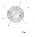
- Figure 1 shows a threaded rod 1 with metric nominal size, which is associated with a tube 2, the inner diameter of the threaded rod wrapped at a distance A and the outer diameter is smaller than the inner diameter of the tube 3 of the next larger threaded rod-tube assignment.
- the distance A between the threaded rod 1 and the inner wall 4 of the tube 2 is about 0.25 mm for both groups of threaded rods in a central arrangement of M5 to M20, from about M20 about 0.35 mm.
- the tube wall thickness of the tube for the M5 threaded rod is about 1 mm
- the tube wall thickness of the tubes for the threaded rods M6 to M20 is about 1.5 mm
- the tube wall thickness of the tube for the threaded rod M22 about 1.9 mm
- the tube wall thickness of the tubes for the Threaded rods M24 to M30 is about 2.4 mm.
- the game 5 on both sides with a centric arrangement between the tubes 2 and 3 is in the tubes for the threaded rods to M20 about 0.5 mm, from M22 about 0.6 mm.
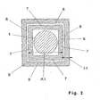
- FIG. 2 shows a threaded rod 1, which is associated with a tube with a square profile 6, which surrounds the threaded rod 1 at a distance.
- the outer sides 7 of the tube with square profile 6 are shorter than the inner sides 8 of the next larger square tube 9.
- the distance A1 of two opposite sides 7 and the wall thickness 11 behave like the outer diameter or as the tube wall thickness of the corresponding round tubes.
- a threaded rod with a metric nominal size of M10 is assigned a round tube with an outer diameter of about 13.5 mm.
- the opposite sides of the corresponding tube with square profile thus have a distance A1 of about 13.5 mm.
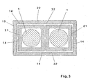
- FIG 3 two threaded rods are shown, which have metric dimensions and each of which a tube with a square profile 21 is assigned, which surrounds the threaded rods at a distance.
- This arrangement is enveloped by a tube 22 of rectangular cross-section, wherein the length of the longer, inner profile sides 32 at least an integer multiple of the corresponding Tubes 21 corresponds with square profile.
- a threaded rod with a nominal size of M10 is assigned a square profile tube.
- the length of the outer profile side of the tube is about 13.5 mm as described above.
- the length of the longer, inner profile pages 32 is thus about 13.5 mm, 27 mm, 40.5 mm etc.
- the length of the longer, inner base side 31 corresponds to at least an integer multiple of the corresponding tubes with a square profile.
- a threaded rod with a nominal size of M10 is assigned a square profile tube.
- the length of the outer profile side of the tube is about 13.5 mm as described above.
- the length of the longer inner base side 31 is thus about 13.5 mm, 27 mm, 40.5 mm etc.
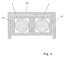
- FIG. 5 shows two threaded rods 1, to each of which a tube with a square cross-section 21 is associated, which encloses the respective threaded rod at a distance.
- a U-profile 22 is arranged around the two tubes with a square profile. The length of the inner, longer side of the U-profile is approximately twice the length of a corresponding tube with square profile 21st
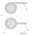
- Figure 6 shows two threaded rods 23 and 24.
- Each of these threaded rods 23 and 24 is associated with a tube with molded web which wraps the threaded rods 23 and 24 with distance.
- the web 25 is arranged tangentially.
- the web 26 is orthogonal to the radius of the tube.
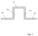
- FIG. 7 shows a further embodiment of the tubes contained in the kit.
- a U-profile 27 is shown with integrally formed webs 28.
- the webs are in the right Winkei to the ends of the shorter profile pages 29th
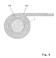
- Figure 8 shows a reduction tube 34 which is inserted to increase the sliding action between the threaded rod 1 and tube with integrally molded web 33.
- FIG. 9 shows a tube 35 pushed onto a threaded rod 26 and bent with it.
Landscapes
- Engineering & Computer Science (AREA)
- General Engineering & Computer Science (AREA)
- Mechanical Engineering (AREA)
- Packaging Of Annular Or Rod-Shaped Articles, Wearing Apparel, Cassettes, Or The Like (AREA)
- Mutual Connection Of Rods And Tubes (AREA)
Claims (22)
- Kit composé d'au moins deux tiges filetées normalisées et d'au moins deux tubes, caractérisé en ce qu'un premier tube (2) enveloppant la première tige filetée à distance est associé à la première tige filetée (1) et en ce que le premier tube peut être enveloppé avec un jeu (5) par un deuxième tube (3) qui enveloppe à distance la deuxième tige de taille immédiatement supérieure, les tiges filetées étant prélevées dans un groupe présentant des dimensions métriques dans la gradation M5 et M8 ou M8 et M12 ou M12 et M16 ou M16 et M20 ou M20 et M24 ou M24 et M30 ou M6 et M10 ou M16 et M14 ou M 14 et M18 OU M18 et M 22 ou M22 et M 27.
- Kit selon la revendication 1, caractérisé en ce que le tube présente une dimension extérieure supérieure d'environ 3,5 mm à la dimension nominale de la tige filetée correspondante.
- Kit selon la revendication 2, caractérisé en ce que la paroi du tube présente une épaisseur de paroi de tube d'environ 1,5 mm.
- Kit selon l'une quelconque des revendications 2 ou 3, caractérisé en ce qu'un tube présentant une dimension extérieure d'environ 7,5 mm est associé à la tige filetée avec la dimension métrique M5 et en ce que la paroi de tube est conçue avec une épaisseur d'environ 1 mm.
- Kit selon l'une quelconque des revendications 2 à 4, caractérisé en ce que respectivement un tube présentant une dimension extérieure supérieure d'environ 5,5 mm à la valeur nominale de la tige filetée correspondante est associé à la valeur nominale de M24 et M30, la paroi de tube étant conçue dans une épaisseur de tube d'environ 2,4 mm.
- Kit selon l'une quelconque des revendications 1 à 5, caractérisé en ce qu'un tube avec une dimension extérieure d'environ 26,5 mm est associé à la tige filetée de dimension nominale M22 et en ce qu'un tube d'une dimension extérieure d'environ 32,5 mm est associé à la tige filetée de dimension nominale M27 et en ce que le tube d'une dimension extérieure de 26,5 mm présente une épaisseur de paroi de tube d'environ 1,9 mm et en ce que le tube avec une dimension extérieure d'environ 32,5 mm présente une épaisseur de paroi d'environ 2,4 mm.
- Kit selon l'une quelconque des revendications 1 à 6, caractérisé en ce que tube (6) présente un profil quadratique.
- Kit selon l'une quelconque des revendications 1 à 6, caractérisé en ce que le tube présente un profil rectangulaire (12).
- Kit composé d'au moins deux tiges filetées normalisées et d'au moins deux profils en U, caractérisé en ce qu'un premier profil en U (30) qui enveloppe la première tige filetée à distance est associé à la première tige filetée normalisée (1) et en ce que le profil en U peut être enveloppé par un deuxième profil en U qui enveloppe à distance la deuxième tige filetée d'une dimension immédiatement supérieure, les tiges filetées étant prélevées dans un groupe présentant des dimensions métriques dans la gradation M5 et M8 ou M8 et M12 ou M12 et M16 ou M16 et M20 ou M20 et M24 ou M24 et M30 ou M6 et M10 et/ou M10 et M14 et/ou M 14 et M18 OU M18 et M 22 ou M22 et M27.
- Kit selon la revendication 9, caractérisé en ce que sur le profil en U, les côtés les plus courts du profil mesurent environ 3,5 mm de plus que la dimension nominale de la tige filetée correspondante et en ce que la longueur du côté le plus long du profil correspond au moins à un multiple de la longueur des côtés les plus courts du profil.
- Kit selon la revendication 9 ou 10, caractérisé en ce que la paroi des profils en U présente une épaisseur d'environ 1,5 mm.
- Kit selon l'une quelconque des revendications 9 à 11, caractérisé en ce qu'un profil en U sur lequel la longueur des côtés les plus courts du profil est d'environ 7,5 mm et sur lequel la longueur des côtés les plus longs du profil correspond au moins à un multiple des côtés les plus courts du profil est associé à la tige filetée M5 et en ce que la paroi est conçue dans une épaisseur d'environ 1 mm.
- Kit selon l'une quelconque des revendications 9 à 12, caractérisé en ce qu'un profil en U, dont les côtés les plus courts du profil mesurent environ 5,5 mm de plus que la dimension nominale de la tige filetée correspondante et sur lequel la longueur du côté le plus long du profil correspond au moins à un multiple de la longueur des côtés les plus courts du profil est associé aux tiges filetées d'une dimension nominale de M24 et M30, la paroi étant conçue dans une épaisseur d'environ 2,4 mm.
- Kit selon l'une quelconque des revendications 9 à 13, caractérisé en ce que dans la gradation M6, M10, M14 et M18, les côtés les plus courts du profil en U mesurent environ 3,5 mm de plus que la dimension nominale de la tige filetée correspondante et en ce que la longueur du côté le plus long du profil correspond au moins à un multiple de la longueur des côtés les plus courts du profil.
- Kit selon l'une quelconque des revendications 9 à 14, caractérisé en ce qu'un profil en U sur lequel la longueur des côtés les plus courts du profil est d'environ 26,5 mm est associé à la tige filetée avec la dimension nominale M22 et en ce qu'un profil en U sur lequel la longueur des côtés les plus courts du profil mesure environ 32,5 mm est associé à la tige filetée avec la dimension nominale M27 et en ce que la longueur du côté le plus long du profil correspond au moins à un multiple de la longueur des côtés les plus courts du profil.
- Kit selon l'une quelconque des revendications 1 à 15, caractérisé en ce que le profil en U correspondant à la tige filetée avec un diamètre nominal métrique M22 présente une épaisseur de paroi d'environ 1,9 mm et en ce que le profil en U correspondant à la tige filetée avec le diamètre nominal métrique M27 présente une épaisseur de paroi d'environ 2,4 mm.
- Kit selon l'une quelconque des revendications 1 à 16, caractérisé en ce que le kit comporte des profils en U et/ou des tubes avec des nervures (25) formées par moulage, la nervure (25) étant disposée notamment de façon tangentielle.
- Kit selon l'une quelconque des revendications 1 à 17, caractérisé en ce que le kit comporte des profils en U et/ou des tubes avec des nervures (26) formées par moulage, la nervure (26) étant disposée de façon orthogonale.
- Kit selon l'une quelconque des revendications 1 à 18, caractérisé en ce que le kit comporte des profils en U (27) et/ou des tubes avec un profil quadratique ou rectangulaire avec des nervures (28) formées par moulage.
- Kit selon l'une quelconque des revendications 17 ou 18, caractérisé en ce qu'un tube réducteur (34) peut être inséré entre la tige filetée (1) et le tube avec une nervure (33) formée par moulage.
- Kit selon l'une quelconque des revendications 1 à 20, caractérisé en ce que tous les tubes ou profils en U du kit sont conçus de façon à pouvoir être assemblés de façon télescopique les uns dans les autres.
- Procédé de cintrage sans flambage de tubes selon la revendication 1, caractérisé en ce qu'on pousse le tube (35) associé à une certaine tige filetée (36) par-dessus la tige filetée (36) et en ce que par cintrage de la tige filetée (36), on le cintre également sans flambage.
Priority Applications (1)
| Application Number | Priority Date | Filing Date | Title |
|---|---|---|---|
| DE20022715U DE20022715U1 (de) | 1999-11-11 | 2000-09-23 | Profilsystem |
Applications Claiming Priority (2)
| Application Number | Priority Date | Filing Date | Title |
|---|---|---|---|
| DE19954303 | 1999-11-11 | ||
| DE19954303A DE19954303A1 (de) | 1999-11-11 | 1999-11-11 | Profil System |
Publications (4)
| Publication Number | Publication Date |
|---|---|
| EP1099862A2 EP1099862A2 (fr) | 2001-05-16 |
| EP1099862A3 EP1099862A3 (fr) | 2002-01-02 |
| EP1099862B1 true EP1099862B1 (fr) | 2006-08-30 |
| EP1099862B2 EP1099862B2 (fr) | 2010-07-28 |
Family
ID=7928705
Family Applications (1)
| Application Number | Title | Priority Date | Filing Date |
|---|---|---|---|
| EP00120814A Expired - Lifetime EP1099862B2 (fr) | 1999-11-11 | 2000-09-23 | Ensemble de tuyaux et tiges filetées |
Country Status (3)
| Country | Link |
|---|---|
| US (1) | US6575655B1 (fr) |
| EP (1) | EP1099862B2 (fr) |
| DE (2) | DE19954303A1 (fr) |
Families Citing this family (1)
| Publication number | Priority date | Publication date | Assignee | Title |
|---|---|---|---|---|
| CN105927631A (zh) * | 2016-04-28 | 2016-09-07 | 苏州市林氏精密五金标准件制造有限公司 | 一种减震内管 |
Family Cites Families (20)
| Publication number | Priority date | Publication date | Assignee | Title |
|---|---|---|---|---|
| DE6950247U (de) | 1969-12-29 | 1970-06-04 | Effer Sas | Dreiarmiger kranausleger. |
| DE366870C (de) * | 1920-08-12 | 1923-01-12 | Gustav Buchenau | Metallenes, gitterfoermiges Stabwerk |
| US2035488A (en) * | 1932-04-08 | 1936-03-31 | Warren Mcarthur Corp | Metal furniture construction |
| US3004743A (en) * | 1958-09-15 | 1961-10-17 | Harry J Wenger | Music stands |
| DE1627531C3 (de) * | 1967-09-01 | 1974-08-22 | Arog Armaturen + Apparate + Roehren Gmbh, 4630 Bochum-Gerthe | Einrichtung zur Herstellung von Mantelrohrbogen |
| FR2410162A1 (fr) * | 1977-11-23 | 1979-06-22 | Nasi Cesar | Dispositif destine a assurer l'assemblage reciproque d'elements de preference metalliques |
| IT8130626U1 (it) * | 1981-02-26 | 1982-08-26 | Italmanubri Spa | Canotto reggisella regolabile riveduto e corretto |
| DE3148210A1 (de) * | 1981-12-05 | 1983-06-09 | Henschel Flugzeug-Werke Ag, 3500 Kassel | Schutzeinrichtung fuer mit formbarem fuellstoff zu biegende hohlprofile |
| US4856929A (en) * | 1987-10-21 | 1989-08-15 | Steccone Products Co. | Interior clamping device for tubular poles |
| NL8803162A (nl) * | 1988-12-23 | 1990-07-16 | Albert Fabius | Steunarm. |
| DE4022854C2 (de) * | 1990-07-18 | 1995-08-24 | Christian Koch | Pritschenaufbau und Profilsystem zur Herstellung des Pritschenaufbaus |
| FR2668558B1 (fr) * | 1990-10-29 | 1993-08-13 | Arteon Marcel | Dispositif de liaison pour reunir bout a bout deux barres. |
| JP2652506B2 (ja) * | 1993-06-04 | 1997-09-10 | 川鉄建材株式会社 | トラス構造物用二重鋼管型構造部材 |
| DE19511006A1 (de) * | 1994-04-11 | 1995-10-12 | Wanzl Entwicklung Gmbh | Tisch |
| FR2724208B1 (fr) * | 1994-09-07 | 1996-10-18 | Commissariat Energie Atomique | Systeme telescopique |
| FR2745607B1 (fr) * | 1996-03-01 | 1998-05-15 | Deville Sa | Dispositif d'assemblage eet de verrouillage de deux tubes, et son application pour la realisation d'une perche telescopique |
| US5876011A (en) * | 1997-05-05 | 1999-03-02 | Blasing; William J. | Utility stand having threaded adjusting apparatus |
| US5826847A (en) * | 1997-06-30 | 1998-10-27 | Warner; Stanley H. | Telescoping pole with quick length adjustment |
| US5845664A (en) * | 1997-08-27 | 1998-12-08 | Ryder; Richard E. | Support utility mobility aid |
| US6045288A (en) * | 1997-10-20 | 2000-04-04 | M. Randall Pasternak | Adjustable telescoping utility pole |
-
1999
- 1999-11-11 DE DE19954303A patent/DE19954303A1/de not_active Withdrawn
-
2000
- 2000-09-23 EP EP00120814A patent/EP1099862B2/fr not_active Expired - Lifetime
- 2000-09-23 DE DE50013383T patent/DE50013383D1/de not_active Expired - Lifetime
- 2000-10-25 US US09/696,421 patent/US6575655B1/en not_active Expired - Lifetime
Also Published As
| Publication number | Publication date |
|---|---|
| EP1099862A3 (fr) | 2002-01-02 |
| DE19954303A1 (de) | 2001-05-17 |
| US6575655B1 (en) | 2003-06-10 |
| EP1099862A2 (fr) | 2001-05-16 |
| DE50013383D1 (de) | 2006-10-12 |
| EP1099862B2 (fr) | 2010-07-28 |
Similar Documents
| Publication | Publication Date | Title |
|---|---|---|
| DE3627169A1 (de) | Lineare waelzkoerperfuehrung | |
| DE4243185A1 (de) | Befestigungsvorrichtung | |
| EP1360031B1 (fr) | Systeme de coulisse pour une barre profilee | |
| DE2829433C2 (de) | Schraubengetriebe | |
| DE10009983A1 (de) | Handhabungsstiel | |
| EP1099862B1 (fr) | Ensemble de tuyaux et tiges filetées | |
| EP0790420A2 (fr) | Bloc a coulisse pour une colonne telescopique | |
| WO1997047217A1 (fr) | Systeme de guidage telescopique | |
| DE29803211U1 (de) | Mit einem kanalartigen Gehäuse versehenes Profilrohr | |
| DE10236068B4 (de) | Längseinsteller für einen Fahrzeugsitz | |
| DE20107168U1 (de) | T-Verbindung zweier Profilstäbe | |
| DE102013005212A1 (de) | Einrichtung zum Verbinden von mindestens zwei Bauteilen | |
| DE20022715U1 (de) | Profilsystem | |
| DE1165350B (de) | Geschlossene Fuehrung, insbesondere Zylinderfuehrung | |
| DE20016611U1 (de) | Tür- und/oder Fensterprofil | |
| EP0442288B1 (fr) | Tiroir | |
| EP4402385B1 (fr) | Dispositif d'ancrage à expansion | |
| DE29912299U1 (de) | Regalsystem mit mindestens zwei miteinander verbindbaren Regalelementen | |
| DE4129109A1 (de) | Einrichtung zur axialverschiebung eines bauteils | |
| DE19500716A1 (de) | Verbindungselement für rohrförmige Gegenstände | |
| DE1555320A1 (de) | Spurverstellbare Achse fuer Schlepper od.dgl. | |
| DE102007037058A1 (de) | Stromwandlermodul für ein Energie- und/oder Leistungsmessgerät sowie Energie- und/oder Leistungsmessgerät mit Stromwandlermodul | |
| DE3539649A1 (de) | Steckverbindung | |
| DE102013016982A1 (de) | Klappmechanismus | |
| DE20210882U1 (de) | Abstützvorrichtung zur Abstützung von zumindest einer Wicklung |
Legal Events
| Date | Code | Title | Description |
|---|---|---|---|
| PUAI | Public reference made under article 153(3) epc to a published international application that has entered the european phase |
Free format text: ORIGINAL CODE: 0009012 |
|
| AK | Designated contracting states |
Kind code of ref document: A2 Designated state(s): AT BE CH CY DE DK ES FI FR GB GR IE IT LI LU MC NL PT SE Kind code of ref document: A2 Designated state(s): DE FR GB |
|
| AX | Request for extension of the european patent |
Free format text: AL;LT;LV;MK;RO;SI |
|
| PUAL | Search report despatched |
Free format text: ORIGINAL CODE: 0009013 |
|
| AK | Designated contracting states |
Kind code of ref document: A3 Designated state(s): AT BE CH CY DE DK ES FI FR GB GR IE IT LI LU MC NL PT SE |
|
| AX | Request for extension of the european patent |
Free format text: AL;LT;LV;MK;RO;SI |
|
| 17P | Request for examination filed |
Effective date: 20020211 |
|
| AKX | Designation fees paid |
Free format text: DE FR GB |
|
| 17Q | First examination report despatched |
Effective date: 20030822 |
|
| GRAP | Despatch of communication of intention to grant a patent |
Free format text: ORIGINAL CODE: EPIDOSNIGR1 |
|
| GRAS | Grant fee paid |
Free format text: ORIGINAL CODE: EPIDOSNIGR3 |
|
| GRAA | (expected) grant |
Free format text: ORIGINAL CODE: 0009210 |
|
| AK | Designated contracting states |
Kind code of ref document: B1 Designated state(s): DE FR GB |
|
| REG | Reference to a national code |
Ref country code: GB Ref legal event code: FG4D Free format text: NOT ENGLISH |
|
| REF | Corresponds to: |
Ref document number: 50013383 Country of ref document: DE Date of ref document: 20061012 Kind code of ref document: P |
|
| ET | Fr: translation filed | ||
| PLBI | Opposition filed |
Free format text: ORIGINAL CODE: 0009260 |
|
| PLAX | Notice of opposition and request to file observation + time limit sent |
Free format text: ORIGINAL CODE: EPIDOSNOBS2 |
|
| 26 | Opposition filed |
Opponent name: GUST. ALBERTS GMBH & CO. KG Effective date: 20070526 |
|
| PLAF | Information modified related to communication of a notice of opposition and request to file observations + time limit |
Free format text: ORIGINAL CODE: EPIDOSCOBS2 |
|
| PLBB | Reply of patent proprietor to notice(s) of opposition received |
Free format text: ORIGINAL CODE: EPIDOSNOBS3 |
|
| PUAH | Patent maintained in amended form |
Free format text: ORIGINAL CODE: 0009272 |
|
| STAA | Information on the status of an ep patent application or granted ep patent |
Free format text: STATUS: PATENT MAINTAINED AS AMENDED |
|
| 27A | Patent maintained in amended form |
Effective date: 20100728 |
|
| AK | Designated contracting states |
Kind code of ref document: B2 Designated state(s): DE FR GB |
|
| REG | Reference to a national code |
Ref country code: FR Ref legal event code: PLFP Year of fee payment: 17 |
|
| REG | Reference to a national code |
Ref country code: FR Ref legal event code: PLFP Year of fee payment: 18 |
|
| REG | Reference to a national code |
Ref country code: FR Ref legal event code: PLFP Year of fee payment: 19 |
|
| PGFP | Annual fee paid to national office [announced via postgrant information from national office to epo] |
Ref country code: FR Payment date: 20190923 Year of fee payment: 20 |
|
| PGFP | Annual fee paid to national office [announced via postgrant information from national office to epo] |
Ref country code: GB Payment date: 20190924 Year of fee payment: 20 |
|
| PGFP | Annual fee paid to national office [announced via postgrant information from national office to epo] |
Ref country code: DE Payment date: 20190923 Year of fee payment: 20 |
|
| REG | Reference to a national code |
Ref country code: DE Ref legal event code: R071 Ref document number: 50013383 Country of ref document: DE |
|
| REG | Reference to a national code |
Ref country code: GB Ref legal event code: PE20 Expiry date: 20200922 |
|
| PG25 | Lapsed in a contracting state [announced via postgrant information from national office to epo] |
Ref country code: GB Free format text: LAPSE BECAUSE OF EXPIRATION OF PROTECTION Effective date: 20200922 |