EP1099612A1 - Ensemble comprenant un premier châssis et un deuxième châssis pendulant latéralement par rapport au premier châssis, et véhicule ferroviaire correspondant - Google Patents
Ensemble comprenant un premier châssis et un deuxième châssis pendulant latéralement par rapport au premier châssis, et véhicule ferroviaire correspondant Download PDFInfo
- Publication number
- EP1099612A1 EP1099612A1 EP00402984A EP00402984A EP1099612A1 EP 1099612 A1 EP1099612 A1 EP 1099612A1 EP 00402984 A EP00402984 A EP 00402984A EP 00402984 A EP00402984 A EP 00402984A EP 1099612 A1 EP1099612 A1 EP 1099612A1
- Authority
- EP
- European Patent Office
- Prior art keywords
- chassis
- assembly according
- assembly
- pendulum
- support
- Prior art date
- Legal status (The legal status is an assumption and is not a legal conclusion. Google has not performed a legal analysis and makes no representation as to the accuracy of the status listed.)
- Granted
Links
- 239000000615 nonconductor Substances 0.000 claims description 10
- 238000006073 displacement reaction Methods 0.000 claims description 8
- 238000010292 electrical insulation Methods 0.000 claims description 4
- 238000002955 isolation Methods 0.000 claims description 3
- 239000012212 insulator Substances 0.000 description 3
- 239000003638 chemical reducing agent Substances 0.000 description 2
- 239000000725 suspension Substances 0.000 description 2
- 241000826860 Trapezium Species 0.000 description 1
- 238000012423 maintenance Methods 0.000 description 1
- 230000003071 parasitic effect Effects 0.000 description 1
Images



Classifications
-
- B—PERFORMING OPERATIONS; TRANSPORTING
- B60—VEHICLES IN GENERAL
- B60L—PROPULSION OF ELECTRICALLY-PROPELLED VEHICLES; SUPPLYING ELECTRIC POWER FOR AUXILIARY EQUIPMENT OF ELECTRICALLY-PROPELLED VEHICLES; ELECTRODYNAMIC BRAKE SYSTEMS FOR VEHICLES IN GENERAL; MAGNETIC SUSPENSION OR LEVITATION FOR VEHICLES; MONITORING OPERATING VARIABLES OF ELECTRICALLY-PROPELLED VEHICLES; ELECTRIC SAFETY DEVICES FOR ELECTRICALLY-PROPELLED VEHICLES
- B60L5/00—Current collectors for power supply lines of electrically-propelled vehicles
- B60L5/18—Current collectors for power supply lines of electrically-propelled vehicles using bow-type collectors in contact with trolley wire
- B60L5/19—Current collectors for power supply lines of electrically-propelled vehicles using bow-type collectors in contact with trolley wire using arrangements for effecting collector movement transverse to the direction of vehicle motion
-
- B—PERFORMING OPERATIONS; TRANSPORTING
- B60—VEHICLES IN GENERAL
- B60L—PROPULSION OF ELECTRICALLY-PROPELLED VEHICLES; SUPPLYING ELECTRIC POWER FOR AUXILIARY EQUIPMENT OF ELECTRICALLY-PROPELLED VEHICLES; ELECTRODYNAMIC BRAKE SYSTEMS FOR VEHICLES IN GENERAL; MAGNETIC SUSPENSION OR LEVITATION FOR VEHICLES; MONITORING OPERATING VARIABLES OF ELECTRICALLY-PROPELLED VEHICLES; ELECTRIC SAFETY DEVICES FOR ELECTRICALLY-PROPELLED VEHICLES
- B60L5/00—Current collectors for power supply lines of electrically-propelled vehicles
- B60L5/18—Current collectors for power supply lines of electrically-propelled vehicles using bow-type collectors in contact with trolley wire
- B60L5/22—Supporting means for the contact bow
-
- B—PERFORMING OPERATIONS; TRANSPORTING
- B60—VEHICLES IN GENERAL
- B60L—PROPULSION OF ELECTRICALLY-PROPELLED VEHICLES; SUPPLYING ELECTRIC POWER FOR AUXILIARY EQUIPMENT OF ELECTRICALLY-PROPELLED VEHICLES; ELECTRODYNAMIC BRAKE SYSTEMS FOR VEHICLES IN GENERAL; MAGNETIC SUSPENSION OR LEVITATION FOR VEHICLES; MONITORING OPERATING VARIABLES OF ELECTRICALLY-PROPELLED VEHICLES; ELECTRIC SAFETY DEVICES FOR ELECTRICALLY-PROPELLED VEHICLES
- B60L2200/00—Type of vehicles
- B60L2200/26—Rail vehicles
Definitions
- the present invention relates to a vehicle assembly railway, of the type comprising a first chassis and a second chassis connected to the fixed frame to swing laterally with respect to it on the one hand and other from a rest position, the assembly further comprising means for lateral displacement of the second chassis.
- the invention applies, for example, to a collection assembly for current for a pendulum rail vehicle.
- Such a railway vehicle is adapted so that its body tilts laterally with respect to the axis of the axles of its bogies in the parts railroad curves.
- the first chassis is a fixed chassis intended for mounting the assembly on the roof of a vehicle rail and, the second chassis is a mobile chassis which carries a pantograph belonging to the current collection assembly.
- EP-A-785 100 describes a current collection assembly of the aforementioned type of which the movable chassis of the pantograph support is connected by four connecting rods to the fixed chassis. At rest, that is to say in the absence of a counter-pendulum, the articulation points of the connecting rods form transversely a trapezoid converging downwards. Lateral displacement of the mobile chassis causes the lateral inclination of the pantograph relative to the body.
- the lateral movement of the mobile chassis is ensured by means of one or several lateral thrust cylinders of the mobile chassis arranged on one side or on either side of the pantograph support.
- a pilot control system the jack (s) for moving the movable frame and ensuring the counter-pendulum of the pantograph.
- the electrical insulation of the pantograph from the roof of a vehicle rail is provided by electrical insulators arranged between the pantograph and mobile chassis.
- An object of the invention is to provide a set of the aforementioned type which is limited space.
- the invention relates to an assembly of the aforementioned type, characterized in that the displacement means comprise an arm lateral drive of the second chassis, which arm is pivotable around a longitudinal axis.
- the invention further relates to a railway vehicle, characterized in what it includes a set as defined above.
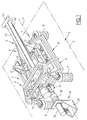
- Figure 1 illustrates a current collection assembly 1 surmounting the roof or roof 2 of a tilting rail vehicle 3. Only part of the roof 2 is shown schematically in phantom in Figure 1.
- the fixed frame 8 comprises a frame 11 of substantially square shape or rectangular, and four electrical insulators 12 each arranged at the level of a corner of the frame 11, under the latter.
- the fixed frame 8 is mounted on the roof 2 by means of the electrical insulators 12 which form support feet of the chassis 8 on the roof 2.
- the insulators 12 keep the frame 11 fixed 8 spaced apart roof 2.
- the movable chassis 9 is a frame of dimensions smaller than those of the frame 11.
- the movable frame 9 is arranged inside the fixed frame 8 and connected to this by two rigid pendulum supports 14 arranged on either side mobile chassis 9.
- Each support 14 includes a U-shaped part 15 or stirrup, the two of which branches 16 are articulated at points 17 on the front side 18 and on the rear side 19 of the frame 11, and two legs or yokes 20, extending the base 21 of the stirrup 15 down orthogonally to the branches 16, and articulated at points 22 to a lateral side of the movable chassis 9.
- the pendulum supports 14 therefore have, with respect to the direction longitudinal L of vehicle 3, a bent transverse profile, of directed concavity towards the inside of the pantograph support 7.
- Points 17 and 22 are points of articulation around parallel axes to the longitudinal direction L.
- the articulation points 17 of the branches 16 and respectively the points articulation 22 of the legs 20 of the same pendulum support 14 are aligned and spaced longitudinally, i.e. along the direction longitudinal L of the vehicle 3.
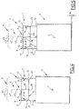
- Figure 4 schematically illustrates the vehicle body 3 in position of rest, that is to say in the absence of tilting and therefore with its roof 2 parallel to the axis of the axles of its bogies and to the plane of a railway track on which vehicle 3 is located.
- the plan of the railway is assumed to be horizontal and only the body of the vehicle 3 and the assembly 1 of current collection are shown.
- the articulation points 17 and 22 of pendulum supports 14 to the fixed 8 and mobile 9 chassis then form transversely an isosceles trapezium converging downwards, that is to say towards the roof 2 of the rail vehicle 3.
- the distance laterally separating the articulation points 17 from the two pendulum supports 14 is approximately 870 mm.
- the distance between laterally the articulation points 22 of the two pendulum supports 14 is about 760 mm.
- the distance between the points transversely of articulation 17 and 22 of the same pendulum support 14 is approximately 280 mm.
- the articulation points 17 of the pendulum supports 14 to the fixed frame 8 are located 540 mm above the roof 2.
- the movable frame 9 can pendulum laterally with respect to the fixed frame 8 on either side of its rest position shown in Figure 4, the quadrilateral formed transversely by the articulation points 17 and 22 then deforming.
- the movable frame 9 Due to the rigidity of the supports 14 and the longitudinal spacing of the points of articulation 17 and 22, the movable frame 9 is guided so satisfactory in its pendulum movement with movements limited rotation and translation interference.
- the means 10 for movement of the movable chassis 9 are arranged at the front (on the left in FIGS. 1 and 2) of the pantograph support 7 and include an electric motor 26, a reduction gear 27 and a drive arm 28.
- the electric motor 26 is fixed by a support 29 on the roof 2 of the railway vehicle 3. Its output shaft, not shown, is parallel to the longitudinal direction L and oriented rearwards. This output shaft is connected to the reducer 27 by means of an electrical insulator 30.
- the reducer 27 is flanged on the front side 18 of the frame 11 of the chassis fixed 8. Its output shaft 31 (FIG. 3) is parallel to the longitudinal direction L and extends from the front side 18 of the fixed frame 8 slightly towards the rear.
- the upper end 33 of the drive arm 28 is fixed on this output shaft 31 so that the arm 28 can pivot under the action of the motor 26 laterally around an axis X-X parallel to the longitudinal direction L.
- the lower end 34 of the arm 28 is provided with an oblong groove 35 extending lengthwise of the arm 28, at the rear of the latter.
- This slightly oblong groove 35 receives a ball joint 36 fixed on a stud 37 which projecting forward from the front side 39 of the movable chassis 9.
- the ball joint 36 and the oblong groove 35 form between the drive arm 28 and the movable frame 9 a swiveling and sliding connection radially with respect to the axis X-X.
- the ball 36 corresponding to the point of articulation of the arm 28 to the movable chassis 9, is located in the middle of the small base of the trapezoid formed by the points of articulation 17 and 22.
- the articulation point 36 is located laterally at equal distance from the points hinge 22 of the pendulum supports 14 to the movable frame 9.
- the axis X-X around which the arm 28 can pivot is located laterally equidistant from the articulation points 17 of the pendulum 14 to the fixed frame 8.
- This axis X-X is located slightly below of the level of these articulation points 17.
- the axis X-X has been shown for the sake of clarity on the large base of the trapezoid formed transversely by the points of articulation 17 and 22.
- the lower end of the arm 5 of the pantograph 4 is connected to the chassis mobile 9 so as to join laterally the arm 5 and the mobile chassis 9.
- the pendulum supports 14 are then arranged laterally on either side of the pantograph 4.
- the arm 5 is deformable between a position unfolded current collection and a folded position of reduced size, for allow the vertical translation of the bow 6 above the roof 2.
- the motor 26 is then controlled by a control unit not shown to rotate the arm 28 laterally in the opposite direction, that is to say to the right in FIG. 5.
- the movable chassis 9 is then moved laterally relative to the fixed frame 8 under the action of the drive arm 28 so that the arm 5 of the pantograph 4 is kept substantially vertical or orthogonal to the railway.
- the bow 6 is kept substantially horizontal or parallel to the plan of the railway track and the contact wire 44 of the catenary is kept in contact with the central region 43 of the bow 6.
- the arm 28 for driving the movable chassis 9 makes it possible to move this satisfactorily to ensure the counter-pendulum of the pantograph 4.
- the fixed chassis 8 and mobile 9 and the connections between these will be adapted so that the articulation point 36 describes substantially an arc of a circle, when the movable frame 9 pendulum relative to to the fixed frame 8 to provide a counter-pendulum of pendulum angles less than 10 °.
- the structure of the means 10 for moving the mobile chassis 9, in particular the lateral dimensions, of the current collection assembly 1 is relatively small. Furthermore, this assembly 1 makes it possible to ensure satisfactory the counter-pendulum of the pantograph 4. In addition, the connection between the drive means 10 and the movable frame 9 is relatively simple and therefore reliable.
- this principle can be used more generally for an assembly comprising a first chassis and a second chassis pendulum with respect to the first chassis.
- this principle can thus be applied to a bogie of a pendulum rail vehicle 3.
- the first chassis 8 comprises then at least one crosspiece supported by primary suspensions 53 on an axle 54 of the bogie, and the second chassis 9 comprises at least one cross member supporting the vehicle body 3 by means of suspensions secondary 55.
- the second chassis 9 carries the body of the vehicle rail 3 to swing it.
- the rotary arm 28 also here makes it possible to limit the lateral space requirement means 10 for lateral displacement of the second chassis 9.
- the fact that the electrical insulators 12 are part of the fixed frame 8 allows to reduce the bulk even more total vertical of the current collection assembly 1 with respect to the case where these insulators are arranged between the pantograph 4 and the movable frame 9.
- the position of the insulators 12 therefore contributes, separately, to reduce the overall size of the current collection assembly 1.
- the movable chassis 9 is maintained at a sufficient distance from the roof 2 to guarantee good electrical insulation between the chassis 9 and roof 2.
- transverse profile of the supports of pendulum 14 with concavity directed towards the inside of the pantograph support 7 allows a large angular movement of the pantograph supports 14 in a reduced volume. This characteristic makes it possible to limit even more the size of the assembly 1 of the current collection.
- the rigid pendulum supports 14 allow a satisfactory lateral guidance of the movable chassis 9 with limited friction.
- the pendulum supports 14 therefore make it possible to overcome the two jacks side and guides needed so far to train so the mobile chassis 9 is satisfactory.
- the rigid tilting supports 14 therefore also contribute, but separately, on the one hand, to the limitation of the size of the current collection assembly 1, and on the other hand, to obtain a effective counter-pendulum of the pantograph.
- the structure of the support 7 of the pantograph 4 allows the use a pantograph 4 of conventional structure.
- the arm 28 can be easily fitted, according to a variant not shown, an indexing finger of the movable frame 9 in the rest position.
- a such finger ensures precise maintenance of the movable chassis 9 in the position of rest, without energy supply, to allow the train to run in the event of failure of the displacement means 10.
- This variant can be applied from generally to an assembly comprising a first chassis and a second chassis pendulum with respect to the first chassis, for example at the assembly described with reference to FIG. 6.
Landscapes
- Engineering & Computer Science (AREA)
- Power Engineering (AREA)
- Transportation (AREA)
- Mechanical Engineering (AREA)
- Current-Collector Devices For Electrically Propelled Vehicles (AREA)
- Automatic Cycles, And Cycles In General (AREA)
- Fittings On The Vehicle Exterior For Carrying Loads, And Devices For Holding Or Mounting Articles (AREA)
- Aiming, Guidance, Guns With A Light Source, Armor, Camouflage, And Targets (AREA)
- Mechanical Pencils And Projecting And Retracting Systems Therefor, And Multi-System Writing Instruments (AREA)
- Body Structure For Vehicles (AREA)
Abstract
Description
- le bras d'entraínement est relié au deuxième châssis en un point qui décrit sensiblement un arc de cercle centré sur ledit axe longitudinal lorsque le deuxième châssis pendule par rapport au premier châssis au voisinage de sa position de repos ;
- le deuxième châssis est relié au premier châssis par au moins deux liaisons oscillantes espacées latéralement l'une de l'autre ;
- le bras d'entraínement latéral du deuxième châssis est relié à ce dernier en un point situé latéralement sensiblement à égale distance des deux liaisons oscillantes lorsque le deuxième châssis est en position de repos ;
- chaque liaison oscillante comprend un support rigide de pendulation articulé, d'une part, au premier châssis en deux points espacés longitudinalement l'un de l'autre, et d'autre part au deuxième châssis en deux points espacés longitudinalement l'un de l'autre ;
- chaque support de pendulation comprend un étrier articulé par ses branches au premier châssis, et deux chapes qui prolongent la base de l'étrier et qui sont articulées au deuxième châssis ;
- chaque support de pendulation a un profil transversal de concavité dirigée vers l'intérieur de l'ensemble ;
- les chapes de chaque support de pendulation sont sensiblement orthogonales aux branches de l'étrier correspondant ;
- les points d'articulation des supports de pendulation aux premier et deuxième châssis forment transversalement, lorsque le deuxième châssis est en position de repos, un trapèze convergeant dans le sens allant dudit axe longitudinal vers un point du deuxième châssis auquel le bras d'entraínement est relié ;
- le bras d'entraínement est relié au deuxième châssis par une liaison pivotante et coulissante ;
- l'ensemble est un ensemble de captage de courant pour un véhicule ferroviaire comprenant un pantographe et un support de pantographe, le support de pantographe comprenant le premier châssis, pour monter l'ensemble sur le toit d'un véhicule ferroviaire, et le deuxième châssis qui porte le pantographe ;
- le bras pivotant est relié au deuxième châssis en un point situé en dessous dudit axe longitudinal lorsque l'ensemble de captage de courant est monté sur le toit d'un véhicule ferroviaire ;
- le premier châssis comprend des moyens d'isolation électrique du pantographe par rapport au toit d'un véhicule ferroviaire sur lequel l'ensemble est destiné à être monté ;
- le premier châssis comprend des isolateurs électriques qui forment pieds d'appui du premier châssis sur le toit d'un véhicule ferroviaire ;
- le premier châssis comprend quatre isolateurs électriques formant pieds d'appui disposés avec une configuration générale de carré ou de rectangle ;
- les moyens de déplacement du deuxième châssis comprennent certains des moyens d'isolation électrique ;
- les moyens de déplacement du deuxième châssis comprennent un moteur rotatif d'actionnement du bras d'entraínement du deuxième châssis, et l'arbre de sortie du moteur rotatif est orienté longitudinalement ;
- le moteur rotatif est relié au bras d'entraínement par un isolateur électrique.
- la figure 1 est une vue schématique partielle et en perspective illustrant le toit d'un véhicule ferroviaire selon l'invention,
- la figure 2 est une vue schématique en perspective éclatée du support de pantographe et des moyens de déplacement de l'ensemble de captage de courant du véhicule de la figure 1,
- la figure 3 est une vue schématique, en coupe longitudinale et agrandie, illustrant la liaison entre les moyens de déplacement et le châssis mobile des figures 1 et 2,
- les figures 4 et 5 sont des vues transversales schématiques illustrant le véhicule ferroviaire de la figure 1 respectivement en position de repos et en position de pendulation, et
- la figure 6 est une vue transversale, schématique et partielle d'un autre ensemble selon l'invention appliqué à un bogie de véhicule ferroviaire pendulaire.
- un pantographe 4 comprenant lui-même un bras articulé 5 muni à une extrémité supérieure d'un archet 6,
- un support de pantographe 7 comprenant lui-même un premier châssis 8 fixe et un deuxième châssis 9 mobile, et
- des moyens 10 de déplacement du châssis mobile 9.
Claims (17)
- Ensemble (1) pour véhicule ferroviaire, du type comprenant un premier châssis (8) et un deuxième châssis (9) relié au premier châssis (8) pour penduler latéralement par rapport à celui-ci de part et d'autre d'une position de repos, l'ensemble (1) comprenant en outre des moyens (10) de déplacement latéral du deuxième châssis (9), caractérisé en ce que le deuxième châssis (9) est relié au premier châssis (8) par au moins deux liaisons oscillantes (14) espacées latéralement l'une de l'autre et en ce que les moyens (10) de déplacement comprennent un bras (28) d'entraínement latéral du deuxième châssis (9) qui est relié à ce dernier en un point (36) situé latéralement sensiblement à égale distance des deux liaisons oscillantes (14) lorsque le châssis (9) est en position de repos, lequel bras (28) est pivotant autour d'un axe longitudinal (X-X).
- Ensemble selon la revendication 1, caractérisé en ce que le bras (28) d'entraínement est relié au deuxième châssis (9) en un point (36) qui décrit sensiblement un arc de cercle centré sur ledit axe longitudinal (X-X) lorsque le deuxième châssis (9) pendule par rapport au premier châssis (8) au voisinage de sa position de repos.
- Ensemble selon la revendication 1 ou 2, caractérisé en ce que chaque liaison oscillante comprend un support rigide de pendulation (14) articulé, d'une part, au premier châssis (8) en deux points (17) espacés longitudinalement l'un de l'autre, et d'autre part au deuxième châssis (9) en deux points (22) espacés longitudinalement l'un de l'autre.
- Ensemble selon la revendication 3, caractérisé en ce que chaque support de pendulation (14) comprend un étrier (15) articulé par ses branches (16) au premier châssis (8), et deux chapes (20) qui prolongent la base de l'étrier (15) et qui sont articulées au deuxième châssis (9).
- Ensemble selon la revendication 3 ou 4, caractérisé en ce que chaque support de pendulation (14) a un profil transversal de concavité dirigée vers l'intérieur de l'ensemble (1).
- Ensemble selon les revendications 4 et 5 prises ensembles, caractérisé en ce que les chapes (20) de chaque support de pendulation (14) sont sensiblement orthogonales aux branches (16) de l'étrier (15) correspondant.
- Ensemble selon l'une quelconque des revendications 3 à 6, caractérisé en ce que les points (17, 22) d'articulation des supports de pendulation (14) aux premier et deuxième châssis (8, 9) forment transversalement, lorsque le deuxième châssis (9) est en position de repos, un trapèze convergeant dans le sens allant dudit axe longitudinal (X-X) vers un point (36) du deuxième châssis (9) auquel le bras d'entraínement (28) est relié.
- Ensemble selon l'une quelconque des revendications 1 à 7, caractérisé en ce que le bras d'entraínement (28) est relié (en 36) au deuxième châssis (9) par une liaison pivotante et coulissante.
- Ensemble selon l'une quelconque des revendications 1 à 8, caractérisé en ce que l'ensemble est une ensemble de captage de courant pour un véhicule ferroviaire comprenant un pantographe (4) et un support de pantographe (7), le support de pantographe (7) comprenant le premier châssis (8), pour monter l'ensemble (1) sur le toit (2) d'un véhicule ferroviaire, et le deuxième châssis (9) qui porte le pantographe (4).
- Ensemble selon la revendication 9, caractérisé en ce que le bras pivotant (28) est relié au deuxième châssis (9) en un point (36) situé en dessous dudit axe longitudinal (X-X) lorsque l'ensemble (1) de captage de courant est monté sur le toit (2) d'un véhicule ferroviaire.
- Ensemble selon la revendication 9 ou 10, caractérisé en ce que le premier châssis (8) comprend les moyens (12, 30) d'isolation électrique du pantographe (4) par rapport au toit (2) d'un véhicule ferroviaire sur lequel l'ensemble (1) est destiné à être monté.
- Ensemble selon la revendication 11, caractérisé en ce que le premier châssis (8) comprend des isolateurs électriques (12) qui forment pieds d'appui du premier châssis (8) sur le toit (2) d'un véhicule ferroviaire.
- Ensemble selon la revendication 12, caractérisé en ce que le premier châssis (8) comprend quatre isolateurs électriques (12) formant pieds d'appui disposés avec une configuration générale de carré ou de rectangle.
- Ensemble selon l'une quelconque des revendications 9 à 13, caractérisé en ce que les moyens (10) de déplacement du deuxième châssis comprennent certains (30) des moyens d'isolation électrique.
- Ensemble selon l'une quelconque des revendications 1 à 14, caractérisé en ce que les moyens (10) de déplacement du deuxième châssis (9) comprennent un moteur rotatif (26) d'actionnement du bras (28) d'entraínement du deuxième châssis (9), et en ce que l'arbre de sortie du moteur rotatif (26) est orienté longitudinalement.
- Ensemble selon les revendications 14 et 15 prises ensemble, caractérisé en ce que le moteur rotatif (26) est relié au bras d'entraínement (28) par un isolateur électrique (30).
- Véhicule ferroviaire, caractérisé en ce qu'il comprend un ensemble selon l'une quelconque des revendications 1 à 16.
Applications Claiming Priority (2)
| Application Number | Priority Date | Filing Date | Title |
|---|---|---|---|
| FR9914168 | 1999-11-10 | ||
| FR9914168A FR2800690B1 (fr) | 1999-11-10 | 1999-11-10 | Ensemble comprenant un premier chassis et un deuxieme chassis pendulant lateralement par rapport au premier chassis, et vehicule ferroviaire correspondant |
Publications (2)
| Publication Number | Publication Date |
|---|---|
| EP1099612A1 true EP1099612A1 (fr) | 2001-05-16 |
| EP1099612B1 EP1099612B1 (fr) | 2004-05-26 |
Family
ID=9551994
Family Applications (1)
| Application Number | Title | Priority Date | Filing Date |
|---|---|---|---|
| EP00402984A Expired - Lifetime EP1099612B1 (fr) | 1999-11-10 | 2000-10-26 | Ensemble comprenant un premier châssis et un deuxième châssis pendulant latéralement par rapport au premier châssis, et véhicule ferroviaire correspondant |
Country Status (12)
| Country | Link |
|---|---|
| US (1) | US6393998B1 (fr) |
| EP (1) | EP1099612B1 (fr) |
| JP (1) | JP2001190002A (fr) |
| KR (1) | KR100648586B1 (fr) |
| CN (1) | CN1210174C (fr) |
| AT (1) | ATE267732T1 (fr) |
| AU (1) | AU764730B2 (fr) |
| CA (1) | CA2325868C (fr) |
| DE (1) | DE60011014T2 (fr) |
| ES (1) | ES2220366T3 (fr) |
| FR (1) | FR2800690B1 (fr) |
| PL (1) | PL212196B1 (fr) |
Cited By (1)
| Publication number | Priority date | Publication date | Assignee | Title |
|---|---|---|---|---|
| EP2375422B1 (fr) * | 2010-04-09 | 2017-12-27 | Georg Jordan GmbH | Isolateur, notamment pour un pantographe d'un véhicule sur rails |
Families Citing this family (3)
| Publication number | Priority date | Publication date | Assignee | Title |
|---|---|---|---|---|
| CN110315984B (zh) * | 2019-07-18 | 2020-10-27 | 北京中车赛德铁道电气科技有限公司 | 高速受电弓防止飘弓的调整方法 |
| CN110979381B (zh) * | 2019-12-20 | 2020-11-10 | 中车长春轨道客车股份有限公司 | 基于纵置式电机和新式中心销座的构架装置 |
| CN116330984B (zh) * | 2023-04-23 | 2025-06-27 | 浙江大学软件学院(宁波)管理中心(宁波软件教育中心) | 轨道交通智能供电系统 |
Citations (2)
| Publication number | Priority date | Publication date | Assignee | Title |
|---|---|---|---|---|
| JPH0946807A (ja) * | 1995-08-01 | 1997-02-14 | Kayaba Ind Co Ltd | パンタグラフ姿勢制御装置 |
| DE29613541U1 (de) * | 1996-08-05 | 1997-06-05 | Siemens AG, 80333 München | Schienenfahrzeug |
Family Cites Families (10)
| Publication number | Priority date | Publication date | Assignee | Title |
|---|---|---|---|---|
| US1728819A (en) * | 1927-08-12 | 1929-09-17 | Gen Electric | Pantograph current collector |
| US1824871A (en) * | 1927-12-06 | 1931-09-29 | Westinghouse Electric & Mfg Co | Pantograph |
| US2935576A (en) * | 1955-05-14 | 1960-05-03 | Faiveley Louis | Current collecting device |
| SE8105354L (sv) * | 1981-09-09 | 1983-03-10 | Asea Ab | Anordning av stromavtagare pa ett sparbundet fordon |
| IT1238155B (it) * | 1990-01-10 | 1993-07-09 | Alessandro Marzocco | Pantografo per treni ad assetto variabile |
| US5124510A (en) * | 1990-08-16 | 1992-06-23 | Marvin Garfinkle | Tracking pantograph for railway electrification |
| JP2669713B2 (ja) * | 1990-11-07 | 1997-10-29 | 財団法人鉄道総合技術研究所 | 鉄道車両用パンタグラフ支持装置 |
| JPH066906A (ja) * | 1992-06-18 | 1994-01-14 | Kawasaki Heavy Ind Ltd | 集電装置 |
| DE19540913C1 (de) * | 1995-11-03 | 1997-02-06 | Deutsche Forsch Luft Raumfahrt | Stromabnehmer für die Energieübertragung zwischen einem Fahrdraht und einem Triebwagen |
| ATE303263T1 (de) * | 1997-07-01 | 2005-09-15 | Construcciones Y Aux De Ferroc | Elektrische energieaufnahmevorrichtung für neigezüge |
-
1999
- 1999-11-10 FR FR9914168A patent/FR2800690B1/fr not_active Expired - Lifetime
-
2000
- 2000-10-26 ES ES00402984T patent/ES2220366T3/es not_active Expired - Lifetime
- 2000-10-26 DE DE60011014T patent/DE60011014T2/de not_active Expired - Lifetime
- 2000-10-26 AT AT00402984T patent/ATE267732T1/de not_active IP Right Cessation
- 2000-10-26 EP EP00402984A patent/EP1099612B1/fr not_active Expired - Lifetime
- 2000-11-06 AU AU71446/00A patent/AU764730B2/en not_active Expired
- 2000-11-07 CA CA002325868A patent/CA2325868C/fr not_active Expired - Lifetime
- 2000-11-08 PL PL343750A patent/PL212196B1/pl unknown
- 2000-11-08 JP JP2000339945A patent/JP2001190002A/ja active Pending
- 2000-11-09 KR KR1020000066358A patent/KR100648586B1/ko not_active Expired - Lifetime
- 2000-11-09 US US09/708,651 patent/US6393998B1/en not_active Expired - Lifetime
- 2000-11-10 CN CNB001337920A patent/CN1210174C/zh not_active Expired - Lifetime
Patent Citations (2)
| Publication number | Priority date | Publication date | Assignee | Title |
|---|---|---|---|---|
| JPH0946807A (ja) * | 1995-08-01 | 1997-02-14 | Kayaba Ind Co Ltd | パンタグラフ姿勢制御装置 |
| DE29613541U1 (de) * | 1996-08-05 | 1997-06-05 | Siemens AG, 80333 München | Schienenfahrzeug |
Cited By (1)
| Publication number | Priority date | Publication date | Assignee | Title |
|---|---|---|---|---|
| EP2375422B1 (fr) * | 2010-04-09 | 2017-12-27 | Georg Jordan GmbH | Isolateur, notamment pour un pantographe d'un véhicule sur rails |
Also Published As
| Publication number | Publication date |
|---|---|
| US6393998B1 (en) | 2002-05-28 |
| EP1099612B1 (fr) | 2004-05-26 |
| DE60011014D1 (de) | 2004-07-01 |
| AU764730B2 (en) | 2003-08-28 |
| CA2325868C (fr) | 2006-05-09 |
| AU7144600A (en) | 2001-05-17 |
| DE60011014T2 (de) | 2005-07-28 |
| PL343750A1 (en) | 2001-05-21 |
| PL212196B1 (pl) | 2012-08-31 |
| ATE267732T1 (de) | 2004-06-15 |
| CN1210174C (zh) | 2005-07-13 |
| CA2325868A1 (fr) | 2001-05-10 |
| FR2800690A1 (fr) | 2001-05-11 |
| CN1295953A (zh) | 2001-05-23 |
| KR100648586B1 (ko) | 2006-11-24 |
| FR2800690B1 (fr) | 2001-12-07 |
| JP2001190002A (ja) | 2001-07-10 |
| ES2220366T3 (es) | 2004-12-16 |
| KR20010051556A (ko) | 2001-06-25 |
Similar Documents
| Publication | Publication Date | Title |
|---|---|---|
| EP1400398B1 (fr) | Dispositif et systéme pour le filtrage des mouvements vibratoires d'un support de passager, et support de passager equipe d'un tel systéme | |
| EP2455269B1 (fr) | Bogie de véhicule ferroviaire comprenant un dispositif de freinage à courants de Foucault | |
| CA2325867C (fr) | Ensemble de captage de courant et vehicule ferroviaire correspondant | |
| EP0945551B1 (fr) | Dispositif de balayage pour vehicule de voirie | |
| EP1099612B1 (fr) | Ensemble comprenant un premier châssis et un deuxième châssis pendulant latéralement par rapport au premier châssis, et véhicule ferroviaire correspondant | |
| EP0060189A1 (fr) | Tête de captage pour pantographe | |
| FR2698825A1 (fr) | Dispositif de liaison entre les roues et le châssis d'un véhicule. | |
| FR3061457A1 (fr) | Armature de dossier de siege comprenant une partie inferieure et une partie superieure montee mobile sur cette partie inferieure. | |
| EP2132066B1 (fr) | Bras porte-balai a cinematique pantographe pour vitre de vehicule automobile | |
| FR2577013A3 (fr) | Phare pour vehicules automobiles, comprenant un dispositif de reglage | |
| FR2826321A1 (fr) | Siege de vehicule et vehicule equipe d'un tel siege | |
| EP1497149A1 (fr) | Toit escamotable dans le coffre arriere d un vehicule | |
| FR2875196A1 (fr) | Essuie-glasse de type pantographique | |
| FR3074767A1 (fr) | Siege a support lombaire et vehicule comportant un tel siege | |
| EP3418124B1 (fr) | Siege rabattable avec dispositif de rangement pour appui-tete | |
| FR3067992B1 (fr) | Repose-pieds interieur motorise pour vehicule automobile. | |
| EP1807290B1 (fr) | Essuie-glace a pantographe | |
| FR2845369A1 (fr) | Dispositif pour transporter des personnes ou des charges dans un escalier presentant des pentes differentes et/ou des virages | |
| FR3164953A1 (fr) | Siège de véhicule | |
| FR2798051A1 (fr) | Sommier a lattes comportant un appui dorsal et un appui-tete | |
| FR2807719A1 (fr) | Siege articule | |
| FR2734781A1 (fr) | Dispositif de suspension et de basculement d'une cabine | |
| FR2720801A1 (fr) | Suspension de véhicule automobile munie d'une articulation élastique. | |
| EP0557246A1 (fr) | Dispositif de bourrage | |
| FR2887501A1 (fr) | Siege pour vehicule automobile |
Legal Events
| Date | Code | Title | Description |
|---|---|---|---|
| PUAI | Public reference made under article 153(3) epc to a published international application that has entered the european phase |
Free format text: ORIGINAL CODE: 0009012 |
|
| AK | Designated contracting states |
Kind code of ref document: A1 Designated state(s): AT BE CH CY DE DK ES FI FR GB GR IE IT LI LU MC NL PT SE |
|
| AX | Request for extension of the european patent |
Free format text: AL;LT;LV;MK;RO;SI |
|
| 17P | Request for examination filed |
Effective date: 20011116 |
|
| AKX | Designation fees paid |
Free format text: AT BE CH CY DE DK ES FI FR GB GR IE IT LI LU MC NL PT SE |
|
| GRAP | Despatch of communication of intention to grant a patent |
Free format text: ORIGINAL CODE: EPIDOSNIGR1 |
|
| GRAS | Grant fee paid |
Free format text: ORIGINAL CODE: EPIDOSNIGR3 |
|
| GRAA | (expected) grant |
Free format text: ORIGINAL CODE: 0009210 |
|
| AK | Designated contracting states |
Kind code of ref document: B1 Designated state(s): AT BE CH CY DE DK ES FI FR GB GR IE IT LI LU MC NL PT SE |
|
| PG25 | Lapsed in a contracting state [announced via postgrant information from national office to epo] |
Ref country code: AT Free format text: LAPSE BECAUSE OF FAILURE TO SUBMIT A TRANSLATION OF THE DESCRIPTION OR TO PAY THE FEE WITHIN THE PRESCRIBED TIME-LIMIT Effective date: 20040526 Ref country code: IE Free format text: LAPSE BECAUSE OF FAILURE TO SUBMIT A TRANSLATION OF THE DESCRIPTION OR TO PAY THE FEE WITHIN THE PRESCRIBED TIME-LIMIT Effective date: 20040526 Ref country code: NL Free format text: LAPSE BECAUSE OF FAILURE TO SUBMIT A TRANSLATION OF THE DESCRIPTION OR TO PAY THE FEE WITHIN THE PRESCRIBED TIME-LIMIT Effective date: 20040526 Ref country code: CY Free format text: LAPSE BECAUSE OF FAILURE TO SUBMIT A TRANSLATION OF THE DESCRIPTION OR TO PAY THE FEE WITHIN THE PRESCRIBED TIME-LIMIT Effective date: 20040526 Ref country code: FI Free format text: LAPSE BECAUSE OF FAILURE TO SUBMIT A TRANSLATION OF THE DESCRIPTION OR TO PAY THE FEE WITHIN THE PRESCRIBED TIME-LIMIT Effective date: 20040526 |
|
| REG | Reference to a national code |
Ref country code: GB Ref legal event code: FG4D Free format text: NOT ENGLISH |
|
| REG | Reference to a national code |
Ref country code: CH Ref legal event code: EP |
|
| REG | Reference to a national code |
Ref country code: IE Ref legal event code: FG4D Free format text: FRENCH |
|
| REF | Corresponds to: |
Ref document number: 60011014 Country of ref document: DE Date of ref document: 20040701 Kind code of ref document: P |
|
| REG | Reference to a national code |
Ref country code: CH Ref legal event code: NV Representative=s name: CABINET ROLAND NITHARDT CONSEILS EN PROPRIETE INDU |
|
| GBT | Gb: translation of ep patent filed (gb section 77(6)(a)/1977) |
Effective date: 20040804 |
|
| PG25 | Lapsed in a contracting state [announced via postgrant information from national office to epo] |
Ref country code: GR Free format text: LAPSE BECAUSE OF FAILURE TO SUBMIT A TRANSLATION OF THE DESCRIPTION OR TO PAY THE FEE WITHIN THE PRESCRIBED TIME-LIMIT Effective date: 20040826 Ref country code: SE Free format text: LAPSE BECAUSE OF FAILURE TO SUBMIT A TRANSLATION OF THE DESCRIPTION OR TO PAY THE FEE WITHIN THE PRESCRIBED TIME-LIMIT Effective date: 20040826 Ref country code: DK Free format text: LAPSE BECAUSE OF FAILURE TO SUBMIT A TRANSLATION OF THE DESCRIPTION OR TO PAY THE FEE WITHIN THE PRESCRIBED TIME-LIMIT Effective date: 20040826 |
|
| PG25 | Lapsed in a contracting state [announced via postgrant information from national office to epo] |
Ref country code: LU Free format text: LAPSE BECAUSE OF NON-PAYMENT OF DUE FEES Effective date: 20041026 |
|
| PG25 | Lapsed in a contracting state [announced via postgrant information from national office to epo] |
Ref country code: BE Free format text: LAPSE BECAUSE OF NON-PAYMENT OF DUE FEES Effective date: 20041031 Ref country code: MC Free format text: LAPSE BECAUSE OF NON-PAYMENT OF DUE FEES Effective date: 20041031 |
|
| NLV1 | Nl: lapsed or annulled due to failure to fulfill the requirements of art. 29p and 29m of the patents act | ||
| REG | Reference to a national code |
Ref country code: ES Ref legal event code: FG2A Ref document number: 2220366 Country of ref document: ES Kind code of ref document: T3 |
|
| REG | Reference to a national code |
Ref country code: IE Ref legal event code: FD4D |
|
| PLBE | No opposition filed within time limit |
Free format text: ORIGINAL CODE: 0009261 |
|
| STAA | Information on the status of an ep patent application or granted ep patent |
Free format text: STATUS: NO OPPOSITION FILED WITHIN TIME LIMIT |
|
| BERE | Be: lapsed |
Owner name: ALSTOM Effective date: 20041031 |
|
| 26N | No opposition filed |
Effective date: 20050301 |
|
| PG25 | Lapsed in a contracting state [announced via postgrant information from national office to epo] |
Ref country code: FR Free format text: LAPSE BECAUSE OF NON-PAYMENT OF DUE FEES Effective date: 20050630 |
|
| REG | Reference to a national code |
Ref country code: FR Ref legal event code: ST |
|
| BERE | Be: lapsed |
Owner name: *ALSTOM Effective date: 20041031 |
|
| PG25 | Lapsed in a contracting state [announced via postgrant information from national office to epo] |
Ref country code: PT Free format text: LAPSE BECAUSE OF NON-PAYMENT OF DUE FEES Effective date: 20041026 |
|
| REG | Reference to a national code |
Ref country code: CH Ref legal event code: PUE Owner name: ALSTOM TRANSPORT SA, FR Free format text: FORMER OWNER: ALSTOM, FR |
|
| REG | Reference to a national code |
Ref country code: CH Ref legal event code: PUE Owner name: ALSTOM TRANSPORT TECHNOLOGIES, FR Free format text: FORMER OWNER: ALSTOM TRANSPORT SA, FR |
|
| REG | Reference to a national code |
Ref country code: ES Ref legal event code: PC2A Owner name: ALSTOM TRANSPORT SA Effective date: 20140211 |
|
| REG | Reference to a national code |
Ref country code: GB Ref legal event code: 732E Free format text: REGISTERED BETWEEN 20140123 AND 20140129 |
|
| REG | Reference to a national code |
Ref country code: DE Ref legal event code: R082 Ref document number: 60011014 Country of ref document: DE Representative=s name: LAVOIX MUNICH, DE |
|
| REG | Reference to a national code |
Ref country code: DE Ref legal event code: R082 Ref document number: 60011014 Country of ref document: DE Representative=s name: LAVOIX MUNICH, DE Effective date: 20140416 Ref country code: DE Ref legal event code: R081 Ref document number: 60011014 Country of ref document: DE Owner name: ALSTOM TRANSPORT TECHNOLOGIES, FR Free format text: FORMER OWNER: ALSTOM, PARIS, FR Effective date: 20140416 |
|
| REG | Reference to a national code |
Ref country code: CH Ref legal event code: NV Representative=s name: CABINET ROLAND NITHARDT CONSEILS EN PROPRIETE , CH |
|
| REG | Reference to a national code |
Ref country code: DE Ref legal event code: R082 Ref document number: 60011014 Country of ref document: DE Representative=s name: LAVOIX MUNICH, DE Ref country code: DE Ref legal event code: R081 Ref document number: 60011014 Country of ref document: DE Owner name: ALSTOM TRANSPORT TECHNOLOGIES, FR Free format text: FORMER OWNER: ALSTOM TRANSPORT TECHNOLOGIES, LEVALLOIS-PERRET, FR |
|
| REG | Reference to a national code |
Ref country code: CH Ref legal event code: PCOW Free format text: NEW ADDRESS: 48 ALBERT DHALENNE, 93400 SAINT-OUEN (FR) |
|
| PGFP | Annual fee paid to national office [announced via postgrant information from national office to epo] |
Ref country code: DE Payment date: 20191021 Year of fee payment: 20 |
|
| PGFP | Annual fee paid to national office [announced via postgrant information from national office to epo] |
Ref country code: ES Payment date: 20191122 Year of fee payment: 20 Ref country code: IT Payment date: 20191028 Year of fee payment: 20 |
|
| PGFP | Annual fee paid to national office [announced via postgrant information from national office to epo] |
Ref country code: CH Payment date: 20191021 Year of fee payment: 20 |
|
| PGFP | Annual fee paid to national office [announced via postgrant information from national office to epo] |
Ref country code: GB Payment date: 20191021 Year of fee payment: 20 |
|
| REG | Reference to a national code |
Ref country code: DE Ref legal event code: R071 Ref document number: 60011014 Country of ref document: DE |
|
| REG | Reference to a national code |
Ref country code: CH Ref legal event code: PL |
|
| REG | Reference to a national code |
Ref country code: GB Ref legal event code: PE20 Expiry date: 20201025 |
|
| PG25 | Lapsed in a contracting state [announced via postgrant information from national office to epo] |
Ref country code: GB Free format text: LAPSE BECAUSE OF EXPIRATION OF PROTECTION Effective date: 20201025 |
|
| REG | Reference to a national code |
Ref country code: ES Ref legal event code: FD2A Effective date: 20220126 |
|
| PG25 | Lapsed in a contracting state [announced via postgrant information from national office to epo] |
Ref country code: ES Free format text: LAPSE BECAUSE OF EXPIRATION OF PROTECTION Effective date: 20201027 |