EP1099552B1 - Pneumatic sheet guiding device in a printing press - Google Patents
Pneumatic sheet guiding device in a printing press Download PDFInfo
- Publication number
- EP1099552B1 EP1099552B1 EP00123795A EP00123795A EP1099552B1 EP 1099552 B1 EP1099552 B1 EP 1099552B1 EP 00123795 A EP00123795 A EP 00123795A EP 00123795 A EP00123795 A EP 00123795A EP 1099552 B1 EP1099552 B1 EP 1099552B1
- Authority
- EP
- European Patent Office
- Prior art keywords
- openings
- inner part
- sheet
- format
- air
- Prior art date
- Legal status (The legal status is an assumption and is not a legal conclusion. Google has not performed a legal analysis and makes no representation as to the accuracy of the status listed.)
- Expired - Lifetime
Links
- 238000007639 printing Methods 0.000 title abstract description 31
- 238000007664 blowing Methods 0.000 abstract description 12
- 239000000758 substrate Substances 0.000 description 3
- 239000011248 coating agent Substances 0.000 description 2
- 238000000576 coating method Methods 0.000 description 2
- 239000000463 material Substances 0.000 description 2
- 206010038743 Restlessness Diseases 0.000 description 1
- 230000001419 dependent effect Effects 0.000 description 1
- 230000000694 effects Effects 0.000 description 1
- 239000000976 ink Substances 0.000 description 1
- 230000014759 maintenance of location Effects 0.000 description 1
- 238000000034 method Methods 0.000 description 1
- 238000007645 offset printing Methods 0.000 description 1
- 230000000149 penetrating effect Effects 0.000 description 1
- 239000011343 solid material Substances 0.000 description 1
Images

Classifications
-
- B—PERFORMING OPERATIONS; TRANSPORTING
- B41—PRINTING; LINING MACHINES; TYPEWRITERS; STAMPS
- B41F—PRINTING MACHINES OR PRESSES
- B41F21/00—Devices for conveying sheets through printing apparatus or machines
- B41F21/10—Combinations of transfer drums and grippers
- B41F21/106—Combinations of transfer drums and grippers for reversing sheets, e.g. for perfecting machine
- B41F21/108—Combinations of transfer drums and grippers for reversing sheets, e.g. for perfecting machine with pneumatic means
-
- B—PERFORMING OPERATIONS; TRANSPORTING
- B41—PRINTING; LINING MACHINES; TYPEWRITERS; STAMPS
- B41F—PRINTING MACHINES OR PRESSES
- B41F21/00—Devices for conveying sheets through printing apparatus or machines
- B41F21/10—Combinations of transfer drums and grippers
- B41F21/102—Combinations of transfer drums and grippers with pneumatic means
Definitions
- the invention relates to a pneumatic sheet guiding device in a printing press according to the preamble of Main claim.
- EP 0 802 053 A1 A sheet guiding device of this type is out EP 0 802 053 A1 is known.
- On a hollow blowpipe are over the format width of several of the curvature of a printing press cylinder adapted guide elements arranged, the outlet openings for pressing the sheet onto the outer surface of the Have cylinders with air.
- everyone is on the blowpipe Guide element an actuator for switching on and off Blown air assigned.
- Each actuator instructs Closure element, which one between each guide element and assigned to the blow pipe arranged throughflow opening is.
- Another sheet guiding device is known from DE 36 08 795 A1 known. Then the arrangement is before and after a pressure zone a blowpipe acting across the width of the arc known with nozzles, an actuator between the arc and blowpipe exhibit.
- DE 195 30 039 C2 describes a blowing device in a printing press to support the sheet guidance on a cylindrical Body while avoiding blowing the side edges and known considering the basis weight.
- an inner blowpipe - when processing Cardboard - or the inner and one outer blowpipe - at Processing of paper - to support the sheet guidance used.
- the outer blow pipe has nozzle holes Influencing the arch in the edge area.
- the inner tube is fixed to the outer tube and faces the outer tube penetrating holes to influence the arc in the Midrange. Blowing air is optionally available through switching valves the inner blowpipe or the inner one and the outer blowpipe can be realized.
- the disadvantage here is that the blowing device is relative is complex and too little the different format widths sheet-shaped substrates in a printing machine.
- the sheet guiding device can only be operated in blown air mode.
- a device that is used exclusively in suction air mode is controllable is known from DE 198 16 313 A1 and is in a turning drum for suction air control of the suction system used.
- the device has rotary vane by default for suction air control for individual adjustment sections on.
- Several suction chambers are juxtaposed in sections controllable with suction air, whereby within the Section of each suction chamber by means of an oscillating shaft stored control shaft can be acted upon with suction air.
- the rotatable control shaft each section assigned (with suction chambers) and distributed over the circumference - several axial, circumferentially connected control channels of different Length on to bores of the suction chambers with suction air head for.
- a plate exposure device in which the recording medium, especially the pressure plate, using vacuum slots on a support surface a drum can be fixed.
- a drain manifold arranged for the targeted intake of air.
- the drain manifold has parallel arranged, provided with holes cylinder channels, wherein the holes are connected to the vacuum slots via conduit channels.
- the cylinder channels are preferably by means of a master cylinder, the one provided with openings Has rotary piston, can be targeted with a negative pressure.
- a sheet guiding device which can be operated in two operating modes.
- a plurality of rollers arranged at intervals and adjustable to pressure-free areas are used as sheet guiding elements on a tube which extends across the width of the printing press.
- the sheet is guided pneumatically.
- a second tube which is stored in the tube, is acted upon by blown air, which flows out from nozzles distributed over the tube in the direction of the sheet material.
- the second tube is coupled by means of a drive mechanism, so that the second tube can be moved vertically and the nozzles of the second tube can pass through openings in the first tube.
- This mode of operation can be used for sheet material that has no pressure-free areas.
- the invention has for its object a pneumatic Sheet guiding device of the type described in the introduction create that avoids the disadvantages mentioned is adjustable to the sheet format to be processed and can be operated with blown air or suction air.
- a first advantage is due to the fact that the invention Sheet guiding device has a simple structure and can be produced with little effort.
- this pneumatic sheet guide device universal within a printing press, especially a rotary printing press, along the sheet transport path can be used.
- a pneumatic sheet guide device as well an adjacent multiple arrangement of this pneumatic Sheet guiding devices can be implemented and depending on requirements is the sheet guiding device with variable format Blowing air or suction air can be applied.
- the sheet guiding device according to the invention before and / or after a printing nip as a pressure cylinder blowing device used. It is also in the sheet outlet of a sheet guide cylinder, e.g. below the transfer area of two Bow holding systems, can be used.
- a printing nip a printing unit or a coating unit
- a sheet guide cylinder e.g. below the transfer area of two Bow holding systems.
- the sheet guiding device according to the invention is independent from an assignment to a sheet guide cylinder also in Boom can be used to support sheet transport.
- a blown air mode is available for the lubrication-free sheet transport or suction air operation, e.g. for hovering or for frictionally guiding the bends, realizable.
- the pneumatic sheet guiding device it is advantageous that it can be designed as a sheet holding system to which suction air can be applied in a sheet guiding cylinder.
- the sheet guiding device according to the invention can preferably be used here as a tubular suction system with suction devices arranged at intervals in the axial direction in a turning device, for example a turning drum.
- a major advantage is that the connection or disconnection of blowing or suction air in the sheet guiding device according to the invention format variable is feasible. This points the pneumatically actuated sheet guiding device at least a number of across the maximum format width a printing machine reaching openings in the Range between minimum format and maximum format can be switched on or can be switched off for the passage of air.
- the sheet guiding device for symmetrical and asymmetrical sheet processing can be used in a printing press.
- the sheet guiding device is also sheet processing Can be used in a variety of formats.
- printing units in a sheet-fed rotary printing press preferably offset printing units, with sheet-guiding printing cylinders, Blanket cylinders, plate cylinders and at least Inks arranged in a row.
- the sheet transport is by means of Transfer cylinders between the printing units can be realized.
- the Turning device is for example as a single drum application formed and has in addition to at least one gripper system a suction system as sheet retention systems. It is Suction system through the sheet guide device according to the invention educated.
- Another training is in a printing unit / coating unit before and / or after a pressure zone, e.g. from blanket cylinder and pressure cylinder formed, a blowing device arranged, which means guiding a sheet on the impression cylinder Blown air jets supported.
- a blowing device formed by the sheet guide device according to the invention.
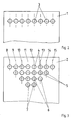
- the pneumatic sheet guide device has according to the invention The following structure: It is a tubular outer part 1 provided that at least over the maximum format width a printing press is sufficient and at least in the axial direction has a series of openings 3 for the passage of air.
- the openings 3 extend over the maximum format the printing press.
- the openings 3 are, for example, in training at a defined angle, especially in Outside area, arranged obliquely to the arch in the blown air mode in the direction of conveyance or in the direction of the side edge.
- the openings 3 are e.g. when training the invention Sheet guiding device as a pressure cylinder blowing device directed to the outer surface of the printing cylinder to blow air on the pressure cylinder in the gripper closure directed bow.
- the sheet guiding device When the sheet guiding device is designed as a suction system a turning drum with an outer part 1 as a suction tube are on the pivotally mounted outer part 1, under Taking into account the gripper pitch at intervals in the axial direction, Suction fingers for sucking the trailing edge of the sheet arranged. In this training, the suction fingers wear Openings 3 for the passage of air, which with the interior of the outer part 1 (suction pipe) on the line side in functional connection are.
- a tubular inner part 2 is concentrically assigned to the tubular outer part 1 so that it can rotate and is preferably axially movable.
- the tubular inner part 2 has at least one row of control openings 4 in the axial direction for controlling the passage of air, which extend at several intervals 8 to 15 across the maximum format width of a printing press in the axial direction.
- the maximum format is thus defined by the distances 8 to 15.
- the tubular inner part 2 has further rows of control openings 5, 6, 7 for the variable-format control of the air passage in the axial direction, which are arranged circumferentially on the inner part 2 analogously to the control openings 4.
- control openings 4 or 5 or 6 or 7 Inner part 2, the distances 8 - 15 are in the same division the distances between the openings 3 (outer part 1). there the control openings 7 extend at intervals 11, 12 about the minimum format width of a printing press.
- the Minimal format is thus through the control openings 7 with the Distances 11, 12 defined.
- the between the minimal format and the further format arranged further rows of control openings 5 with the distances 9 to 14 or control openings 6 with the distances 10 to 13 preferably correspond to Format widths which can usually be processed in printing presses.
- the rows of control openings 4-7 are preferably at intervals 8 - 15 for the maximum format at intervals of 11.12 for the minimal format has multiple levels, especially for intermediate formats, arranged.
- the outer part 1 and the concentrically inserted inner part 2 are tightly arranged on the end face.
- At least the inner part 2 is connected to an air generator by means of at least one axially and / or radially feeding supply line in order to optionally supply the sheet guiding device with suction air or blown air.
- At least the inner part 2 is rotatable, preferably additionally axially movable, to the outer part 1.
- the inner part 2 can be rotated about the axis manually or by means of an actuating device in defined positions corresponding to the rows of control openings 4-7.
- the inner part 2 is also preferably axially movable to the outer part 1. This is advantageous, for example, for asymmetrical sheet processing in the printing press.
- the inner part 2 is axially movable relative to the outer part 1.
- the control openings 4 or 5 or 6 or 7 can be moved axially offset by at least a distance of the distances 8-15 and can be fixed in the end position, which corresponds to the difference between the originally symmetrical and asymmetrical sheet processing.
- the prerequisite here is that the distances 8-15 from control openings 4-7 to openings 3 are the same.
- the positioning of the inner part 2 can preferably be achieved by means of a ball catch using an actuating device.
- the pneumatic sheet guiding device is depending on the requirement in the operating modes "blown air mode” or “suction air mode” clocked operable.
- the outer part 1 can be fixed to the frame or rotated, e.g. by means of an actuator his.
- the rotatable mounting of the outer part 1 is for example advantageous if the sheet guiding device as a pressure cylinder blowing device at different angles of inclination Blast air jets aimed at the bow.
- Each actuating device with a central is preferred Control, e.g. a control center, a printing press in terms of circuitry connected so that at least twisting the Inner part 2, if necessary also turning the outer part 1, can be carried out automatically.
- Control e.g. a control center
- a printing press in terms of circuitry connected so that at least twisting the Inner part 2, if necessary also turning the outer part 1, can be carried out automatically.
- In further training is in addition to the rotation of the inner part 2, its axial Movement can be carried out automatically.
- control openings are in minimal format 7 at a distance 11, 12 with the corresponding openings 3 of the outer part 1 in functional connection and the end Openings 3 (distances 8 to 10; 13 to 15) are closed.
- Openings 3 and control openings 4 to 7 are not based on the number specified here Openings 3 and control openings 4 to 7 limited. Much more are further rows of control openings on the circumference Inner part 2 for different format widths, preferably graduated, can be arranged.
- the openings 3 and the control openings 4 - 7, including additional openings (3 or 4-7), are preferably designed as bores or slots.
Landscapes
- Supply, Installation And Extraction Of Printed Sheets Or Plates (AREA)
- Feeding Of Articles By Means Other Than Belts Or Rollers (AREA)
- Delivering By Means Of Belts And Rollers (AREA)
- Advancing Webs (AREA)
- Separation, Sorting, Adjustment, Or Bending Of Sheets To Be Conveyed (AREA)
- Discharge By Other Means (AREA)
- Facsimile Scanning Arrangements (AREA)
Abstract
Description
Die Erfindung betrifft eine pneumatische Bogenführungseinrichtung in einer Druckmaschine nach dem Oberbegriff des Hauptanspruches.The invention relates to a pneumatic sheet guiding device in a printing press according to the preamble of Main claim.
Eine Bogenführungseinrichtung dieser Art ist aus
EP 0 802 053 A1 bekannt. An einem hohlen Blasrohr sind über
die Formatbreite mehrere der Krümmung eines Druckmaschinenzylinders
angepasste Leitelemente angeordnet, die Austrittsöffnungen
zum Anpressen des Bogens auf die Mantelfläche des
Zylinders mittels Luft aufweisen. Am Blasrohr ist jedem
Leitelement eine Stelleinrichtung zum Zu- und Abschalten der
Blasluft zugeordnet. Dabei weist jede Stelleinrichtung ein
Verschlusselement auf, welches einer zwischen jedem Leitelement
und dem Blasrohr angeordneten Durchströmöffnung zugeordnet
ist.A sheet guiding device of this type is out
Aus DE 36 08 795 A1 ist eine weitere Bogenführungseinrichtung bekannt. Danach ist vor und nach einer Druckzone die Anordnung eines über die Breite des Bogens wirkenden Blasrohres mit Düsen bekannt, die zwischen Bogen und Blasrohr ein Stellelement aufweisen.Another sheet guiding device is known from DE 36 08 795 A1 known. Then the arrangement is before and after a pressure zone a blowpipe acting across the width of the arc known with nozzles, an actuator between the arc and blowpipe exhibit.
Von Nachteil ist, dass die Bogenführungseinrichtungen relativ aufwendig sind und ausschließlich mit Blasluft betreibbar sind. Aus DE 36 08 795 A1 sind unter dem Aspekt der Berücksichtigung des Bogenformates keine Hinweise zu entnehmen. Über das Bogenformat hinausgehende Luftaustrittsöffnungen wirken sich bekanntlich negativ auf die Bogenführung aus, da an den Seitenkanten der Bogen unterblasen werden kann. Dies führt zu einem unruhigen Bogenlauf und fördert die Abschmiergefahr. The disadvantage is that the sheet guiding devices are relative are complex and can only be operated with blown air are. From DE 36 08 795 A1 are taking into account the aspect no information can be found in the sheet format. Air outlet openings that go beyond the sheet format are known to have a negative effect on the sheet guidance, since can be blown at the side edges of the sheet. This leads to a restless sheet run and promotes the risk of greasing.
Aus DE 195 30 039 C2 ist eine Blaseinrichtung in einer Druckmaschine zur Unterstützung der Bogenführung auf einem zylindrischen Körper unter Vermeidung des Unterblasens der Seitenkanten und bei Berücksichtigung des Flächengewichtes bekannt. Hierbei ist ein inneres Blasrohr - bei Verarbeitung von Karton - oder das innere und ein äußeres Blasrohr - bei Verarbeitung von Papier - zur Unterstützung der Bogenführung einsetzbar. Das äußere Blasrohr weist Düsenbohrungen zur Beeinflussung des Bogens im Randbereich auf. Das innere Rohr ist zum äußeren Rohr feststehend und weist das äußere Rohr durchdringende Bohrungen auf zur Beeinflussung des Bogens im Mittenbereich. Durch Schaltventile ist wahlweise eine Blasluftbeaufschlagung des inneren Blasrohres oder des inneren und des äußeren Blasrohres realisierbar.DE 195 30 039 C2 describes a blowing device in a printing press to support the sheet guidance on a cylindrical Body while avoiding blowing the side edges and known considering the basis weight. Here is an inner blowpipe - when processing Cardboard - or the inner and one outer blowpipe - at Processing of paper - to support the sheet guidance used. The outer blow pipe has nozzle holes Influencing the arch in the edge area. The inner tube is fixed to the outer tube and faces the outer tube penetrating holes to influence the arc in the Midrange. Blowing air is optionally available through switching valves the inner blowpipe or the inner one and the outer blowpipe can be realized.
Von Nachteil ist hierbei, dass die Blaseinrichtung relativ aufwendig ist und zu wenig die unterschiedlichen Formatbreiten bogenförmiger Bedruckstoffe in einer Druckmaschine berücksichtigt. Darüber hinaus ist die Bogenführungseinrichtung ausschließlich im Blasluftbetrieb betreibbar.The disadvantage here is that the blowing device is relative is complex and too little the different format widths sheet-shaped substrates in a printing machine. In addition, the sheet guiding device can only be operated in blown air mode.
Eine Einrichtung, welche ausschließlich im Saugluftbetrieb steuerbar ist, ist aus der DE 198 16 313 A1 bekannt und ist in einer Wendetrommel zur Saugluftsteuerung des Saugersystems eingesetzt. Die Einrichtung weist als Voreinstellung Drehschieber zur Saugluftsteuerung für einzelne Einstellabschnitte auf. Mehrere Saugkammern sind abschnittsweise nebeneinanderliegend mit Saugluft ansteuerbar, wobei innerhalb des Abschnittes jede Saugkammer mittels einer in einer Schwingwelle gelagerten Steuerwelle mit Saugluft beaufschlagbar ist. Dabei weist die verdrehbare Steuerwelle - jedem Abschnitt (mit Saugkammern) zugeordnet und am Umfang verteilt - mehrere axiale, umfangsseitig verbundene Steuerkanäle unterschiedlicher Länge auf, um Bohrungen der Saugkammern mit Saugluft anzusteuern.A device that is used exclusively in suction air mode is controllable, is known from DE 198 16 313 A1 and is in a turning drum for suction air control of the suction system used. The device has rotary vane by default for suction air control for individual adjustment sections on. Several suction chambers are juxtaposed in sections controllable with suction air, whereby within the Section of each suction chamber by means of an oscillating shaft stored control shaft can be acted upon with suction air. The rotatable control shaft - each section assigned (with suction chambers) and distributed over the circumference - several axial, circumferentially connected control channels of different Length on to bores of the suction chambers with suction air head for.
Aus EP-A-0883 279 ist eine Plattenbelichtungsvorrichtung bekannt, bei der das Aufzeichnungsmedium, speziell die Druckplatte, mittels Unterdruckschlitzen an einer Stützfläche einer Trommel fixierbar ist. Zwischen der Unterdruckquelle und den Schlitzen ist ein Ablaufverteiler zum gezielten Ansaugen von Luft angeordnet. Der Ablaufverteiler weist parallel zueinander angeordnete, mit Löchern versehene Zylinderkanäle auf, wobei die Löcher über Leitungskanäle mit den Unterdruckschlitzen verbunden sind. Die Zylinderkanäle sind vorzugsweise mittels eines Hauptzylinders, der einen mit Öffnungen versehenen Rotationskolben aufweist, gezielt mit einem Unterdruck beaufschlagbar.From EP-A-0883 279 a plate exposure device is known in which the recording medium, especially the pressure plate, using vacuum slots on a support surface a drum can be fixed. Between the vacuum source and the slots a drain manifold arranged for the targeted intake of air. The drain manifold has parallel arranged, provided with holes cylinder channels, wherein the holes are connected to the vacuum slots via conduit channels. The cylinder channels are preferably by means of a master cylinder, the one provided with openings Has rotary piston, can be targeted with a negative pressure.
Gemäß DE-A-38 35 266 ist eine Bogenführungseinrichtung bekannt, die in zwei Betriebsweisen
betreibbar ist. In der ersten Betriebsweise werden auf einem über die Breite
der Druckmaschine sich erstreckenden Rohr mehrere in Abständen angeordnete, auf
druckfreie Bereiche einstellbare Rollen als Bogenführungselemente eingesetzt.
In der zweiten Betriebsweise erfolgt die Bogenführung pneumatisch. Hierzu wird ein in
dem Rohr gelagertes, zweites Rohr mit Blasluft beaufschlagt, welche aus über das Rohr
verteilte Düsen in Richtung Bogenmaterial ausströmt. Das zweite Rohr ist mittels eines
Antriebsmechanismus gekoppelt, so dass das zweite Rohr vertikal bewegbar und die
Düsen des zweiten Rohres durch Öffnungen des ersten Rohres hindurchtreten können.
Diese Betriebsweise ist für Bogenmaterial einsetzbar, das keine druckfreien Bereiche
aufweist.According to DE-A-38 35 266, a sheet guiding device is known which can be operated in two operating modes. In the first mode of operation, a plurality of rollers arranged at intervals and adjustable to pressure-free areas are used as sheet guiding elements on a tube which extends across the width of the printing press.
In the second mode of operation, the sheet is guided pneumatically. For this purpose, a second tube, which is stored in the tube, is acted upon by blown air, which flows out from nozzles distributed over the tube in the direction of the sheet material. The second tube is coupled by means of a drive mechanism, so that the second tube can be moved vertically and the nozzles of the second tube can pass through openings in the first tube. This mode of operation can be used for sheet material that has no pressure-free areas.
Der Erfindung liegt die Aufgabe zugrunde, eine pneumatische Bogenführungseinrichtung der eingangs beschriebenen Art zu schaffen, die die genannten Nachteile vermeidet, die auf das zu verarbeitende Bogenformat einstellbar ist und mit Blasluft oder Saugluft betreibbar ist.The invention has for its object a pneumatic Sheet guiding device of the type described in the introduction create that avoids the disadvantages mentioned is adjustable to the sheet format to be processed and can be operated with blown air or suction air.
Gelöst wird dies erfindungsgemäß durch die Ausbildungsmerkmale des Hauptanspruches. Weiterbildungen ergeben sich aus den Unteransprüchen.According to the invention, this is solved by the training features of the main claim. Further training results from the Dependent claims.
Ein erster Vorteil ist darin begründet, dass die erfindungsgemäße Bogenführungseinrichtung einen einfachen Aufbau aufweist und mit geringem Aufwand herstellbar ist.A first advantage is due to the fact that the invention Sheet guiding device has a simple structure and can be produced with little effort.
Von Vorteil ist weiterhin, dass diese pneumatische Bogenführungseinrichtung universell innerhalb einer Druckmaschine, insbesondere einer Rotationsdruckmaschine, entlang des Bogentransportweges einsetzbar ist. Dabei ist die einzelne Anordnung einer pneumatischen Bogenführungseinrichtung als auch eine benachbarte Mehrfachanordnung dieser pneumatischen Bogenführungseinrichtungen realisierbar und je nach Anforderung ist die Bogenführungseinrichtung formatvariabel mit Blasluft oder Saugluft beaufschlagbar.Another advantage is that this pneumatic sheet guide device universal within a printing press, especially a rotary printing press, along the sheet transport path can be used. Here is the individual arrangement a pneumatic sheet guide device as well an adjacent multiple arrangement of this pneumatic Sheet guiding devices can be implemented and depending on requirements is the sheet guiding device with variable format Blowing air or suction air can be applied.
Beispielsweise ist die erfindungsgemäße Bogenführungseinrichtung vor und/oder nach einem Druckspalt (eines Druckwerkes oder eines Lackwerkes) als Druckzylinderblasvorrichtung einsetzbar. Sie ist ebenso im Bogenabgang eines Bogenfuhrungszylinders, z.B. unterhalb des Übergabebereiches von zwei Bogenhaltesystemen, einsetzbar. Bei im Schöndruck erstellten Bogen ist die Bogenführungseinrichtung dabei im Saugluftbetrieb und bei im Schön- und Widerdruck erstellten Bogen ist diese im Blasluftbetrieb betreibbar.For example, the sheet guiding device according to the invention before and / or after a printing nip (a printing unit or a coating unit) as a pressure cylinder blowing device used. It is also in the sheet outlet of a sheet guide cylinder, e.g. below the transfer area of two Bow holding systems, can be used. When created in straight printing Bow is the sheet guiding device in suction air mode and for sheets that are created in face and reverse printing these can be operated in blown air mode.
Die erfindungsgemäße Bogenführungseinrichtung ist unabhängig von einer Zuordnung zu einem Bogenführungszylinder auch im Ausleger zur Unterstützung des Bogentransportes einsetzbar. Je nach Anforderung ist hierbei ein Blasluftbetrieb für den abschmierfreien Bogentransport oder ein Saugluftbetrieb, z.B. zur Schwebeführung oder zum reibschlüssigen Führen der Bogen, realisierbar.The sheet guiding device according to the invention is independent from an assignment to a sheet guide cylinder also in Boom can be used to support sheet transport. Depending on the requirement, a blown air mode is available for the lubrication-free sheet transport or suction air operation, e.g. for hovering or for frictionally guiding the bends, realizable.
In einer Ausbildung der pneumatischen Bogenführungseinrichtung
ist von Vorteil, dass diese als mit Saugluft beaufschlagbares
Bogenhaltesystem in einem Bogenführungszylinder
ausführbar ist.
Bevorzugt ist hierbei die erfindungsgemäße Bogenführungseinrichtung
als rohrförmiges Saugersystem mit in Achsrichtung in
Abständen angeordneten Saugern in einer Wendeeinrichtung,
z.B. einer Wendetrommel, einsetzbar.In an embodiment of the pneumatic sheet guiding device, it is advantageous that it can be designed as a sheet holding system to which suction air can be applied in a sheet guiding cylinder.
The sheet guiding device according to the invention can preferably be used here as a tubular suction system with suction devices arranged at intervals in the axial direction in a turning device, for example a turning drum.
Ein wesentlicher Vorteil ist, dass die Zu- bzw. Abschaltung von Blas- oder Saugluft in der erfindungsgemäßen Bogenführungeinrichtung formatvariabel realisierbar ist. Hierzu weist die pneumatisch beaufschlagbare Bogenführungseinrichtung wenigstens eine Reihe von über die maximale Formatbreite einer Druckmaschine reichenden Öffnungen auf, die in dem Bereich zwischen Minimalformat und Maximalformat zuschaltbar bzw. abschaltbar für den Luftdurchtritt sind.A major advantage is that the connection or disconnection of blowing or suction air in the sheet guiding device according to the invention format variable is feasible. This points the pneumatically actuated sheet guiding device at least a number of across the maximum format width a printing machine reaching openings in the Range between minimum format and maximum format can be switched on or can be switched off for the passage of air.
Schließlich ist es vorteilhaft, dass die Bogenführungseinrichtung für eine symmetrische als auch asymmetrische Bogenverarbeitung in einer Druckmaschine einsetzbar ist. Bei asymmetrischer Bogenverarbeitung ist die Bogenführungseinrichtung auch formatvariabel einsetzbar. Finally, it is advantageous that the sheet guiding device for symmetrical and asymmetrical sheet processing can be used in a printing press. With asymmetrical The sheet guiding device is also sheet processing Can be used in a variety of formats.
Die Erfindung soll nachstehend an einem Ausführungsbeispiel näher erläutert werden. Dabei zeigen schematisch:
- Fig. 1
- eine pneumatisch beaufschlagbare Bogenführungseinrichtung in zweiteiliger Ausbildung,
- Fig. 2
- ein Lochbild des ersten Teiles gemäß
Figur 1, - Fig. 3
- ein Lochbild des zweiten Teiles gemäß
Figur 1.
- Fig. 1
- a pneumatically actuated sheet guiding device in two parts,
- Fig. 2
- 2 shows a hole pattern of the first part according to FIG. 1,
- Fig. 3
- 2 shows a hole pattern of the second part according to FIG. 1.
In einer Bogenrotationsdruckmaschine sind mehrere Druckwerke, vorzugsweise Offsetdruckwerke, mit bogenführenden Druckzylindern, Gummituchzylindern, Plattenzylindern und zumindest Farbwerken in Reihe angeordnet. Der Bogentransport ist mittels Transferzylindern zwischen den Druckwerken realisierbar.There are several printing units in a sheet-fed rotary printing press, preferably offset printing units, with sheet-guiding printing cylinders, Blanket cylinders, plate cylinders and at least Inks arranged in a row. The sheet transport is by means of Transfer cylinders between the printing units can be realized.
Bei Bogenrotationsdruckmaschinen für den Schön- sowie Schön- und Widerdruck ist zwischen wenigstens zwei Druckwerken eine Wendeeinrichtung für die Bogen angeordnet, welche bevorzugt nach dem Prinzip der Hinterkantenwendung betreibbar ist. Die Wendeeinrichtung ist beispielsweise als Eintrommelwendung ausgebildet und weist neben wenigstens einem Greifersystem ein Saugersystem als Bogenhaltesysteme auf. Dabei ist das Saugersystem durch die erfindungsgemäße Bogenführungseinrichtung ausgebildet.In sheet-fed rotary printing presses for the Schön- and Schön- and back pressure is one between at least two printing units Arranging device for the sheets arranged, which is preferred is operable according to the principle of trailing edges. The Turning device is for example as a single drum application formed and has in addition to at least one gripper system a suction system as sheet retention systems. It is Suction system through the sheet guide device according to the invention educated.
In einer weiteren Ausbildung ist in einem Druckwerk/Lackwerk vor und/oder nach einer Druckzone, z.B. aus Gummituchzylinder und Druckzylinder gebildet, eine Blasvorrichtung angeordnet, die die Führung eines Bogens auf dem Druckzylinder mittels Blasluftstrahlen unterstützt. Dabei ist die Blasvorrichtung durch die erfindungsgemäße Bogenführungseinrichtung ausgebildet.Another training is in a printing unit / coating unit before and / or after a pressure zone, e.g. from blanket cylinder and pressure cylinder formed, a blowing device arranged, which means guiding a sheet on the impression cylinder Blown air jets supported. Here is the blowing device formed by the sheet guide device according to the invention.
Die pneumatische Bogenführungseinrichtung hat erfindungsgemäß
nachstehenden Aufbau: Es ist ein rohrförmiges Außenteil 1
vorgesehen, dass zumindest über die maximale Formatbreite
einer Druckmaschine reicht und in axialer Richtung wenigstens
eine Reihe von Öffnungen 3 für den Luftdurchtritt aufweist.
Dabei erstrecken sich die Öffnungen 3 über das Maximalformat
der Druckmaschine. Die Öffnungen 3 sind beispielsweise in
einer Ausbildung in einem definierten Winkel, insbesondere im
Außenbereich, schräg angeordnet, um den Bogen im Blasluftbetrieb
in Förderrichtung bzw. in Richtung Seitenkante auszustreichen.The pneumatic sheet guide device has according to the invention
The following structure: It is a tubular
Die Öffnungen 3 sind z.B. bei Ausbildung der erfindungsgemäßen Bogenführungseinrichtung als Druckzylinderblasvorrichtung auf die Mantelfläche des Druckzylinders gerichtet, um Blasluftstrahlen auf den im Greiferschluß auf den Druckzylinder geführten Bogen zu richten.The openings 3 are e.g. when training the invention Sheet guiding device as a pressure cylinder blowing device directed to the outer surface of the printing cylinder to blow air on the pressure cylinder in the gripper closure directed bow.
Bei einer Ausbildung der Bogenführungseinrichtung als Saugersystem
einer Wendetrommel mit einem Außenteil 1 als Saugerrohr
sind an dem schwenkbar gelagerten Außenteil 1, unter
Berücksichtigung der Greiferteilung in Abständen in Achsrichtung,
Saugerfinger für das Ansaugen der Bogenhinterkante
angeordnet. In dieser Ausbildung tragen die Saugerfinger die
Öffnungen 3 für den Luftdurchtritt, welche mit dem Inneren
des Außenteiles 1 (Saugerrohr) leitungsseitig in Funktionsverbindung
sind. When the sheet guiding device is designed as a suction system
a turning drum with an
Dem rohrförmigen Außenteil 1 ist konzentrisch ein rohrförmiges
Innenteil 2 drehbar und vorzugsweise axial bewegbar
zugeordnet. Das rohrförmige Innenteil 2 weist in Achsrichtung
wenigstens eine Reihe von Steueröffnungen 4 für die Steuerung
des Luftdurchtrittes auf, welche sich in mehreren Abständen 8
bis 15 über die maximale Formatbreite einer Druckmaschine in
Achsrichtung erstrecken. Das Maximalformat ist somit durch
die Abstände 8 bis 15 definiert.
Weiterhin weist das rohrförmige Innenteil 2 in Achsrichtung
formatvariabel weitere Reihen von Steueröffnungen 5, 6, 7 für
die formatvariable Steuerung des Luftdurchtrittes auf, welche
analog der Steueröffnungen 4 umfangsseitig am Innenteil 2
angeordnet sind.A tubular
Furthermore, the tubular
In jeder Reihe der Steueröffnungen 4 oder 5 oder 6 oder 7
(Innenteil 2) sind die Abstände 8 - 15 in gleicher Teilung zu
den Abständen der Öffnungen 3 (Außenteil 1) angeordnet. Dabei
erstrecken sich die Steueröffnungen 7 in den Abständen 11, 12
über die minimale Formatbreite einer Druckmaschine. Das
Minimalformat ist somit durch die Steueröffnungen 7 mit den
Abständen 11, 12 definiert. Die zwischen dem Minimalformat
und dem Maximalformat angeordneten weiteren Reihen von Steueröffnungen
5 mit den Abständen 9 bis 14 bzw. Steueröffnungen
6 mit den Abständen 10 bis 13 entsprechen bevorzugt den
üblicherweise in Druckmaschinen verarbeitbaren Formatbreiten.
Bevorzugt sind die Reihen von Steueröffnungen 4 - 7 in Abständen
8 - 15 für das Maximalformat zu Abständen 11,12 für
das Minimalformat mehrfach gestuft, insbesondere für Zwischenformate,
angeordnet.In each row of
Das Außenteil 1 und das konzentrisch eingesetzte
Innenteil 2 sind stirnseitig dicht angeordnet. Zumindest das
Innenteil 2 ist mittels wenigstens einer axial und/oder
radial einspeisenden Versorgungsleitung mit einem Lufterzeuger
verbunden, um wahlweise die Bogenführungseinrichtung mit
Saugluft bzw. Blasluft zu versorgen. Zumindest das Innenteil
2 ist zum Außenteil 1 drehbar, bevorzugt zusätzlich axial
bewegbar, angeordnet. Das Verdrehen des Innenteils 2 um die
Achse ist manuell oder mittels einer Betätigungseinrichtung
in definierten Positionen entsprechend der Reihen von Steueröffnungen
4 - 7 realisierbar.
Das Innenteil 2 ist darüber hinaus bevorzugt axial zum Außenteil
1 bewegbar. Dies ist beispielsweise bei asymmetrischer
Bogenverarbeitung in der Druckmaschine von Vorteil. Hierbei
ist bevorzugt nachdem umfangsseitig eine Reihe des Innenteiles
2 mit den entsprechenden Steueröffnungen 4 oder 5 oder 6
oder 7 zu einer Reihe von Öffnungen 3 des Außenteiles 1
deckungsgleich positioniert ist, das Innenteil 2 zum Außenteil
1 axial bewegbar. Dabei sind die Steueröffnungen 4 oder
5 oder 6 oder 7 um wenigstens einen Abstand der Abstände 8-15
axial versetzt bewegbar und in der Endposition fixierbar, der
der Differenz von der ursprünglich symmetrischen zur asymmetrischen
Bogenverarbeitung entspricht. Voraussetzung ist
hierbei, dass die Abstände 8-15 von Steueröffnungen 4-7 zu
den Öffnungen 3 gleich sind. Das Positionieren des Innenteiles
2 ist bevorzugt mittels Kugelrast unter Verwendung einer
Betätigungseinrichtung realisierbar.The
The
Die pneumatische Bogenführungseinrichtung ist je nach Anforderung in den Betriebsarten "Blasluftbetrieb" bzw. "Saugluftbetrieb" getaktet betreibbar.The pneumatic sheet guiding device is depending on the requirement in the operating modes "blown air mode" or "suction air mode" clocked operable.
Das Außenteil 1 kann dabei gestellfest gelagert oder verdrehbar,
z.B. mittels einer Betätigungseinrichtung, gelagert
sein. Die verdrehbare Lagerung des Außenteils 1 ist beispielsweise
vorteilhaft, wenn die Bogenführungseinrichtung
als Druckzylinderblasvorrichtung in unterschiedlichen Neigungswinkeln
Blasluftstrahlen auf den Bogen richten soll. The
Bevorzugt ist jede Betätigungseinrichtung mit einer zentralen
Steuerung, z.B. einem Leitstand, einer Druckmaschine schaltungstechnisch
verbunden, so dass zumindest das Verdrehen des
Innenteils 2, bei Bedarf auch das Verdrehen des Außenteils 1,
automatisiert durchführbar ist. In einer weiteren Ausbildung
ist neben dem Verdrehen des Innenteils 2 auch dessen axiale
Bewegung automatisiert durchführbar.Each actuating device with a central is preferred
Control, e.g. a control center, a printing press in terms of circuitry
connected so that at least twisting the
Ist in der Druckmaschine ein bogenförmiger Bedruckstoff im
Maximalformat zu verarbeiten, so ist das rohrförmige Innenteil
2 zu der Reihe Öffnungen 3 des Außenteiles 1 verdrehbar,
derart, dass eine Überdeckung der Öffnungen 3 mit den Steueröffnungen
4 vorliegt. In dieser Position wird das Innenteil 2
zum Außenteil 1 positioniert. Soll ein bogenförmiger Bedruckstoff
mit (bis zum Minimalformat) verringerter Formatbreite
verarbeitet werden, so werden die über die jeweilige Formatbreite
hinaus reichenden Öffnungen 3 verschlossen durch
Verdrehen des Innenteils 2 (und bei Bedarf wieder freigelegt).
Dazu wird das Innenteil 2 mit den Steuerbohrungen 5
oder 6 oder 7 derart verdreht, dass die jeweils relevante
Reihe der Steuerbohrungen 5 oder 6 oder 7 mit den Öffnungen 3
des Außenteiles 1 in einzelner Uberdeckung steht. Die endseitig
angeordneten Öffnungen 3 sind durch das verbleibende
Vollmaterial des Innenteiles 2 damit verschlossen.Is an arc-shaped substrate in the printing press
To process maximum format, that's the tubular
Beispielsweise im Minimalformat sind lediglich die Steueröffnungen
7 im Abstand 11, 12 mit den korrespondierenden Öffnungen
3 des Außenteils 1 in Funktionsverbindung und die endseitigen
Öffnungen 3 (Abstände 8 bis 10; 13 bis 15) sind verschlossen.For example, only the control openings are in
Die Ausführungen sind nicht auf die hier angegebene Anzahl an
Öffnungen 3 bzw. Steueröffnungen 4 bis 7 beschränkt. Vielmehr
sind weitere Reihen von Steueröffnungen umfangsseitig am
Innenteils 2 für unterschiedliche Formatbreiten, vorzugsweise
abgestuft, anordbar. Die Öffnungen 3 sowie die Steueröffnungen
4 - 7, einschließlich weiterer Öffnungen (3 bzw. 4-7),
sind bevorzugt als Bohrungen oder Schlitze ausführbar. The statements are not based on the number specified here
Openings 3 and
- 11
- Außenteilouter part
- 22
- Innenteilinner part
- 33
- Öffnungenopenings
- 44
- Steueröffnungcontrol port
- 55
- Steueröffnungcontrol port
- 66
- Steueröffnungcontrol port
- 77
- Steueröffnungcontrol port
- 88th
- Abstanddistance
- 99
- Abstanddistance
- 1010
- Abstanddistance
- 1111
- Abstanddistance
- 1212
- Abstanddistance
- 1313
- Abstanddistance
- 1414
- Abstanddistance
- 1515
- Abstanddistance
Claims (5)
- Pneumatic sheet guide device in a press, having openings for the passage of air, which, on the line side, is connected to an air generator, having a tubular outer part (1) which extends over the maximum format width and has at least one row of openings (3) extending in the axial direction, characterized in that the outer part (1) is concentrically assigned a tubular inner part (2) such that it can rotate, at least the inner part (2) being connected to the air generator in order to supply the sheet guide device with blown air or vacuum as desired, in that the inner part (2) has on the circumference a plurality of rows of control openings (4 - 7), which are arranged in variable format in the axial direction at intervals (8 - 15), and in that, when the inner part (2) is rotated and positioned, an overlap can be achieved between at least one row of openings (3) of the outer part (1) and at least a selected row of control openings (4, 5, 6, 7) of the inner part (2).
- Pneumatic sheet guide device according to Claim 1, characterized in that the inner part (2) is functionally connected to an actuating device.
- Pneumatic sheet guide device according to at least Claim 1, characterized in that the rows of control openings (4 - 7) are arranged to be stepped, starting from intervals (8 - 15) for the maximum format to intervals (11, 12) for the minimum format.
- Pneumatic sheet guide device according to at least Claim 1, characterized in that the inner part (2) can be moved axially and positioned in relation to the outer part (1).
- Pneumatic sheet guide device according to Claim 4, characterized in that the inner part (2) can be moved axially by at least one interval, from the intervals (8 - 15), which corresponds to the difference between symmetrical and asymmetrical sheet processing, the intervals (8 - 15) between control openings (4 - 7) and openings (3) being equal.
Applications Claiming Priority (2)
| Application Number | Priority Date | Filing Date | Title |
|---|---|---|---|
| DE19954390A DE19954390C1 (en) | 1999-11-12 | 1999-11-12 | Pneumatic sheet feed to a printing press has an outer tube section and a rotating concentric inner tubular section both fitted with control openings which are opened and closed by the rotation of the inner part to allow air through |
| DE19954390 | 1999-11-12 |
Publications (3)
| Publication Number | Publication Date |
|---|---|
| EP1099552A2 EP1099552A2 (en) | 2001-05-16 |
| EP1099552A3 EP1099552A3 (en) | 2002-03-20 |
| EP1099552B1 true EP1099552B1 (en) | 2004-07-21 |
Family
ID=7928764
Family Applications (1)
| Application Number | Title | Priority Date | Filing Date |
|---|---|---|---|
| EP00123795A Expired - Lifetime EP1099552B1 (en) | 1999-11-12 | 2000-11-02 | Pneumatic sheet guiding device in a printing press |
Country Status (3)
| Country | Link |
|---|---|
| EP (1) | EP1099552B1 (en) |
| AT (1) | ATE271468T1 (en) |
| DE (2) | DE19954390C1 (en) |
Families Citing this family (6)
| Publication number | Priority date | Publication date | Assignee | Title |
|---|---|---|---|---|
| DE102010000996A1 (en) | 2009-01-27 | 2010-07-29 | Manroland Ag | Storage drum assembly and sheet-fed press equipped therewith |
| DE112012006348B4 (en) * | 2012-05-09 | 2018-09-13 | China Banknote Printing And Minting Corp. | The combined printing apparatus |
| DE102012220399B4 (en) * | 2012-11-09 | 2015-07-30 | Koenig & Bauer Aktiengesellschaft | Sheet-fed printing machine with a transfer drum serving to transport a printing sheet |
| DE102012220401B4 (en) * | 2012-11-09 | 2015-07-02 | Koenig & Bauer Aktiengesellschaft | Sheet-fed printing machine with a transfer drum serving to transport a printing sheet |
| DE102014001969B4 (en) | 2013-03-11 | 2022-03-24 | Heidelberger Druckmaschinen Ag | Format conversion of a pneumatic drum |
| DE102014224833A1 (en) * | 2014-12-04 | 2016-06-09 | Heidelberger Druckmaschinen Ag | suction |
Family Cites Families (8)
| Publication number | Priority date | Publication date | Assignee | Title |
|---|---|---|---|---|
| DD238357A1 (en) * | 1985-06-17 | 1986-08-20 | Polygraph Leipzig | DEVICE FOR LUBRICATING ARC IN BOW PRESSURE MACHINES |
| DD264651B5 (en) * | 1987-10-29 | 1993-11-04 | Kba Planeta Ag | DEVICE FOR LUBRICATING BOW GUIDANCE |
| DE3920730A1 (en) * | 1989-06-24 | 1991-01-10 | Heidelberger Druckmasch Ag | DEVICE FOR ARC SMOOTHING ON THE PRINT CYLINDER IN AN ARC ROTATION PRINTING MACHINE |
| DE4217813C2 (en) * | 1992-05-29 | 1996-06-05 | Heidelberger Druckmasch Ag | Device for achieving a flat installation of printing materials |
| DE19530039C2 (en) * | 1995-08-16 | 1998-12-24 | Kba Planeta Ag | Blowing device in printing machines to support sheet guiding |
| DE29607087U1 (en) * | 1996-04-19 | 1996-07-11 | MAN Roland Druckmaschinen AG, 63075 Offenbach | Sheet guiding device for a sheet-guiding printing press cylinder |
| US6133936A (en) * | 1997-06-04 | 2000-10-17 | Agfa Corporation | Method and apparatus for holding recording media onto a media support surface |
| DE19816313B4 (en) * | 1998-04-11 | 2006-11-16 | Koenig & Bauer Ag | Device for suction air control |
-
1999
- 1999-11-12 DE DE19954390A patent/DE19954390C1/en not_active Expired - Fee Related
-
2000
- 2000-11-02 DE DE50007119T patent/DE50007119D1/en not_active Expired - Lifetime
- 2000-11-02 AT AT00123795T patent/ATE271468T1/en not_active IP Right Cessation
- 2000-11-02 EP EP00123795A patent/EP1099552B1/en not_active Expired - Lifetime
Also Published As
| Publication number | Publication date |
|---|---|
| DE50007119D1 (en) | 2004-08-26 |
| DE19954390C1 (en) | 2000-10-19 |
| EP1099552A2 (en) | 2001-05-16 |
| EP1099552A3 (en) | 2002-03-20 |
| ATE271468T1 (en) | 2004-08-15 |
Similar Documents
| Publication | Publication Date | Title |
|---|---|---|
| EP0306684B1 (en) | Device for pressing a sheet against the impression cylinder in a rotary sheet-fed printing press for multicolour printing | |
| EP0706881B1 (en) | Sheet guiding system for a sheet turn-over device in a perfecting printing machine | |
| DE102004031171B4 (en) | Sheet processing machine | |
| EP0878301B1 (en) | Transport of sheets without offsetting in a rotary printing press | |
| EP1072409B1 (en) | Feeding unit for a sheet processing machine | |
| EP1099552B1 (en) | Pneumatic sheet guiding device in a printing press | |
| DE4210327A1 (en) | Sheet turning device in a rotary printing machine | |
| EP0924069B1 (en) | Sheet guiding device in a printing machine | |
| AT413274B (en) | ARC BLANK IN A ROTARY PRINTING MACHINE | |
| DE19854053C2 (en) | Sheet guiding device for a printing machine | |
| EP1321293B1 (en) | Sheet guiding device having a movable guiding surface | |
| DE102007032978B4 (en) | Drum for conveying a bow | |
| WO2010060788A1 (en) | Method and device for using waste heat arising in a printing device | |
| DE29607087U1 (en) | Sheet guiding device for a sheet-guiding printing press cylinder | |
| EP1122064B1 (en) | Method and device for sheet guide in a rotary press | |
| EP1095769B1 (en) | Convertible sheet guiding device in a printing machine | |
| EP1314555A1 (en) | Sheet feeding device with a guiding surface in a printing machine | |
| DE102011084210B4 (en) | Sheet guiding cylinder with at least one pneumatically controllable sheet holding device | |
| EP1068954B1 (en) | Dryer system for printed sheet materials in a rotary printing machine | |
| EP0922575B1 (en) | Sheet guiding device in a printing machine | |
| DE19728104B4 (en) | Device for sheet guiding on a sheet-fed printing machine | |
| EP1084833B1 (en) | Sheet guiding device with a guiding surface in a printing machine | |
| DE102011084212B4 (en) | Pre-gripper of a processing machine for sheet material | |
| DE20303901U1 (en) | Drier, for sheet feeding machine cylinder, has cylinder body with radial support bearings at one end for connection to drier | |
| DE19950408A1 (en) | Sheet guiding device for printing material sheets processing machines |
Legal Events
| Date | Code | Title | Description |
|---|---|---|---|
| PUAI | Public reference made under article 153(3) epc to a published international application that has entered the european phase |
Free format text: ORIGINAL CODE: 0009012 |
|
| AK | Designated contracting states |
Kind code of ref document: A2 Designated state(s): AT BE CH CY DE DK ES FI FR GB GR IE IT LI LU MC NL PT SE TR |
|
| AX | Request for extension of the european patent |
Free format text: AL;LT;LV;MK;RO;SI |
|
| PUAL | Search report despatched |
Free format text: ORIGINAL CODE: 0009013 |
|
| AK | Designated contracting states |
Kind code of ref document: A3 Designated state(s): AT BE CH CY DE DK ES FI FR GB GR IE IT LI LU MC NL PT SE TR |
|
| AX | Request for extension of the european patent |
Free format text: AL;LT;LV;MK;RO;SI |
|
| 17P | Request for examination filed |
Effective date: 20020209 |
|
| AKX | Designation fees paid |
Free format text: AT BE CH CY DE DK ES FI FR GB GR IE IT LI LU MC NL PT SE TR |
|
| 17Q | First examination report despatched |
Effective date: 20030508 |
|
| GRAP | Despatch of communication of intention to grant a patent |
Free format text: ORIGINAL CODE: EPIDOSNIGR1 |
|
| GRAS | Grant fee paid |
Free format text: ORIGINAL CODE: EPIDOSNIGR3 |
|
| GRAA | (expected) grant |
Free format text: ORIGINAL CODE: 0009210 |
|
| AK | Designated contracting states |
Kind code of ref document: B1 Designated state(s): AT BE CH CY DE DK ES FI FR GB GR IE IT LI LU MC NL PT SE TR |
|
| PG25 | Lapsed in a contracting state [announced via postgrant information from national office to epo] |
Ref country code: IT Free format text: LAPSE BECAUSE OF FAILURE TO SUBMIT A TRANSLATION OF THE DESCRIPTION OR TO PAY THE FEE WITHIN THE PRESCRIBED TIME-LIMIT;WARNING: LAPSES OF ITALIAN PATENTS WITH EFFECTIVE DATE BEFORE 2007 MAY HAVE OCCURRED AT ANY TIME BEFORE 2007. THE CORRECT EFFECTIVE DATE MAY BE DIFFERENT FROM THE ONE RECORDED. Effective date: 20040721 Ref country code: FI Free format text: LAPSE BECAUSE OF FAILURE TO SUBMIT A TRANSLATION OF THE DESCRIPTION OR TO PAY THE FEE WITHIN THE PRESCRIBED TIME-LIMIT Effective date: 20040721 Ref country code: IE Free format text: LAPSE BECAUSE OF FAILURE TO SUBMIT A TRANSLATION OF THE DESCRIPTION OR TO PAY THE FEE WITHIN THE PRESCRIBED TIME-LIMIT Effective date: 20040721 Ref country code: GB Free format text: LAPSE BECAUSE OF FAILURE TO SUBMIT A TRANSLATION OF THE DESCRIPTION OR TO PAY THE FEE WITHIN THE PRESCRIBED TIME-LIMIT Effective date: 20040721 Ref country code: FR Free format text: LAPSE BECAUSE OF FAILURE TO SUBMIT A TRANSLATION OF THE DESCRIPTION OR TO PAY THE FEE WITHIN THE PRESCRIBED TIME-LIMIT Effective date: 20040721 Ref country code: CY Free format text: LAPSE BECAUSE OF FAILURE TO SUBMIT A TRANSLATION OF THE DESCRIPTION OR TO PAY THE FEE WITHIN THE PRESCRIBED TIME-LIMIT Effective date: 20040721 Ref country code: TR Free format text: LAPSE BECAUSE OF FAILURE TO SUBMIT A TRANSLATION OF THE DESCRIPTION OR TO PAY THE FEE WITHIN THE PRESCRIBED TIME-LIMIT Effective date: 20040721 Ref country code: NL Free format text: LAPSE BECAUSE OF FAILURE TO SUBMIT A TRANSLATION OF THE DESCRIPTION OR TO PAY THE FEE WITHIN THE PRESCRIBED TIME-LIMIT Effective date: 20040721 |
|
| REG | Reference to a national code |
Ref country code: GB Ref legal event code: FG4D Free format text: NOT ENGLISH |
|
| REG | Reference to a national code |
Ref country code: CH Ref legal event code: EP |
|
| REG | Reference to a national code |
Ref country code: IE Ref legal event code: FG4D Free format text: GERMAN |
|
| REF | Corresponds to: |
Ref document number: 50007119 Country of ref document: DE Date of ref document: 20040826 Kind code of ref document: P |
|
| PG25 | Lapsed in a contracting state [announced via postgrant information from national office to epo] |
Ref country code: DK Free format text: LAPSE BECAUSE OF FAILURE TO SUBMIT A TRANSLATION OF THE DESCRIPTION OR TO PAY THE FEE WITHIN THE PRESCRIBED TIME-LIMIT Effective date: 20041021 Ref country code: GR Free format text: LAPSE BECAUSE OF FAILURE TO SUBMIT A TRANSLATION OF THE DESCRIPTION OR TO PAY THE FEE WITHIN THE PRESCRIBED TIME-LIMIT Effective date: 20041021 Ref country code: SE Free format text: LAPSE BECAUSE OF FAILURE TO SUBMIT A TRANSLATION OF THE DESCRIPTION OR TO PAY THE FEE WITHIN THE PRESCRIBED TIME-LIMIT Effective date: 20041021 |
|
| PG25 | Lapsed in a contracting state [announced via postgrant information from national office to epo] |
Ref country code: ES Free format text: LAPSE BECAUSE OF FAILURE TO SUBMIT A TRANSLATION OF THE DESCRIPTION OR TO PAY THE FEE WITHIN THE PRESCRIBED TIME-LIMIT Effective date: 20041101 |
|
| PG25 | Lapsed in a contracting state [announced via postgrant information from national office to epo] |
Ref country code: LU Free format text: LAPSE BECAUSE OF NON-PAYMENT OF DUE FEES Effective date: 20041102 |
|
| PG25 | Lapsed in a contracting state [announced via postgrant information from national office to epo] |
Ref country code: LI Free format text: LAPSE BECAUSE OF NON-PAYMENT OF DUE FEES Effective date: 20041130 Ref country code: BE Free format text: LAPSE BECAUSE OF NON-PAYMENT OF DUE FEES Effective date: 20041130 Ref country code: CH Free format text: LAPSE BECAUSE OF NON-PAYMENT OF DUE FEES Effective date: 20041130 Ref country code: MC Free format text: LAPSE BECAUSE OF NON-PAYMENT OF DUE FEES Effective date: 20041130 |
|
| NLV1 | Nl: lapsed or annulled due to failure to fulfill the requirements of art. 29p and 29m of the patents act | ||
| GBV | Gb: ep patent (uk) treated as always having been void in accordance with gb section 77(7)/1977 [no translation filed] |
Effective date: 20040721 |
|
| REG | Reference to a national code |
Ref country code: IE Ref legal event code: FD4D |
|
| PLBE | No opposition filed within time limit |
Free format text: ORIGINAL CODE: 0009261 |
|
| STAA | Information on the status of an ep patent application or granted ep patent |
Free format text: STATUS: NO OPPOSITION FILED WITHIN TIME LIMIT |
|
| BERE | Be: lapsed |
Owner name: MAN ROLAND DRUCKMASCHINEN A.G. Effective date: 20041130 |
|
| 26N | No opposition filed |
Effective date: 20050422 |
|
| EN | Fr: translation not filed | ||
| REG | Reference to a national code |
Ref country code: CH Ref legal event code: PL |
|
| BERE | Be: lapsed |
Owner name: *MAN ROLAND DRUCKMASCHINEN A.G. Effective date: 20041130 |
|
| PG25 | Lapsed in a contracting state [announced via postgrant information from national office to epo] |
Ref country code: PT Free format text: LAPSE BECAUSE OF NON-PAYMENT OF DUE FEES Effective date: 20041221 |
|
| PGFP | Annual fee paid to national office [announced via postgrant information from national office to epo] |
Ref country code: AT Payment date: 20081114 Year of fee payment: 9 |
|
| PG25 | Lapsed in a contracting state [announced via postgrant information from national office to epo] |
Ref country code: AT Free format text: LAPSE BECAUSE OF NON-PAYMENT OF DUE FEES Effective date: 20091102 |
|
| PGFP | Annual fee paid to national office [announced via postgrant information from national office to epo] |
Ref country code: DE Payment date: 20101119 Year of fee payment: 11 |
|
| REG | Reference to a national code |
Ref country code: DE Ref legal event code: R081 Ref document number: 50007119 Country of ref document: DE Owner name: MANROLAND SHEETFED GMBH, DE Free format text: FORMER OWNER: MANROLAND AG, 63075 OFFENBACH, DE Effective date: 20120509 |
|
| REG | Reference to a national code |
Ref country code: DE Ref legal event code: R119 Ref document number: 50007119 Country of ref document: DE Effective date: 20130601 |
|
| PG25 | Lapsed in a contracting state [announced via postgrant information from national office to epo] |
Ref country code: DE Free format text: LAPSE BECAUSE OF NON-PAYMENT OF DUE FEES Effective date: 20130601 |