EP1099531B1 - Vorrichtung zur Einarbeitung einzelner Verstärkungsfäden in einem Schlauchrohling und Verfahren zur Herstellung eines fadenverstärkten Schlauchrohlings mit Hilfe der Vorrichtung - Google Patents
Vorrichtung zur Einarbeitung einzelner Verstärkungsfäden in einem Schlauchrohling und Verfahren zur Herstellung eines fadenverstärkten Schlauchrohlings mit Hilfe der Vorrichtung Download PDFInfo
- Publication number
- EP1099531B1 EP1099531B1 EP99120586A EP99120586A EP1099531B1 EP 1099531 B1 EP1099531 B1 EP 1099531B1 EP 99120586 A EP99120586 A EP 99120586A EP 99120586 A EP99120586 A EP 99120586A EP 1099531 B1 EP1099531 B1 EP 1099531B1
- Authority
- EP
- European Patent Office
- Prior art keywords
- deflecting element
- positioning ring
- layer
- longitudinal axis
- radially
- Prior art date
- Legal status (The legal status is an assumption and is not a legal conclusion. Google has not performed a legal analysis and makes no representation as to the accuracy of the status listed.)
- Expired - Lifetime
Links
- 238000000034 method Methods 0.000 title claims description 20
- 230000002787 reinforcement Effects 0.000 title description 29
- 238000004519 manufacturing process Methods 0.000 title description 14
- 239000000463 material Substances 0.000 claims abstract description 17
- 230000003014 reinforcing effect Effects 0.000 claims description 105
- 239000010410 layer Substances 0.000 claims description 83
- 238000012545 processing Methods 0.000 claims description 11
- 239000012790 adhesive layer Substances 0.000 claims description 5
- 239000012783 reinforcing fiber Substances 0.000 abstract 5
- 238000011161 development Methods 0.000 description 9
- 238000012549 training Methods 0.000 description 9
- 239000002861 polymer material Substances 0.000 description 3
- 229920000642 polymer Polymers 0.000 description 2
- 238000002360 preparation method Methods 0.000 description 2
- 230000002411 adverse Effects 0.000 description 1
- 238000000151 deposition Methods 0.000 description 1
- 238000001125 extrusion Methods 0.000 description 1
- 238000012544 monitoring process Methods 0.000 description 1
- 230000000704 physical effect Effects 0.000 description 1
- 239000013047 polymeric layer Substances 0.000 description 1
Images


Classifications
-
- B—PERFORMING OPERATIONS; TRANSPORTING
- B29—WORKING OF PLASTICS; WORKING OF SUBSTANCES IN A PLASTIC STATE IN GENERAL
- B29D—PRODUCING PARTICULAR ARTICLES FROM PLASTICS OR FROM SUBSTANCES IN A PLASTIC STATE
- B29D23/00—Producing tubular articles
- B29D23/001—Pipes; Pipe joints
-
- B—PERFORMING OPERATIONS; TRANSPORTING
- B29—WORKING OF PLASTICS; WORKING OF SUBSTANCES IN A PLASTIC STATE IN GENERAL
- B29K—INDEXING SCHEME ASSOCIATED WITH SUBCLASSES B29B, B29C OR B29D, RELATING TO MOULDING MATERIALS OR TO MATERIALS FOR MOULDS, REINFORCEMENTS, FILLERS OR PREFORMED PARTS, e.g. INSERTS
- B29K2105/00—Condition, form or state of moulded material or of the material to be shaped
- B29K2105/06—Condition, form or state of moulded material or of the material to be shaped containing reinforcements, fillers or inserts
- B29K2105/08—Condition, form or state of moulded material or of the material to be shaped containing reinforcements, fillers or inserts of continuous length, e.g. cords, rovings, mats, fabrics, strands or yarns
- B29K2105/10—Cords, strands or rovings, e.g. oriented cords, strands or rovings
- B29K2105/101—Oriented
-
- B—PERFORMING OPERATIONS; TRANSPORTING
- B29—WORKING OF PLASTICS; WORKING OF SUBSTANCES IN A PLASTIC STATE IN GENERAL
- B29L—INDEXING SCHEME ASSOCIATED WITH SUBCLASS B29C, RELATING TO PARTICULAR ARTICLES
- B29L2023/00—Tubular articles
- B29L2023/005—Hoses, i.e. flexible
Definitions
- the invention relates to a device for applying individual reinforcing threads on a tubular layer of polymeric material that leads to a thread-reinforced tube blank consisting of several layers polymeric material is processed.
- the invention further relates to a Process for producing a thread-reinforced from multiple layers existing tube blanks made of polymeric material with the help of such Contraption.
- Typical products made from a thread-reinforced polymeric material are hoses and air springs.
- the air bellows of an air spring e.g. stands under high pressure. It contains a variety of reinforcing threads that are used in Equidistant distances are close to each other to withstand this pressure to be able to (a standard air bag contains, for example, about 200 to 300 Reinforcement threads per 10 cm).
- the method mentioned has the advantage that there is a large one in a flat position Number of reinforcing threads, each equidistant from each other have, can be embedded in a simple manner.
- the area of overlap or the area of impact in the air bellows can adversely affect the physical properties of the air bellows and in addition, the stability of the air bellows is reduced in this area.
- EP 0 605 767 A1 describes a coextrusion device Production of a thread-reinforced tube blank from polymer material known.
- the tube blank consists of three layers, being between the first and the third layer two helically wound layers of equidistant Reinforcement threads are. The two layers of the reinforcement threads are through second layer separated.
- the coextrusion device contains a first flow channel with tube blanks a circular cross section concentric of a second and third Flow channel with a circular cross section is included. These flow channels are used to manufacture the individual polymer layers of the tube blank.
- There is a between the first and the second flow channel Guide element for the first layer of reinforcing threads which is also a has circular cross section.
- Another guide element for the second Position of the reinforcing threads is between the second and third Flow channel.
- the guide elements for the reinforcing threads are between the Flow channels are rotatably arranged to helically reinforce the reinforcing threads between the to be able to embed individual layers of the tube blank.
- each Guide element has a plurality of equidistant guide channels, wherein a single reinforcing thread is guided in each guide channel.
- the Flow channels and the guide elements have the shape of a cone and taper in the longitudinal direction on the diameter of the tube blank to be produced.
- a coextrusion device is also known from US Pat. No. 4,578,024 has a structure similar to that known from EP 0 605 767 A1 Coextrusion device and with which also a tube blank with equidistant Reinforcing threads can be produced in one process step. Also at this co-extrusion device, however, each individual reinforcing thread in guided a guide channel assigned to him, so that here too a complex Preparation of the coextrusion head is necessary before manufacturing the Tube blanks can be started.
- the invention has for its object a device for application individual reinforcement threads on a tubular layer of polymer To create material with the help of a tube blank with equidistant Reinforcing threads is easy to manufacture and on the other hand easy for them Manufacturing can be prepared.
- the invention is also based on the object a simple process for producing a thread-reinforced tube blank creating polymeric material that is easy to prepare and simple is to be carried out.
- each reinforcing thread is without separate guide channel on the radially inner surface of the deflecting element guided. If every single reinforcement thread is put under tension, lay it the reinforcing threads on the radially inner surface of the deflecting element Surprisingly, automatically so that they are in the annular exit surface of the deflecting element all the desired equidistant distance from each other take (for further details see figure description).
- the advantages achieved by the invention can be seen in particular in that the individual reinforcement threads in a simple manner by the individual Holes can be guided in the positioning ring, as it is the individual Holes are not elongated guide channels.
- Another advantage of Invention is to be seen in the fact that the individual reinforcing threads are automatic on the radially inner surface of the deflecting element in the desired manner and Place way when a pull in the longitudinal direction of the reinforcing threads Deflection element is exercised.
- elongated guide channels in which individual reinforcement threads are guided be completely dispensed with and the device is simple for one Prepare for manufacturing.
- Another advantage of the invention is that the individual reinforcing threads in the deflection element are freely accessible, what et al simple thread monitoring enables.
- the Reinforcing threads in an entry angle of approximately 40 ° to 100 °, preferably 80 ° up to 90 °, through the positioning ring to the longitudinal axis of the positioning ring.
- the deflection element also has one at the inlet opening Entry angle ⁇ from 40 ° to 100 °, preferably 80 ° to 90 °, to the longitudinal axis of the Deflection element.
- a creel on which a variety of Coils is attached, from which the individual reinforcing threads are unwound can be aligned perpendicular to the longitudinal axis of the positioning ring be so that the entire device for applying the individual Reinforcement threads including the creel only need a short length.
- the radial corresponds inner surface of the deflecting element largely the surface that at Rotation of a quarter circle or a quarter ellipse around the longitudinal axis of the Positioning ring is created.
- the advantage of this training is the fact that the individual reinforcement threads over an extremely short length of one Entry angle of 80 ° to 90 ° to the longitudinal axis of the positioning ring on one Exit angle deflected from 0 ° to 15 ° to the longitudinal axis of the positioning ring can be.
- the first layer on its radially outer surface before the reinforcing threads are deposited this with an adhesive layer, e.g. in the form of a rubber solution.
- an adhesive layer e.g. in the form of a rubber solution.
- the positioning ring rotates and deflecting element with the same angular velocity about its longitudinal axis, so that the reinforcing threads spiral on the radially outer surface of the first Layer.
- the cathedral is also moving during this further training only translationally starting from the entrance area through the Exit surface of the deflecting element, so that a through this training Tube blank with a spiral layer of reinforcement threads can be manufactured.
- this training it is not absolutely necessary that the radially outer surface of the first layer before depositing the Reinforcement threads is provided with an adhesive layer because of the spiral Placing the individual reinforcement threads one after each of the reinforcement threads radially inward force acts on each individual reinforcing thread automatically fixed in its position.
- the first layer is on its radially outer surface after the reinforcing threads have been deposited on it covered and on top of an intermediate layer in a processing station Additional reinforcement threads are deposited in the intermediate layer in the same way as it is already explained in connection with the independent claim 4 is.
- the advantage of this development is the fact that a tube blank with two layers of reinforcement layers made of individual equidistant Reinforcing threads can be made by a polymeric layer are separated from each other.
- positioning ring rotate and deflecting element of the first device and the further device with a Angular velocity about its longitudinal axis so that the reinforcing threads spiral on the radially outer surface of the first layer or Intermediate layer are deposited, the direction of rotation of the positioning ring and the Deflection element of the further device, the direction of rotation of the positioning ring and of the deflecting element of the first device is opposite and the Angular velocities at which the two devices rotate, preferably almost coincide.
- n means the speed of the Deflection device, v the axial speed of the dome, D the outer Diameter of the tube blank to be wrapped and ⁇ the thread angle to Circumferential direction of the cathedral.
- the radius corresponds of the cathedral largely the radius of the exit surface of the first Deflection device or the second deflection device, if such is available.
- largely the radius of the Exit surface is to be understood that a layer In a minimal distance through the exit surface of the deflecting element can be without the radially inner surface of the deflecting element in the Touch exit surface.
- the advantage of this training is the fact that the individual reinforcement threads between the dome and the radially inner one Surface of the exit surface are guided exactly in the axial direction, so that a particularly precise placement on the radially outer surface of the layer on the Thorn is possible.
- this corresponds to tensile load of each reinforcing thread 0.5 N to 5 N, preferably 0.6 N up to 1 N / thread. It has been shown that such a tensile load already is sufficient to ensure that the individual reinforcing threads Place exactly on the radially inner surface of the deflecting element.
- This training is to be seen in the fact that the total tensile load on all reinforcing threads act and from the translationally moved dome must be applied is relatively low.
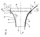
- Figure 1a shows a device 2 for applying individual reinforcing threads on a tubular layer in longitudinal section.
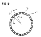
- the device 2 contains one circular positioning ring 4, which is a series of on a circumferential line has equidistant holes 6 (see also FIG. 1b, which is a cross section along the line Ib-Ib shown in FIG. 1a).
- FIG. 1b which is a cross section along the line Ib-Ib shown in FIG. 1a.
- Every single one Reinforcing thread 8 is from a radially outside of the positioning ring 4th located coil wound, which is attached to a creel, which the Positioning ring 4 concentrically surrounds (the coils and the creel are in 1a not shown, in this regard, however, reference is made to FIG. 4).
- the device 2 contains a rotationally symmetrical one funnel-shaped deflecting element 12.
- This has a single continuously tapered channel 14 with an annular inlet opening 16 and a smaller one annular outlet opening 18.
- the diameter of the inlet opening 16 corresponds to the clear diameter of the positioning ring.
- the surface 20 of the deflection element 12 becomes the individual reinforcing threads 8 guided. This becomes more precise in connection with the following figures explained.
- the entry angle ⁇ coincides with the entry angle ⁇
- Reinforcing threads 8 coincide with the longitudinal axis 10 of the positioning ring 4 and lie there between 40 ° and 100 °, preferably between 80 ° and 90 °.
- the deflecting element 12 is surrounded by the positioning ring 4 concentrically, so that the longitudinal axis 10 of the deflection element 12 with the longitudinal axis 10 of the Positioning ring 4 coincides. Furthermore, the deflecting element 12 for Positioning ring 4 axially aligned such that the holes 6 of the positioning ring 4th 'are immediately in front of the inlet opening 16 of the deflecting element 12, so that by the holes 6 directly from the radially outside to the radially inside reinforcing threads 8 can be guided into the inlet opening 16 of the deflecting element 12.
- the radially outside of the positioning ring 4 to the longitudinal axis 10 takes the angle ⁇ , is by the Deflection element 12 deflected so that an angle ⁇ to the outlet opening 18 Longitudinal axis 10 occupies.
- Figure 1b shows a section along the line Ib-Ib drawn in Figure 1a.
- a plurality of holes 6 are located on a circumferential line of the positioning ring 4 arranged.
- Two adjacent holes 6a and 6b in the positioning ring 4 each have the same distance D from one another.
- a reinforcing thread 8 is on the radially inner surface 20 of the Deflection element 12 guided, as already in connection with Figure 1a has been explained.
- FIG. 2 shows the radially inner surface 20 of a deflection element 12 in perspective view.
- the radially inner surface 20 is rotationally symmetrical to the longitudinal axis 10 and funnel-shaped.
- On the radially inner surface 20 run reinforcing threads 8.
- In the inlet opening 16 have any two adjacent reinforcing threads 8a and 8b the distance D from each other, which by the distance between the holes 6 in the positioning ring 4 is given at the Outlet opening 18 have any two adjacent reinforcing threads 8a, 8b Distance d from each other. All reinforcing threads 8 have both in the Entry opening 16 and in the exit opening 18 equidistant distances to each other.
- the "degree of merging" is determined by the Ratio r / R determined
- This shortest connecting line, along which a reinforcing thread 8 runs obviously determined by the fact that the reinforcing thread 8 on each imagined circular circumferential line 30 of the radially inner surface 20 is perpendicular. It follows that those extending from the inlet opening 16 to the outlet opening 18 Reinforcing threads 8 are only approximated to each other, but in each any imaginary circular circumferential line 30 equidistant distances to each other. Otherwise there would be at least one imaginary one circular circumferential line 30, on which not all reinforcing threads 8 are perpendicular would. In particular, the reinforcing threads 8 also take in the Exit opening 18 equidistant distances from each other.
- the funnel-shaped, rotationally symmetrical, radially inner surface 20 of the deflecting element 12 thus causes the reinforcing threads to be deflected be, as has been explained in connection with Figure 1.
- the radially inner surface 20 causes the distance D to be two neighboring reinforcing threads in the inlet opening 16 to the distance d two adjacent reinforcing threads in the outlet opening 18 is reduced. This everything is achieved without a single one on the radially inner surface 20 Guide channel must be provided for each individual reinforcing thread.
- the the only condition that must be met is that on the reinforcing threads 8 a Tensile load is exerted in the longitudinal direction of the deflecting element 12. furthermore should be the frictional forces between the reinforcing threads and the radially inner one Surface 20 should be as small as possible to ensure easy alignment of the threads enable.
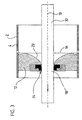
- FIG. 3 shows a device 2 for applying individual reinforcing threads a tubular layer in longitudinal section with a circular positioning ring 4 and a rotationally symmetrical deflection element.
- the device is basically constructed exactly as it was in connection with FIG. 1 has been explained, so that reference is made to the relevant description of the figures becomes.
- the radially inner one corresponds Surface 20 of the deflecting element 12 largely the surface that at Rotation of a quarter circle (or a quarter ellipse) about the longitudinal axis 10 of the Positioning ring 4 is created.
- the individual reinforcing threads 8 are in the The embodiment shown in Figure 3 at an entry angle to the longitudinal axis 10 of the positioning ring 4 from radially outside to radially inside, the between 80 ° and 100 °, preferably between 80 ° and 90 °.
- the individual reinforcing threads are deflected so that they on the Exit surface of the deflecting element 12 assume an exit angle that is between 0 ° and 10 °.
- a redirection over such a large angular range can by the deflection element 12 shown in Figure 3 on a very short Route can be made.
- the radial inside of the deflection element 12 starts from the Entry opening 16 concentrically guided a mandrel 32 (the direction of movement of the Doms 32 is indicated by the arrow).
- the diameter of the dome 32 corresponds largely the diameter of the outlet opening 18 of the deflection element 12.
- the deflection element 12 has an elastic one rotationally symmetrical centering sleeve 34, whose radially inner surface merges flush into the radially inner surface 20 of the deflection element 12.
- the Centering sleeve 34 allows the mandrel 32 even then through the radial To guide the interior of the deflecting element 12, if this with a thin tubular layer of polymeric material is covered.
- the elastic centering collar around the thickness of the tubular layer pressed radially outside and the reinforcing threads are on the radially outer Deposited surface of the tubular layer.
- Figure 4 shows a schematic representation of a production line for manufacturing a thread-reinforced tube blank consisting of several layers in the Longitudinal section.
- the mandrel 32 is from left to right in the direction of the arrow through the led individual processing stations.
- a first extruder 36 on the mandrel 32 a first tubular layer of polymeric material applied.
- an adhesive layer can be applied on the radially outer surface of the first tubular layer for example, an adhesive layer can be applied in a processing station 38.
- a first device 2a for applying individual Reinforcement threads 8 out.
- the device 2a is constructed exactly as it is has already been explained in connection with FIG. 3.
- the mandrel 32 is guided through the device 2a in exactly the same way as in FIG In connection with Figure 3 was explained.
- each coil 42 of the Coil gate 40 a brake.
- the brake can be applied to everyone Reinforcing thread acting tensile force are set, is preferred Traction selected between 5 N and 50 N, preferably between 0.6 N and 1 N, per reinforcement thread.
- an intermediate layer in a further processing station 40.
- the intermediate layer can be another layer of polymer material or an adhesive layer.
- the mandrel 32 is passed through a second extruder 44, in which the radially outer surface of the intermediate layer with a further layer polymeric material is covered.
- the tube blank is then completed and can be further processed in a manner known per se.
- the first device 2a and the associated first creel 40a can around the longitudinal axis of the cathedral coinciding with a certain one Rotate angular velocity.
- the second device 2b and the device assigned to it can Coil gate 40b also with a certain matching one Rotate the angular velocity around the longitudinal axis of the dome 32.
- the reinforcing threads on the intermediate layer also become spiral stored.
- the angular velocities of the devices 2a are preferably correct and 2b and the creel 40a and 40b and is the sense of rotation of the Devices 2a and 2b and the creel 40a and 40b opposite. In In this case, the pitch angle of the two spirals is the same, only their direction of rotation is opposite.
Landscapes
- Engineering & Computer Science (AREA)
- Mechanical Engineering (AREA)
- Moulding By Coating Moulds (AREA)
- Ropes Or Cables (AREA)
- Rigid Pipes And Flexible Pipes (AREA)
- Artificial Filaments (AREA)
- Yarns And Mechanical Finishing Of Yarns Or Ropes (AREA)
Description
- die Vorrichtung enthält einen Positionierring, der auf einer Umfangslinie mindestens eine Reihe von äquidistanten Löchern aufweist, durch die die Verstärkungsfäden in einem Eintrittswinkel zur Längsachse des Positionierringes von radial außen nach radial innen führbar sind,
- die Vorrichtung enthält ein rotationssymmetrisches, trichterförmiges Umlenkelement, das einen einzigen sich stetig verjüngenden Kanal mit einer ringförmigen Eintrittsfläche und einer kleineren ringförmigen Austrittsfläche umschließt und auf dessen rotationssymmetrischen radial inneren Oberfläche die Verstärkungsfäden führbar sind,
- an der Eintrittsfläche weist das Umlenkelement einen Eintrittswinkel α zur Längsachse des Umlenkelementes auf, der weitestgehend dem Eintrittswinkel der Verstärkungsfäden zur Längsachse des Positionierringes entspricht,
- an der Austrittsfläche weist das Umlenkelement einen Austrittswinkel zur Längsachse des Umlenkelementes auf, der ca. 0° bis 25°, vorzugsweise 0° bis 10°, beträgt,
- das Umlenkelement wird von dem Positionierring konzentrisch umfaßt und ist axial zum Positionierring derart ausgerichtet, daß radial durch die Löcher des Positionierringes geführte Verstärkungsfäden direkt in die Eintrittsfläche des Umlenkelementes führbar sind.
- durch jedes Loch des Positionierringes wird ein Verstärkungsfaden in einem Eintrittswinkel zur Längsachse des Positionierringes von radial außen nach radial innen geführt
- die Verstärkungsfäden werden auf die radial innere Oberfläche des
Umlenkelementes gelegt und durch das Umlenkelement von dem
Eintrittswinkel in einen weitestgehend axialen Verlauf umgelenkt, wobei die
Verstärkungsfäden ständig auf Zug belastet werden und ferner dadurch, daß
zur Herstellung eines fadenverstärkten Schlauchrohlings die folgenden
Verfahrensschritte durchgeführt werden:
- in einer ersten Verarbeitungsstation wird auf einem rotationssymmetrischen Dorn eine erste Schicht aus polymerem Werkstoff aufgebracht
- der mit der ersten Schicht beschichtete Dom wird ausgehend von der Eintrittsfläche des Umlenkelementes konzentrisch durch die Austrittsfläche des Umlenkelementes geführt, so daß sich die auf der radial inneren Oberfläche des Umlenkelementes befindlichen Verstärkungsfäden in äquidistanten Abständen auf der radial äußeren Oberfläche der ersten Schicht ablegen
- der mit der ersten Schicht beschichtete Dorn wird mindestens einer weiteren Verarbeitungsstation zugeführt, in der auf die erste Schicht eine weitere Schicht aus polymerem Werkstoff aufgebracht wird.
- Fig. 1a
- eine Vorrichtung zur Aufbringung einzelner Verstärkungsfäden auf eine schlauchförmige Schicht im Längsschnitt,
- Fig.1b
- eine Vorrichtung zur Aufbringung einzelner Verstärkungsfäden auf eine schlauchförmige Schicht im Querschnitt,
- Fig. 2
- ein rotationssymmetrisches trichterförmiges Umlenkelement in schematischer Ansicht,
- Fig. 3
- eine Vorrichtung zur Aufbringung einzelner Verstärkungsfäden auf eine schlauchförmige Schicht im Längsschnitt,
- Fig. 4
- eine Fertigungsstraße zur Herstellung eines fadenverstärkten, aus mehreren Schichten bestehenden Schlauchrohlings in schematicher Darstellung.
- 2
- Vorrichtung zur Aufbringung einzelner Verstärkungsfäden
- 4
- Positionierring
- 6
- Loch
- 8
- Verstärkungsfäden
- 10
- Lächsachse des Positionierringes
- 12
- Umlenkelement
- 14
- Kanal
- 16
- ringförmige Eintrittsöffnung
- 18
- ringförmige Austrittsöffnung
- 20
- radial innere Oberfläche
- 22, 24
- Tangente
- 26, 28
- Punkt
- 30
- kreisrunde Umfangslinie
- 32
- Dom
- 34
- Zentriermanschette
- 36
- erster Extruder
- 38
- Verarbeitungsstation
- 40
- Spulengatter
- 42
- Spule
- 40, 42
- Verarbeitungsstation
- 44
- zweiter Extruder
Claims (10)
- Vorrichtung (2) zur Aufbringung einzelner Verstärkungsfäden (8) auf eine schlauchförmige Schicht aus polymerem Werkstoff, die zu einem fadenverstärkten, aus mehreren Schichten bestehenden Schlauchrohling aus polymerem Werkstoff weiterverarbeitet wird, wobei
die Vorrichtung (2) folgende Merkmale aufweist:die Vorrichtung (2) enthält einen Positionierring (4), der auf einer Umfangslinie mindestens eine Reihe von äquidistanten Löchern (6) aufweist, wobei durch jedes Loch (6) ein Verstärkungsfaden (8) in einem Eintrittswinkel zur Längsachse des Positionierringes (4) von radial außen nach radial innen führbar istdie Vorrichtung (2) enthält ein rotationssymmetrisches trichterförmiges Umlenkelement (12), das einen einzigen sich stetig verjüngenden Kanal (14) mit einer ringförmigen Eintrittsöffnung (16) und einer kleineren ringförmigen Austrittsöffnung (18) umschließt und auf dessen radial innerer Oberfläche (20) die Verstärkungsfäden (8) führbar sindan der Eintrittsöffnung (16) weist das Umlenkelement einen Eintrittswinkel α zur Längsachse (10) des Umlenkelementes (12) auf, der weitestgehend dem Eintrittswinkel der Verstärkungsfäden (8) zur Längsachse (10) des Positionierringes (4) entsprichtan der Austrittsöffnung (18) weist das Umlenkelement (12) einen Austrittswinkel β zur Längsachse (10) des Umlenkelementes (12) auf, der zwischen 0° und 25°, vorzugsweise zwischen 0° und 10°, liegtdas Umlenkelement (12) wird von dem Positionierring (4) konzentrisch umfaßt und ist axial zum Positionierring (4) derart ausgerichtet, daß radial durch die Löcher (6) des Positionierringes (4) geführte Verstärkungsfäden (8) direkt in die Eintrittsöffnung (16) des Umlenkelementes (12) führbar sind. - Vorrichtung (2) nach Anspruch 1, dadurch gekennzeichnet, daß die Verstärkungsfäden (8) in einem Eintrittswinkel zwischen 40° und 100°, vorzugsweise zwischen 80° und 90°, zur Längsachse (10) des Positionierringes (4) durch die Löcher (6) des Positionierringes (4) geführt werden.
- Vorrichtung (2) nach Anspruch 2, dadurch gekennzeichnet, daß die radial innere Oberfläche (20) des Umlenkelementes (12) weitestgehend der Oberfläche entspricht, die bei der Rotation eines Viertelkreises bzw. einer Viertelellipse um die Längsachse des Positionierringes entsteht.
- Verfahren zur Herstellung eines fadenverstärkten, aus mehreren Schichten bestehenden Schlauchrohlings aus polymerem Werkstoff, mittels einer Vorrichtung nach einem der Ansprüche 1 bis 3, wobeidurch jedes Loch (6) des Positionierringes (4) ein Verstärkungsfaden (8) in einem Eintrittswinkel zur Längsachse (10) des Positionierringes (4) von radial außen nach radial innen geführt wirddie Verstärkungsfäden (8) auf die radial innere Oberfläche (20) des Umlenkelementes (12) gelegt werden und durch das Umlenkelement (12) von dem Eintrittswinkel in einen weitestgehend axialen Verlauf umgelenkt werden, wobei die Verstärkungsfäden (8) ständig auf Zug belastet werdenund ferner dadurch, daß folgende Verfahrensschritte durchgeführt werden: in einer ersten Verarbeitungsstation (36) wird auf einen rotationssymmetrischen Dom (32) eine erste Schicht aus polymerem Werkstoff aufgebrachtder mit der ersten Schicht beschichtete Dom (32) wird ausgehend von der Eintrittsöffnung (16) des Umlenkelementes (12) konzentrisch durch die Austrittsöffnung (18) des Umlenkelementes (12) geführt, so daß sich die auf der radial inneren Oberfläche (20) des Umlenkelementes (12) befindlichen Verstärkungsfäden in äquidistanten Abständen auf der radial äußeren Oberfläche der ersten Schicht ablegender mit der ersten Schicht beschichtete Dom (32) wird mindestens einer weiteren Verarbeitungsstation (44) zugeführt, in der auf die erste Schicht eine weitere Schicht aus polymerem Werkstoff aufgebracht wird.
- Verfahren nach Anspruch 4, dadurch gekennzeichnet, daß die erste Schicht auf der radial äußeren Oberfläche vor dem Ablegen der Verstärkungsfäden (8) auf dieser mit einer Haftschicht, z.B. in Form einer Gummilösung, versehen wird.
- Verfahren nach einem der Ansprüche 4 bis 5, dadurch gekennzeichnet, daß der Positionierring (4) und das Umlenkelement (6) mit der gleichen Winkelgeschwindigkeit um ihre Längsachse (10) rotieren, so daß die Verstärkungsfäden (8) spiralförmig auf der radial äußeren Oberfläche der ersten Schicht abgelegt werden.
- Verfahren nach einem der Ansprüche 4 bis 6, dadurch gekennzeichnet, daß die erste Schicht auf ihrer radial äußeren Oberfläche nach dem Ablegen der Verstärkungsfäden (8) auf dieser in einer Verarbeitungsstation (40) von einer Zwischenschicht abgedeckt wird und daß auf dieser Zwischenschicht mittels einer weiteren Umlenkvorrichtung (12) nach einem der Ansprüche 1 bis 3 weitere Verstärkungsfäden (8) wie folgt abgelegt werden:durch jedes Loch (6) des Positionierringes (4) der weiteren Vorrichtung (2) wird ein Verstärkungsfaden in einem Eintrittswinkel zur Längsachse des Positionierringes (4) von radial außen nach radial innen geführtdie Verstärkungsfäden (8) werden auf der radial inneren Oberfläche (20) des Umlenkelementes (12) der weiteren Vorrichtung (2) gelegt und werden durch das Umlenkelement (12) von dem Eintrittswinkel in einen weitestgehend axialen Verlauf umgelenkt, wobei die Verstärkungsfäden (8) ständig auf Zug belastet werdender mit der ersten Schicht und mit der Zwischenschicht beschichtete Dom (32) wird ausgehend von der Eintrittsöffnung (16) des Umlenkelementes (12) konzentrisch durch die Austrittsfläche (18) des Umlenkelementes (12) geführt, so daß sich die auf der radial inneren Oberfläche (20) des Umlenkelementes (12) befindlichen Verstärkungsfäden (8) in äquidistanten Abständen auf der radial äußeren Oberfläche der Zwischenschicht ablegen.
- Verfahren nach Anspruch 7, dadurch gekennzeichnet, daß der Positionierring (4) und das Umlenkelement (12) der ersten Vorrichtung (2a) und der zweiten Vorrichtung (2b) mit einer Winkelgeschwindigkeit um ihre Längsachse (10) rotieren, so daß die Verstärkungsfäden (8) spiralförmig auf der radial äußeren Oberfläche der ersten Schicht bzw. der Zwischenschicht abgelegt werden, wobei der Drehsinn des Positonierringes (4) und des Umlenkelementes (12) der zweiten Vorrichtung (2b) den Drehsinn des Positonierringes (4) und des Umlenkelementes (12) der ersten Vorrichtung (2a) entgegengesetzt ist und die Winkelgeschwindigkeiten, mit denen die beiden Vorrichtungen (2a, 2b) rotieren, vorzugsweise übereinstimmen.
- Verfahren nach einem der Ansprüche 4 bis 8, dadurch gekennzeichnet, daß der Radius des Dorns (32) weitestgehend dem Radius der Austrittsöffnung (18) der ersten Umlenkvorrichtung (12) bzw. der zweiten Umlenkvorrichtung (12) entspricht, sofern eine solche vorhanden ist.
- Verfahren nach einem der Ansprüche 4 bis 8, dadurch gekennzeichnet, daß die auf jeden Verstärkungsfaden (8) wirkende Zugbelastung zwischen 0,5 Nm und 5 Nm liegt.
Priority Applications (8)
| Application Number | Priority Date | Filing Date | Title |
|---|---|---|---|
| DE19846852A DE19846852C2 (de) | 1998-10-12 | 1998-10-12 | Vorrichtung zur Einarbeitung einzelner Verstärkungsfäden in einen Schlauchrohling und Verfahren zur Herstellung eines fadenverstärkten Schlauchrohlings mit Hilfe der Vorrichtung |
| HU9903468A HUP9903468A3 (en) | 1998-10-12 | 1999-10-11 | Apparatus formaking grafted fibres in the polymer containing inhalfpreparated hose and process for producing incured hose containing polymer and reinforced fibres, in more layers |
| JP11289484A JP2000141503A (ja) | 1998-10-12 | 1999-10-12 | 個々の補強糸をホ―ス半製品に加工する装置およびこの装置によって糸で補強されたホ―ス半製品を製造する方法 |
| AT99120586T ATE244129T1 (de) | 1998-10-12 | 1999-10-16 | Vorrichtung zur einarbeitung einzelner verstärkungsfäden in einem schlauchrohling und verfahren zur herstellung eines fadenverstärkten schlauchrohlings mit hilfe der vorrichtung |
| EP99120586A EP1099531B1 (de) | 1998-10-12 | 1999-10-16 | Vorrichtung zur Einarbeitung einzelner Verstärkungsfäden in einem Schlauchrohling und Verfahren zur Herstellung eines fadenverstärkten Schlauchrohlings mit Hilfe der Vorrichtung |
| ES99120586T ES2202983T3 (es) | 1998-10-12 | 1999-10-16 | Dispositivo para incorporar hilos de refuerzo individuales en un tubo flexible sin tratar y procedimiento para fabricar un tubo flexible sin tratar reforzado por hilos con la ayuda del dispositivo. |
| PT99120586T PT1099531E (pt) | 1998-10-12 | 1999-10-16 | Dispositivo para a incorporacao de fios de reforco individuais num tubo flexivel e procedimento para o fabrico de um tubo flexivel e procedimento para o fabrico de um tubo flexivel reforcado por fios com o auxilio do dispositivo |
| DE59906196T DE59906196D1 (de) | 1998-10-12 | 1999-10-16 | Vorrichtung zur Einarbeitung einzelner Verstärkungsfäden in einem Schlauchrohling und Verfahren zur Herstellung eines fadenverstärkten Schlauchrohlings mit Hilfe der Vorrichtung |
Applications Claiming Priority (2)
| Application Number | Priority Date | Filing Date | Title |
|---|---|---|---|
| DE19846852A DE19846852C2 (de) | 1998-10-12 | 1998-10-12 | Vorrichtung zur Einarbeitung einzelner Verstärkungsfäden in einen Schlauchrohling und Verfahren zur Herstellung eines fadenverstärkten Schlauchrohlings mit Hilfe der Vorrichtung |
| EP99120586A EP1099531B1 (de) | 1998-10-12 | 1999-10-16 | Vorrichtung zur Einarbeitung einzelner Verstärkungsfäden in einem Schlauchrohling und Verfahren zur Herstellung eines fadenverstärkten Schlauchrohlings mit Hilfe der Vorrichtung |
Publications (2)
| Publication Number | Publication Date |
|---|---|
| EP1099531A1 EP1099531A1 (de) | 2001-05-16 |
| EP1099531B1 true EP1099531B1 (de) | 2003-07-02 |
Family
ID=26049449
Family Applications (1)
| Application Number | Title | Priority Date | Filing Date |
|---|---|---|---|
| EP99120586A Expired - Lifetime EP1099531B1 (de) | 1998-10-12 | 1999-10-16 | Vorrichtung zur Einarbeitung einzelner Verstärkungsfäden in einem Schlauchrohling und Verfahren zur Herstellung eines fadenverstärkten Schlauchrohlings mit Hilfe der Vorrichtung |
Country Status (7)
| Country | Link |
|---|---|
| EP (1) | EP1099531B1 (de) |
| JP (1) | JP2000141503A (de) |
| AT (1) | ATE244129T1 (de) |
| DE (2) | DE19846852C2 (de) |
| ES (1) | ES2202983T3 (de) |
| HU (1) | HUP9903468A3 (de) |
| PT (1) | PT1099531E (de) |
Families Citing this family (4)
| Publication number | Priority date | Publication date | Assignee | Title |
|---|---|---|---|---|
| EP1253344B1 (de) | 2001-04-27 | 2005-11-09 | ContiTech Luftfedersysteme GmbH | Luftfederbalg |
| DE10229078B4 (de) * | 2002-06-28 | 2006-07-13 | Contitech Luftfedersysteme Gmbh | Vorrichtung zum Führen einzelner Verstärkungsfäden |
| DE10318545B3 (de) * | 2003-04-24 | 2004-08-05 | Contitech Luftfedersysteme Gmbh | Verfahren und Vorrichtung zur Herstellung gekrümmter, fadenverstärkter, schlauchförmiger Gebilde |
| JP4837962B2 (ja) * | 2005-09-20 | 2011-12-14 | 東洋ゴム工業株式会社 | 補強コード層の形成方法及び金具付きゴム製筒体 |
Family Cites Families (9)
| Publication number | Priority date | Publication date | Assignee | Title |
|---|---|---|---|---|
| US2093206A (en) * | 1935-06-27 | 1937-09-14 | Us Rubber Prod Inc | Cord covered tube and apparatus for applying cords to tubes, cores, and the like |
| FR1113671A (fr) * | 1953-11-28 | 1956-04-03 | Bayer Ag | Procédé de dispositif pour fabrication de tubes |
| BE547292A (de) * | 1955-05-10 | |||
| AU1827776A (en) * | 1976-09-30 | 1978-04-06 | Lundbergs Fab Ab N | Machine for manufacturing reinforced tubes |
| IT1146803B (it) * | 1981-09-10 | 1986-11-19 | Giovanni Schiapparelli | Tubetto isolante per uso elettrotecnico o tubetto di protezione in genere e sistema semplificato per la sua produzione |
| US4578024A (en) * | 1985-02-22 | 1986-03-25 | The Firestone Tire & Rubber Company | Coextrusion apparatus |
| DE3619981A1 (de) * | 1986-06-13 | 1987-12-17 | Freudenberg Carl Fa | Verfahren und vorrichtung zur herstellung eines fadenverstaerkten schlauches aus polymerem werkstoff |
| DE3824757A1 (de) * | 1987-07-25 | 1989-02-02 | Barmag Barmer Maschf | Verfahren zur verstaerkung von langgestreckten profilen |
| US5292472A (en) * | 1992-12-18 | 1994-03-08 | Bridgestone Corporation | Coextrusion apparatus and method with rotating cord guidance |
-
1998
- 1998-10-12 DE DE19846852A patent/DE19846852C2/de not_active Expired - Lifetime
-
1999
- 1999-10-11 HU HU9903468A patent/HUP9903468A3/hu unknown
- 1999-10-12 JP JP11289484A patent/JP2000141503A/ja not_active Withdrawn
- 1999-10-16 EP EP99120586A patent/EP1099531B1/de not_active Expired - Lifetime
- 1999-10-16 PT PT99120586T patent/PT1099531E/pt unknown
- 1999-10-16 AT AT99120586T patent/ATE244129T1/de not_active IP Right Cessation
- 1999-10-16 DE DE59906196T patent/DE59906196D1/de not_active Expired - Lifetime
- 1999-10-16 ES ES99120586T patent/ES2202983T3/es not_active Expired - Lifetime
Also Published As
| Publication number | Publication date |
|---|---|
| HU9903468D0 (en) | 1999-12-28 |
| JP2000141503A (ja) | 2000-05-23 |
| DE19846852A1 (de) | 2000-04-13 |
| HUP9903468A2 (hu) | 2001-01-29 |
| EP1099531A1 (de) | 2001-05-16 |
| ATE244129T1 (de) | 2003-07-15 |
| ES2202983T3 (es) | 2004-04-01 |
| PT1099531E (pt) | 2003-11-28 |
| HUP9903468A3 (en) | 2001-02-28 |
| DE19846852C2 (de) | 2001-07-26 |
| DE59906196D1 (de) | 2003-08-07 |
Similar Documents
| Publication | Publication Date | Title |
|---|---|---|
| DE2541084C3 (de) | Verfahren zur Herstellung einer im Wicklungsbereich freitragend ausgebildeten Spule | |
| DE69309027T2 (de) | Koextrusionsvorrichtung und Verfahren mit rotierender Kordelleitung | |
| DE2818575C3 (de) | Verfahren und Vorrichtung zur Herstellung von Kabelelementen mit optischen Fasern | |
| CH625459A5 (de) | ||
| EP0215337A2 (de) | Extrusionskopf | |
| DE3824757A1 (de) | Verfahren zur verstaerkung von langgestreckten profilen | |
| CH371586A (de) | Vorrichtung zur Herstellung von Reissverschlussgliederreihen | |
| DE102007029310A1 (de) | Wendelverteiler für eine Blasfolienanlage | |
| DE2818786C2 (de) | Verfahren zum Herstellen eines endlosen, ungezahnten Kraftübertragungsriemens | |
| DE19846852C2 (de) | Vorrichtung zur Einarbeitung einzelner Verstärkungsfäden in einen Schlauchrohling und Verfahren zur Herstellung eines fadenverstärkten Schlauchrohlings mit Hilfe der Vorrichtung | |
| EP0279321A2 (de) | Coextrusionskopf | |
| DE20307412U1 (de) | Werkzeug zur Extrusion eines rohrförmigen Schmelzestranges | |
| DE3721438A1 (de) | Maschine zur herstellung eines verstaerkten schlauchs | |
| DE69508105T2 (de) | Kunststoffrohr, extrusionsdüse und verfahren zur herstellung solche kunststoffröhren | |
| DE2456440B2 (de) | Fadenspeichervorrichtung | |
| DE3206636A1 (de) | Vorrichtung zum herstellen von metallschnueren | |
| EP1426163A2 (de) | Werkzeug zur Extrusion eines rohrförmigen Schmelzestranges | |
| DE4339671C2 (de) | Vorrichtung zum Herstellen eines schlauch- oder rohrförmigen Hohlstranges aus thermoplastischem Kunststoff | |
| DE2104690A1 (de) | Filterrohr insbes. für Brunnen und Verfahren und Vorrichtung zur Herstellung desselben | |
| DE2808079C2 (de) | Vorrichtung zur Herstellung eines Vlieses von unbestimmter Länge aus einem thermoplastischen Kunstharzmaterial | |
| DE3704698A1 (de) | Coextrusionskopf | |
| EP0876898B1 (de) | Vorrichtung zur Herstellung eines Relining-Schlauchs | |
| DE10210847B4 (de) | Verteilerplatten zum Verteilen von Schmelzen vom Zentrum auf die Einzelschichten bei Coextrusionsblasköpfen | |
| DE102010051910A1 (de) | Dreheinführungsvorrichtung | |
| DE1218232C2 (de) | Schlauch mit Kunststoffwendel und Verfahren sowie Vorrichtung zu seiner Herstellung |
Legal Events
| Date | Code | Title | Description |
|---|---|---|---|
| PUAI | Public reference made under article 153(3) epc to a published international application that has entered the european phase |
Free format text: ORIGINAL CODE: 0009012 |
|
| AK | Designated contracting states |
Kind code of ref document: A1 Designated state(s): AT BE CH CY DE DK ES FI FR GB GR IE IT LI LU MC NL PT SE |
|
| AX | Request for extension of the european patent |
Free format text: AL;LT;LV;MK;RO;SI |
|
| RAP1 | Party data changed (applicant data changed or rights of an application transferred) |
Owner name: CONTITECH LUFTFEDERSYSTEME GMBH |
|
| 17P | Request for examination filed |
Effective date: 20011116 |
|
| AKX | Designation fees paid |
Free format text: AT BE CH CY DE DK ES FI FR GB GR IE IT LI LU MC NL PT SE |
|
| GRAH | Despatch of communication of intention to grant a patent |
Free format text: ORIGINAL CODE: EPIDOS IGRA |
|
| GRAH | Despatch of communication of intention to grant a patent |
Free format text: ORIGINAL CODE: EPIDOS IGRA |
|
| GRAA | (expected) grant |
Free format text: ORIGINAL CODE: 0009210 |
|
| AK | Designated contracting states |
Designated state(s): AT BE CH CY DE DK ES FI FR GB GR IE IT LI LU MC NL PT SE |
|
| PG25 | Lapsed in a contracting state [announced via postgrant information from national office to epo] |
Ref country code: NL Free format text: LAPSE BECAUSE OF FAILURE TO SUBMIT A TRANSLATION OF THE DESCRIPTION OR TO PAY THE FEE WITHIN THE PRESCRIBED TIME-LIMIT Effective date: 20030702 Ref country code: FI Free format text: LAPSE BECAUSE OF FAILURE TO SUBMIT A TRANSLATION OF THE DESCRIPTION OR TO PAY THE FEE WITHIN THE PRESCRIBED TIME-LIMIT Effective date: 20030702 |
|
| REG | Reference to a national code |
Ref country code: GB Ref legal event code: FG4D Free format text: NOT ENGLISH |
|
| REG | Reference to a national code |
Ref country code: CH Ref legal event code: EP |
|
| REG | Reference to a national code |
Ref country code: IE Ref legal event code: FG4D Free format text: GERMAN |
|
| REF | Corresponds to: |
Ref document number: 59906196 Country of ref document: DE Date of ref document: 20030807 Kind code of ref document: P |
|
| PG25 | Lapsed in a contracting state [announced via postgrant information from national office to epo] |
Ref country code: GR Free format text: LAPSE BECAUSE OF FAILURE TO SUBMIT A TRANSLATION OF THE DESCRIPTION OR TO PAY THE FEE WITHIN THE PRESCRIBED TIME-LIMIT Effective date: 20031002 Ref country code: DK Free format text: LAPSE BECAUSE OF FAILURE TO SUBMIT A TRANSLATION OF THE DESCRIPTION OR TO PAY THE FEE WITHIN THE PRESCRIBED TIME-LIMIT Effective date: 20031002 |
|
| PG25 | Lapsed in a contracting state [announced via postgrant information from national office to epo] |
Ref country code: LU Free format text: LAPSE BECAUSE OF NON-PAYMENT OF DUE FEES Effective date: 20031016 Ref country code: CY Free format text: LAPSE BECAUSE OF FAILURE TO SUBMIT A TRANSLATION OF THE DESCRIPTION OR TO PAY THE FEE WITHIN THE PRESCRIBED TIME-LIMIT Effective date: 20031016 Ref country code: AT Free format text: LAPSE BECAUSE OF NON-PAYMENT OF DUE FEES Effective date: 20031016 |
|
| REG | Reference to a national code |
Ref country code: SE Ref legal event code: TRGR |
|
| PG25 | Lapsed in a contracting state [announced via postgrant information from national office to epo] |
Ref country code: MC Free format text: LAPSE BECAUSE OF NON-PAYMENT OF DUE FEES Effective date: 20031031 Ref country code: LI Free format text: LAPSE BECAUSE OF NON-PAYMENT OF DUE FEES Effective date: 20031031 Ref country code: CH Free format text: LAPSE BECAUSE OF NON-PAYMENT OF DUE FEES Effective date: 20031031 |
|
| GBT | Gb: translation of ep patent filed (gb section 77(6)(a)/1977) |
Effective date: 20031025 |
|
| NLV1 | Nl: lapsed or annulled due to failure to fulfill the requirements of art. 29p and 29m of the patents act | ||
| REG | Reference to a national code |
Ref country code: ES Ref legal event code: FG2A Ref document number: 2202983 Country of ref document: ES Kind code of ref document: T3 |
|
| ET | Fr: translation filed | ||
| PLBE | No opposition filed within time limit |
Free format text: ORIGINAL CODE: 0009261 |
|
| STAA | Information on the status of an ep patent application or granted ep patent |
Free format text: STATUS: NO OPPOSITION FILED WITHIN TIME LIMIT |
|
| REG | Reference to a national code |
Ref country code: CH Ref legal event code: PL |
|
| 26N | No opposition filed |
Effective date: 20040405 |
|
| PGFP | Annual fee paid to national office [announced via postgrant information from national office to epo] |
Ref country code: GB Payment date: 20101021 Year of fee payment: 12 Ref country code: IT Payment date: 20101026 Year of fee payment: 12 |
|
| PGFP | Annual fee paid to national office [announced via postgrant information from national office to epo] |
Ref country code: PT Payment date: 20111011 Year of fee payment: 13 Ref country code: SE Payment date: 20111021 Year of fee payment: 13 Ref country code: BE Payment date: 20111013 Year of fee payment: 13 Ref country code: IE Payment date: 20111020 Year of fee payment: 13 Ref country code: ES Payment date: 20111026 Year of fee payment: 13 |
|
| REG | Reference to a national code |
Ref country code: PT Ref legal event code: MM4A Free format text: LAPSE DUE TO NON-PAYMENT OF FEES Effective date: 20130416 |
|
| BERE | Be: lapsed |
Owner name: *CONTITECH LUFTFEDERSYSTEME G.M.B.H. Effective date: 20121031 |
|
| GBPC | Gb: european patent ceased through non-payment of renewal fee |
Effective date: 20121016 |
|
| REG | Reference to a national code |
Ref country code: IE Ref legal event code: MM4A |
|
| PG25 | Lapsed in a contracting state [announced via postgrant information from national office to epo] |
Ref country code: SE Free format text: LAPSE BECAUSE OF NON-PAYMENT OF DUE FEES Effective date: 20121017 Ref country code: BE Free format text: LAPSE BECAUSE OF NON-PAYMENT OF DUE FEES Effective date: 20121031 Ref country code: IE Free format text: LAPSE BECAUSE OF NON-PAYMENT OF DUE FEES Effective date: 20121016 Ref country code: GB Free format text: LAPSE BECAUSE OF NON-PAYMENT OF DUE FEES Effective date: 20121016 |
|
| PG25 | Lapsed in a contracting state [announced via postgrant information from national office to epo] |
Ref country code: IT Free format text: LAPSE BECAUSE OF NON-PAYMENT OF DUE FEES Effective date: 20121016 Ref country code: PT Free format text: LAPSE BECAUSE OF NON-PAYMENT OF DUE FEES Effective date: 20130416 |
|
| REG | Reference to a national code |
Ref country code: ES Ref legal event code: FD2A Effective date: 20140115 |
|
| PG25 | Lapsed in a contracting state [announced via postgrant information from national office to epo] |
Ref country code: ES Free format text: LAPSE BECAUSE OF NON-PAYMENT OF DUE FEES Effective date: 20121017 |
|
| REG | Reference to a national code |
Ref country code: FR Ref legal event code: PLFP Year of fee payment: 17 |
|
| REG | Reference to a national code |
Ref country code: FR Ref legal event code: PLFP Year of fee payment: 18 |
|
| PGFP | Annual fee paid to national office [announced via postgrant information from national office to epo] |
Ref country code: DE Payment date: 20161031 Year of fee payment: 18 Ref country code: FR Payment date: 20161020 Year of fee payment: 18 |
|
| REG | Reference to a national code |
Ref country code: DE Ref legal event code: R231 Ref document number: 59906196 Country of ref document: DE |
|
| PG25 | Lapsed in a contracting state [announced via postgrant information from national office to epo] |
Ref country code: DE Free format text: LAPSE BECAUSE OF THE APPLICANT RENOUNCES Effective date: 20170306 |
|
| REG | Reference to a national code |
Ref country code: FR Ref legal event code: ST Effective date: 20180629 |
|
| PG25 | Lapsed in a contracting state [announced via postgrant information from national office to epo] |
Ref country code: FR Free format text: LAPSE BECAUSE OF NON-PAYMENT OF DUE FEES Effective date: 20171031 |