EP1098313A2 - Data reproduction apparatus and method with improved performance by adjusting filter coefficients of equalizer - Google Patents
Data reproduction apparatus and method with improved performance by adjusting filter coefficients of equalizer Download PDFInfo
- Publication number
- EP1098313A2 EP1098313A2 EP00309356A EP00309356A EP1098313A2 EP 1098313 A2 EP1098313 A2 EP 1098313A2 EP 00309356 A EP00309356 A EP 00309356A EP 00309356 A EP00309356 A EP 00309356A EP 1098313 A2 EP1098313 A2 EP 1098313A2
- Authority
- EP
- European Patent Office
- Prior art keywords
- sampling data
- level
- data
- equalizer
- positive
- Prior art date
- Legal status (The legal status is an assumption and is not a legal conclusion. Google has not performed a legal analysis and makes no representation as to the accuracy of the status listed.)
- Withdrawn
Links
Images






Classifications
-
- G—PHYSICS
- G11—INFORMATION STORAGE
- G11B—INFORMATION STORAGE BASED ON RELATIVE MOVEMENT BETWEEN RECORD CARRIER AND TRANSDUCER
- G11B20/00—Signal processing not specific to the method of recording or reproducing; Circuits therefor
- G11B20/10—Digital recording or reproducing
-
- G—PHYSICS
- G11—INFORMATION STORAGE
- G11B—INFORMATION STORAGE BASED ON RELATIVE MOVEMENT BETWEEN RECORD CARRIER AND TRANSDUCER
- G11B20/00—Signal processing not specific to the method of recording or reproducing; Circuits therefor
- G11B20/10—Digital recording or reproducing
- G11B20/10009—Improvement or modification of read or write signals
-
- G—PHYSICS
- G11—INFORMATION STORAGE
- G11B—INFORMATION STORAGE BASED ON RELATIVE MOVEMENT BETWEEN RECORD CARRIER AND TRANSDUCER
- G11B20/00—Signal processing not specific to the method of recording or reproducing; Circuits therefor
- G11B20/10—Digital recording or reproducing
- G11B20/10009—Improvement or modification of read or write signals
- G11B20/10046—Improvement or modification of read or write signals filtering or equalising, e.g. setting the tap weights of an FIR filter
- G11B20/10055—Improvement or modification of read or write signals filtering or equalising, e.g. setting the tap weights of an FIR filter using partial response filtering when writing the signal to the medium or reading it therefrom
- G11B20/10101—PR2 or PR(1,2,1), i.e. partial response class 2, polynomial (1+D)2=1+2D+D2
-
- G—PHYSICS
- G11—INFORMATION STORAGE
- G11B—INFORMATION STORAGE BASED ON RELATIVE MOVEMENT BETWEEN RECORD CARRIER AND TRANSDUCER
- G11B20/00—Signal processing not specific to the method of recording or reproducing; Circuits therefor
- G11B20/10—Digital recording or reproducing
- G11B20/10009—Improvement or modification of read or write signals
- G11B20/10268—Improvement or modification of read or write signals bit detection or demodulation methods
- G11B20/10287—Improvement or modification of read or write signals bit detection or demodulation methods using probabilistic methods, e.g. maximum likelihood detectors
- G11B20/10296—Improvement or modification of read or write signals bit detection or demodulation methods using probabilistic methods, e.g. maximum likelihood detectors using the Viterbi algorithm
-
- H—ELECTRICITY
- H03—ELECTRONIC CIRCUITRY
- H03H—IMPEDANCE NETWORKS, e.g. RESONANT CIRCUITS; RESONATORS
- H03H21/00—Adaptive networks
- H03H21/0012—Digital adaptive filters
-
- H—ELECTRICITY
- H04—ELECTRIC COMMUNICATION TECHNIQUE
- H04L—TRANSMISSION OF DIGITAL INFORMATION, e.g. TELEGRAPHIC COMMUNICATION
- H04L1/00—Arrangements for detecting or preventing errors in the information received
- H04L1/004—Arrangements for detecting or preventing errors in the information received by using forward error control
- H04L1/0045—Arrangements at the receiver end
- H04L1/0054—Maximum-likelihood or sequential decoding, e.g. Viterbi, Fano, ZJ algorithms
-
- G—PHYSICS
- G11—INFORMATION STORAGE
- G11B—INFORMATION STORAGE BASED ON RELATIVE MOVEMENT BETWEEN RECORD CARRIER AND TRANSDUCER
- G11B20/00—Signal processing not specific to the method of recording or reproducing; Circuits therefor
- G11B20/10—Digital recording or reproducing
- G11B20/10009—Improvement or modification of read or write signals
- G11B20/10046—Improvement or modification of read or write signals filtering or equalising, e.g. setting the tap weights of an FIR filter
- G11B20/10203—Improvement or modification of read or write signals filtering or equalising, e.g. setting the tap weights of an FIR filter baseline correction
-
- H—ELECTRICITY
- H04—ELECTRIC COMMUNICATION TECHNIQUE
- H04L—TRANSMISSION OF DIGITAL INFORMATION, e.g. TELEGRAPHIC COMMUNICATION
- H04L25/00—Baseband systems
- H04L25/02—Details ; arrangements for supplying electrical power along data transmission lines
- H04L25/03—Shaping networks in transmitter or receiver, e.g. adaptive shaping networks
- H04L25/03006—Arrangements for removing intersymbol interference
- H04L2025/0335—Arrangements for removing intersymbol interference characterised by the type of transmission
- H04L2025/03356—Baseband transmission
- H04L2025/03369—Partial response
-
- H—ELECTRICITY
- H04—ELECTRIC COMMUNICATION TECHNIQUE
- H04L—TRANSMISSION OF DIGITAL INFORMATION, e.g. TELEGRAPHIC COMMUNICATION
- H04L25/00—Baseband systems
- H04L25/02—Details ; arrangements for supplying electrical power along data transmission lines
- H04L25/03—Shaping networks in transmitter or receiver, e.g. adaptive shaping networks
- H04L25/03006—Arrangements for removing intersymbol interference
- H04L2025/03433—Arrangements for removing intersymbol interference characterised by equaliser structure
- H04L2025/03439—Fixed structures
- H04L2025/03445—Time domain
- H04L2025/03471—Tapped delay lines
- H04L2025/03477—Tapped delay lines not time-recursive
Definitions
- the present invention relates to the field of data reproduction, and more particularly, to a data reproduction apparatus and method with optimum performance by adjusting filter coefficients for an equalizer to minimize a level error in detecting data.
- PRML partial response maximum likelihood
- Viterbi decoders have a predetermined reference level for use in detecting an error value of data. To match the level of input data of a Viterbi decoder to the predetermined reference level, filter tap coefficients of an equalizer connected in front of the Viterbi detector are adjusted to output data whose level matches the reference level of the Viterbi detector.
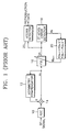
- Figure 1 illustrates a coefficient adaptation method of a conventional equalizer.
- An analog-to-digital converter (ADC) 10 samples an input radio frequency (RF) signal, and an asymmetry compensator 12 and an adder 14 correct for asymmetry or a DC offset component of the sample RF signal and provides the result to an equalizer 16.
- a 3T level error detector 18 detects a difference, i.e., error (e k ), between a reference value and the minimum pit (or mark) level, which corresponds to 3T (where T is a pit interval) in a conventional digital versatile disc (DVD) or compact disc (CD)), output from the equalizer 16 which is constituted of a finite impulse response (FIR) filter.
- FIR finite impulse response
- a filter coefficient adjuster 20 determines that the minimum pit level is larger than the reference value.
- the filter coefficient adjuster 20 provides the equalizer 16 with a filter coefficient W k+1 , which is adjusted to decrement a filter coefficient K b and increment a filter coefficient K a , to decrease the minimum pit level output from the equalizer 16.
- the filter coefficient adjuster 20 determines that the minimum pit level is smaller than the reference value.
- the filter coefficient adjuster 20 provides the equalizer 16 with the filter coefficient W k+1 , which is adjusted to increment the filter coefficient K a and decrement the filter coefficient K b , to increase the minimum pit level output from the equalizer 16.
- the minimum pit level is adjusted to an appropriate level in the above manner, so that the performance of the Viterbi detector 22 is enhanced.
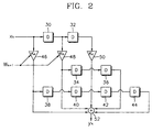
- Figure 2 illustrates the structure of the equalizer 16.
- x k indicates data input to the equalizer 16
- y k indicates data output from the equalizer 16
- W k+1 indicates the filter coefficient for the equalizer 16 after coefficient adaptation.
- Reference numerals 30, 32, 34, 36, 38, 40, 42 and 44 denote delays
- reference numerals 46, 48 and 50 denote coefficient multipliers
- reference numeral 52 denotes an adder.
- the coefficient adaptation in the conventional equalizer ensures the improvement of reproduction performance, by adjusting filter coefficients.
- the conventional equalizer cannot be adopted when the coefficients of the equalizer asymmetrically vary due to tangential tilting.
- a data reproduction apparatus including a data detector for detecting data based on partial response maximum likelihood (PRML), the apparatus comprising: an equalizer comprising a digital filter; a level error detector for extracting a level of the output value of the equalizer based on a reference level set in the data detector, and detecting a level error between the level of the output value and a predetermined reference value; a coefficient bank for storing filter coefficients of the equalizer; and a coefficient selector for selecting the filter coefficients of the equalizer from the coefficient bank such that the level error is minimized.
- PRML partial response maximum likelihood
- the error detector predetermines at least one reference value corresponding to zero level, positive and negative middle levels, and positive and negative maximum levels, which are classified depending on the partial response (PR) type of the data detector and detects the levels from the output value of the equalizer, and outputs the level error corresponding to differences between the detected levels and corresponding reference values.
- PR partial response
- the error detector may determine whether or not the product of two successive sampling data output from the equalizer is less than 0, determines which one of the sampling data is greater than 0 if the product of the two successive sampling data is less than 0, determines the sampling data greater than 0 as the positive middle level, and the sampling data less than 0 as the negative middle level, and detects level errors corresponding to the differences between the values of the sampling data determined as the positive and negative middle levels, and corresponding reference values.
- the error detector may determine whether or not all three successive sampling data output from the equalizer are greater than a predetermined threshold value, determines the middle sampling data as the positive maximum level if all of the three successive sampling data are greater than the predetermined threshold value, and determines the middle sampling data as the negative maximum level if all of the three successive sampling data are less than the predetermined threshold value, and detects level errors corresponding to the differences between the values of the sampling data determined as the positive and negative maximum levels, and corresponding reference values.
- the error detector may determine whether or not the product of two successive sampling data output from the equalizer is less than or equal to 0, and determines the sampling data whose absolute value is less than the absolute value of the other sampling data as the zero level, and detects the difference between the value of the sampling data determined as the zero level and a corresponding reference value.
- the error detector may determine whether the product of two successive sampling data output from the equalizer is less than or equal to 0, compares the absolute values of the two successive data if the product of two successive sampling data output from the equalizer is less than or equal to 0, determines the latter of the two successive sampling data, and the sampling data preceding the two successive sampling data to be the positive and negative middle levels, respectively, if the absolute value of the latter of the two successive sampling data is greater than that of the other sampling data, determines the sampling data preceding the two successive sampling data, and the sampling data following the two successive sampling data to be the positive and negative middle levels, respectively, if the absolute value of the former of the two successive sampling data is and greater than or equal to the other sampling data, and detects level errors corresponding to the differences between the values of the sampling data determined as the negative and positive middle levels, and corresponding reference values.
- the coefficient bank may store the filter coefficients of the equalizer, which are adapted according to the servo status and the degree of defocusing and tangential tilting.
- the coefficient selector may select coefficients stored in the coefficient bank according to a coefficient change request signal input from the outside to replace the filter coefficients of the equalizer with the selected coefficients, checks the level error output from the level error detector, and determines the coefficients which minimize the level error to be the final filter coefficients of the equalizer.
- a data reproduction apparatus including a data detector for detecting data based on partial response maximum likelihood (PRML), the apparatus comprising: an equalizer comprising a digital filter; a level error detector for extracting a level of the output value of the equalizer based on a reference level set in the data detector, and detecting a level error between the level of the output value and a predetermined reference value; and a coefficient adapter for adapting filter coefficients of the equalizer such that a difference between the level error and a target level error is minimized.
- PRML partial response maximum likelihood
- the error detector predetermines at least one reference value corresponding to zero level, positive and negative middle levels, and positive and negative maximum levels, which are classified depending on the partial response (PR) type of the data detector and detects the levels from the output value of the equalizer, and outputs the level error corresponding to differences between the detected levels and corresponding reference values.
- PR partial response
- the error detector may determine whether or not the product of two successive sampling data output from the equalizer is less than 0, determines which one of the sampling data is greater than 0 if the product of the two successive sampling data is less than 0, determines the sampling data greater than 0 as the positive middle level, and the sampling data less than 0 as the negative middle level, and detects level errors corresponding to the differences between the values of the sampling data determined as the positive and negative middle levels, and corresponding reference values.
- the error detector may determine whether or not all three successive sampling data output from the equalizer are greater than a predetermined threshold value, determines the middle sampling data as the positive maximum level if all of the three successive sampling data are greater than the predetermined threshold value, and determines the middle sampling data as the negative maximum level if all of the three successive sampling data are less than the predetermined threshold value, and detects level errors corresponding to the differences between the values of the sampling data determined as the positive and negative maximum levels, and corresponding reference values.
- the error detector may determine whether or not the product of two successive sampling data output from the equalizer is less than or equal to 0, and determines the sampling data whose absolute value is less than the absolute value of the other sampling data as the zero level, and detects the difference between the value of the sampling data determined as the zero level and a corresponding reference value.
- the error detector may determine whether the product of two successive sampling data output from the equalizer is less than or equal to 0, compares the absolute values of the two successive data if the product of two successive sampling data output from the equalizer is less than or equal to 0, determines the latter of the two successive sampling data, and the sampling data preceding the two successive sampling data to be the positive and negative middle levels, respectively, if the absolute value of the latter of the two successive sampling data is greater than that of the other sampling data, determines the sampling data preceding the two successive sampling data, and the sampling data following the two successive sampling data to be the positive and negative middle levels, respectively, if the absolute value of the former of the two successive sampling data is and greater than or equal to the other sampling data, and detects level errors corresponding to the differences between the values of the sampling data determined as the negative and positive middle levels, and corresponding reference values.
- the data reproduction apparatus may further comprise a defocus/tilt detector for detecting the servo status by monitoring variations of the adaptive filter coefficients of the equalizer.
- the defocus/tilt detector preferably determines a state where both side tap coefficients around the central tap coefficient of the equalizer increase to be a state of defocus, and outputs a defocus signal.
- the defocus/tilt detector may determine a state where one side tap coefficient with respect to the central tap coefficient of the equalizer increases while the opposite side tap coefficient decreases to be a state of tangential tilting, and outputs a tangential tilt signal.
- the defocus/tilt detector may determine the direction of the tangential tilting according to which side tap coefficient increases or decreases with respect to the central tap coefficient.
- a data reproduction method capable of improving the performance of a data detector for detecting data based on partial response maximum likelihood (PRML) by adjusting filter coefficients of an equalizer comprising a digital filter, connected before the data detector, the method comprising the steps of: (a) extracting a level of the output data of the equalizer based on a reference level set in the data detector, and detecting a level error between the level of the output data and a predetermined reference value; and (b) adjusting the filter coefficients of the equalizer such that the level error is minimized.
- PRML partial response maximum likelihood
- step (a) at least one reference value corresponding to zero level, positive and negative middle levels, or positive and negative maximum levels, which are classified depending on the partial response (PR) type of the data detector is predetermined, a level of the output value of the equalizer is detected based on the classified levels, and the level error is detected corresponding to differences between the detected levels and corresponding reference values.
- PR partial response
- step (b) the filter coefficients of the equalizer may be adapted according to the servo status and the degree of defocusing and tangential tilting.
- step (b) the filter coefficients of the equalizer may be changed according to a coefficient change request signal input from the outside, and the level error is continuously checked to determine the coefficients which minimize the level error as the final filter coefficients of the equalizer.
- step (b) the filter coefficients of the equalizer may be adapted such that a difference between the level error and a target level error is minimized.
- the data reproduction method may further comprise (c) monitoring the adaptive filter coefficients of the equalizer and determining the servo status according to the variations of the adaptive filter coefficients.
- step (c) when one side tap coefficient with respect to the central tap coefficient increases while the opposite side tap coefficient decreases, the state may be determined to be a state of tangential tilting.
- step (c) the direction of the tangential tilting may be detected according to which side tap coefficient increases or decreases.
- FIG. 3 A preferred embodiment of a data reproduction apparatus according to the present invention is shown in Figure 3.
- an analog-to-digital converter (ADC) 100, an asymmetry compensator 102, an adder 104, an equalizer 106 and a Viterbi detector 114 are the same as those shown in Figure 1. Thus, a description of the operation of these elements won't be repeated here.
- the Viterbi detector 114 is a data detector based on partial response maximum likelihood (PRML).
- a level error detector 108 has predetermined reference values for positive and negative middle and maximum levels.
- the level error detector 108 detects positive and negative middle and maximum levels from an input signal y k by detection methods, which will be described with reference to Figures 4 and 5, and outputs a level error e k for each detected level with respect to the corresponding reference values.
- the Viterbi decoder 114 is a PR(a,b,b,a) type
- the level error detector 108 has predetermined reference values for positive and negative middle and maximum levels as well as zero level.
- the level error detector 108 detects those levels from the input signal y k by detection methods, which will be described with reference to Figures 5, 6 and 7, and outputs a level error e k for each detected level with respect to the corresponding reference values.
- a coefficient bank 112 which stores a plurality of coefficient values for the equalizer 106, outputs a coefficient value W k+1 according to selection by a coefficient selector 110, as a filter tap coefficient value for the equalizer 106.
- the coefficient selector 110 selects coefficients stored in the coefficient bank 112, and changes the tap filter coefficients of the equalizer 106.
- the coefficient selector 110 checks the level error e k output from the level error detector 108 and sets the coefficient with the minimum level error as the final filter tap coefficient for the equalizer 106.
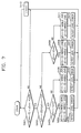
- Figure 4 is a flowchart illustrating a preferred embodiment of an error detection method with the positive and negative middle levels extracted from the output signal y k of the equalizer 106 when a PR(a,b,a) type Viterbi decoder is adopted.
- step S101 it is determined whether the product of two successive sampling data y(t+n-1) and y(t+n) is less than 0. If yes, it is determined which one of the two sampling data, for example, y(t+n-1), is greater than 0 (step S102). One of the sampling data, which is greater than 0, is determined to be a positive middle level, and the other sampling data which is less than 0 is determined to be a negative middle level. That is, if it is determined in step S103 that y(t+n-1) is greater than 0, y(t+n-1) is determined as the positive middle level, and y(t+n) is determined as the negative middle level (step S103).
- step S104 a level error corresponding to a difference between the positive middle level, the value of data y(t+n-1), and a corresponding reference value, and a level error corresponding to a difference between a corresponding reference value and the negative middle level, the value of data y(t+n), are detected (step S104).
- step S102 If it is determined in step S102 that the sampling data y(t+n-1) is less than 0, y(t+n-1) is determined to be a negative middle level and y(t+n) is determined to be a positive middle level (step S105).
- step S106 a level error corresponding to a difference between the negative middle level, the value of data y(t+n) and a corresponding reference value, and a level error corresponding to a difference between a corresponding reference value and the positive middle level, the value of data y(t+n-1), are detected.
- steps S101 through S106 are reiterated to determine positive and negative middle levels for the next sample (step S107).
- Figure 5 is a flowchart illustrating a preferred embodiment of an error detection method using the positive and negative maximum levels extracted from the output signal y k of the equalizer 106 when a PR(a,b,a) or PR(a,b,b,a) type Viterbi decoder is adopted.
- step S201 It is determined whether all of three successive sampling data y(t+n-2), y(t+n-1) and y(t+n) are greater than a threshold value Th (step S201). If yes, the middle sampling data y(t+n-1) is determined to be a positive maximum level (step S202). Next, a level error corresponding to a difference between the positive maximum level, the value of y(t+n-1), and a corresponding reference value is detected (step S203).
- step S201 If, in step S201, any of the sampling data y(t+n-2), y(t+n-1) and y(t+n) is less than the threshold value Th, it is determined whether all of the three successive data y(t+n-2), y(t+n-1) and y(t+n) is less than the threshold value Th (step S204). If yes, the middle sampling data y(t+n-1) is determined to be a negative maximum level (step S205). Next, a level error corresponding to a difference between the negative maximum level, the value of y(t+n-1), and a corresponding reference value is detected (step S206).
- step S204 If, in step S204, at least one of the successive sampling data y(t+n-2), y(t+n-1) and y(t+n) is not less than the threshold value Th, or if steps S203 and S206 are completed, steps S201 through S206 are reiterated to determine positive and negative maximum levels for the next sample (step S207).
- Figure 6 is a flowchart illustrating a preferred embodiment of an error detection method using the zero level extracted from the output signal y k of the equalizer 106 when a PR(a,b,b,a) type Viterbi decoder is adopted.
- step S301 it is determined whether the product of the successive sampling data y(t+n-1) and y(t+n) is less than or equal to 0 (step S301). Then, the absolute values of the sampling data y(t+n-1) and y(t+n) are compared (step S302). If the absolute value of the leading sampling data y(t+n-1) is less than or equal to the absolute value of the other sampling data y(t+n), the sampling data y(t+n-1) is determined to be the zero level (step S303). Then, a level error corresponding to the difference between the data value of y(t+n-1) and a reference value is detected (step S304).
- step S302 If it is determined in step S302 that the absolute value of the sampling data y(t+n) is smaller than that of the leading sampling data y(t+n-1), the sampling data y(t+n) is determined to be the zero level (step S305). Then, a level error corresponding to the difference between the data value of the sampling data y(t+n) and the reference value is detected (step S306). If the product of the two sampling data y(t+n-1) and y(t+n) is greater than 0, or if the step S304 or S306 is completed, steps S301 through S306 are reiterated to detect the zero level for the next sample (step S307).
- Figure 7 is a flowchart illustrating a preferred embodiment of an error detection method using the positive and negative minimum levels extracted from the output signal y k of the equalizer 106 when a PR(a,b,b,a) type Viterbi decoder is adopted.
- step S401 It is determined whether the product of the two successive data y(t+n-2) and y(t+n-1) is less than or equal to 0 (step S401). If yes, the absolute values of the sampling data y(t+n-2) and y(t+n-1) are compared (step S402). Then, it is individually determined whether the data value of y(t+n-1) is greater than 0 and whether y(t+n-2) is greater than 0. If the sampling data is greater than 0, the sampling data is determined to be the positive middle level. If the sampling data is less than 0, the sampling data is determined to be the negative middle level.
- step S402 if the absolute value of the following sampling data y(t+n-1) is greater than the leading sampling data y(t+n-2) (step S402), and if the data value of the sampling data y(t+n-1) is greater than 0 (step S403), the sampling data y(t+n-1) is determined to be a positive middle level, and the preceding sampling data y(t+n-3) of the sampling data y(t+n-2) is determined to be a negative middle level (step S404).
- a level error corresponding to the difference between the data value of the positive middle level, y(t+n-1), and a reference value, and a level error corresponding to the difference between the data value of the negative middle level, y(t+n-3), and a reference value, are detected (step S405).
- step S403 If it is determined in step S403 that the data value of the sampling data y(t+n-1) is not greater than 0, the sampling data y(t+n-1) is determined to be a negative middle level, and the preceding sampling data y(t+n-3) of the sampling data y(t+n-2) is determined to be a positive middle level (step S406). Then, level errors for the negative and positive middle levels y(t+n-1) and y(t+n-3), which correspond to differences between the negative and positive middle levels and corresponding reference values, are detected (step S407).
- step S402 If it is determined in step S402 that the absolute value of the leading sampling data y(t+n-2) is greater than or equal to that of the sampling data y(t+n-1), and if the data value of the sampling data y(t+n-2) is greater than 0 (step S408), the sampling data y(t+n-2) is determined to be a positive middle level, and the sampling data y(t+n) following the sampling data y(t+n-1) is determined to be a negative middle level (step S409).
- level errors for the positive and negative middle levels, y(t+n-2) and y(t+n), which correspond to differences between the data values of the sampling data y(t+n-2) and y(t+n), and corresponding reference values, are detected (step S410).
- step 408 If it is determined in step 408 that the data value of the sampling data y(t+n-2) is not greater than 0, the sampling data y(t+n-2) is determined to be a negative middle level, and the sampling data y(t+n) following the sampling data y(t+n-1) is determined to be a positive middle level (step S411). Then, level errors for the negative and positive middle levels, y(t+n-2) and y(t+n), which correspond to differences between the data values of the sampling data y(t+n-2) and y(t+n), and corresponding reference values, are detected (step S412).
- step S401 If it is determined in step S401 that the product of the two sampling data y(t+n-2) and y(t+n-1) is greater than 0, or if step S405, S407, S410 or S412 is completed, steps 401 through 412 are reiterated to detect the positive and negative middle levels for the next sample (step S413).
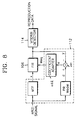
- Figure 8 is a diagram illustrating a channel adaptation model which is applied in calculating coefficients to be stored in the coefficient bank 112 of Figure 3.
- the coefficient adapter of the coefficient bank 112 outputs a coefficient Weq which enables a level error e between an initial non-return zero inversion (NRZI) signal passed through a PR model, for example, PR(a,b,a) or PR(a,b,b,a), not through the MTF channel, to converge to zero.
- the PR model refers to the type of the Viterbi decoder 114 used.
- the constituent blocks of the coefficient bank 112 shown in Figure 8 are implemented by software, not by hardware.
- Such extraction of the coefficient Weq may be performed for limited cases, for example, when the degree of defocusing is 15 ⁇ m, 30 ⁇ m, 45 ⁇ m or 60 ⁇ m, or when a tangential tilt angle is 0.125°, 0.25°, 0.375 ° or 0.5°, and then the obtained coefficients may be stored in the coefficient bank 112.
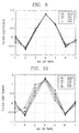
- the tap coefficients of the equalizer (7-tap) 106 which were obtained by applying the method illustrated in Figure 8, are shown versus the number of taps in Figure 9.
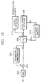
- the tap coefficients of the equalizer (7-tap)106 which were obtained by the method of Figure 8, are shown versus the number of taps in Figure 10.
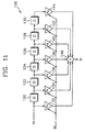
- the structure of the equalizer which is constructed of a 7-tap FIR filter, is shown in Figure 11.
- the 7-tap FIR filter is characterized in that each tap coefficient can be separately and asymmetrically set around the center tap K d .
- x k indicates the input data of the equalizer 106
- y k indicates the output data of the equalizer 106
- W k+1 indicates the coefficients of the equalizer 106 after adaptation.
- Reference numerals 120, 122, 124, 126, 128 and 130 represent delays
- reference numerals 132, 134, 136, 138, 140, 142 and 144 represent multipliers
- reference numeral 146 represents an adder.
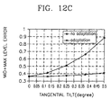
- Figures 12A through 12C comparatively show level errors with respect to variations in tangential tilt angle when the tap coefficients of the equalizer are fixed, and adapted as shown in Figure 10.
- a PR (1,2,1) type Viterbi detector was used.
- the tangential tilt angle is increased up to 0.5°, the variation in level error is much less than when fixed coefficients are used.
- the difference in the amplitudes of level errors when using fixed and adapted coefficients, respectively increases at larger tangential tilt angles.
- Figure 12A shows the variation in the middle level error with respect to tangential tilt angle when the tap coefficients of the equalizer are adapted and fixed.
- Figure 12B shows the variation in the maximum level error with respect to tangential tilt angle when the tap coefficients of the equalizer are adapted and fixed.
- Figure 12C shows the variation in the sum of the middle and maximum level errors with respect to tangential tilt angle when the tap coefficients of the equalizer are adapted and fixed.
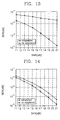
- Figures 13 and 14 show that when a tangential tilt angle of 0.5° or a degree of defocusing of 60 ⁇ m occurs, the bit error rate (BER) of a reproduction signal output from the Viterbi decoder can be reduced more by using adapted coefficients than by using fixed coefficients.
- BER bit error rate
- Figure 13 illustrates the effect of using adapted coefficients on the error rate of the reproduction signal, compared to the case of using fixed coefficients, when a tangential tilt of 0.5° occurs.
- Figure 14 illustrates the effect of using adapted coefficients on the error rate of the reproduction signal, compared to the case of using fixed coefficients, when defocusing of 60 ⁇ m occurs.
- the data reproduction apparatus includes an ADC 200, an asymmetry compensator 202, an adder 204, an equalizer 206 and a Viterbi detector 212.
- the elements are the same as these of Figure 3, and thus a description of their structure won't be repeated here.
- the filter coefficients of the equalizer 206 are obtained by adaptation in the coefficient adapter 210, using formula 1 to minimize the error value e k .
- W k +1 W k +2 ⁇ e k ⁇ x k
- W k+1 indicates a filter coefficient of the equalizer after adaptation
- W k indicates a filter coefficient of the equalizer before adaptation
- ⁇ is a coefficient relating to equalization rate (0.001 for the present embodiment)
- e k indicates a level error
- x k indicates an RF signal after asymmetry correction.
- Figure 16 illustrates still another embodiment of a data reproduction apparatus according to the present invention, further having a defocus/tilt detection function.
- the only difference between the structure of this embodiment and the structure shown in Figure 15 is that the defocus/tilt detector 314 is further included.
- the defocus/tilt detector 314 is further included.
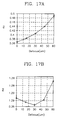
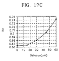
- the operation of the defocus/tilt detector 314 will be described with reference to the tap coefficient variation curves shown in Figures 17A through 17C and Figures 18A through 18C, and Figure 19.
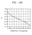
- the filter coefficients of the equalizer 306 vary as shown in Figures 18A through 18C.
- the left and right tap coefficients K c and K e show opposite tendencies around the central tap coefficient K d , i.e., if one of the left and right tap coefficients K c and K e increases, the other tap coefficient decreases.
- Figures 18A through 18C illustrate the variation of the left tap coefficient K c , the center tap coefficient K d , and the right tap coefficient K e , respectively, according to the tangential tilt angle.
- the defocus/tilt detector 314 outputs a tangential tilt signal t_tilt_r or t_tilt_l.
- the signal t_tilt_r indicates that a recording medium is tilted in the moving direction of a pickup
- the signal t_tilt_r indicates that the recording medium is tilted in the opposite direction.
- Figure 19 is a flowchart illustrating the detection of defocusing or tilting by the defocus/tilt detector shown in Figure 16.
- the operation of the defocus/tilt detector begins with reception of a servo abnormal signal (S501).
- S501 servo abnormal signal
- the servo abnormal signal can be detected directly from a servo unit or a pickup unit by a system microcomputer.
- step S502 it is determined whether the filter coefficient K c on the left of the center tap coefficient K d increases. If the left filter coefficient K c increases, it is determined whether the filter coefficient K e on the right of the center tap coefficient K d increases (S503). If both the left and right filter coefficients K c and K e increase, a defocus signal is output (S504). If it is determined in step S503 that the filter coefficient K e does not increase, it is determined whether the filter coefficient K e decreases (S505). If the filter coefficient K c increases and the filter coefficient K e decreases, a tangential tilt signal t_tilt_l or t_tilt_r is output (S506).
- the filter coefficients of the equalizer which is connected in front of the Viterbi decoder, are selected such that the level error to be input to the Viterbi detector is minimized, thereby improving the reproduction performance.
- the level error is detected by adapting the filter coefficients of the equalizer according to the PR type of the Viterbi decoder, so that the level error is minimized with enhanced reproduction characteristics.
- the servo status can be inferred from variations in the filter coefficients of the equalizer. In other words, whether defocusing or tangential tilting occurs, and the direction of the tangential tilting can be detected. Thus, when jittering of data occurs due to defocusing or tilting, the error rate of data can be improved by adjusting the filter coefficients of the equalizer.
Landscapes
- Engineering & Computer Science (AREA)
- Signal Processing (AREA)
- Physics & Mathematics (AREA)
- Probability & Statistics with Applications (AREA)
- Artificial Intelligence (AREA)
- Computer Networks & Wireless Communication (AREA)
- Algebra (AREA)
- Pure & Applied Mathematics (AREA)
- Signal Processing For Digital Recording And Reproducing (AREA)
- Dc Digital Transmission (AREA)
- Cable Transmission Systems, Equalization Of Radio And Reduction Of Echo (AREA)
- Filters That Use Time-Delay Elements (AREA)
Abstract
Description
Claims (31)
- A data reproduction apparatus including a data detector for detecting data based on partial response maximum likelihood (PRML), the apparatus comprising:an equalizer comprising a digital filter (106);a level error detector (108) for extracting a level of the output value of the equalizer based on a reference level set in the data detector, and detecting a level error between the level of the output value and a predetermined reference value;a coefficient bank (112) for storing filter coefficients of the equalizer; anda coefficient selector (110) for selecting the filter coefficients of the equalizer from the coefficient bank such that the level error is minimized.
- The data reproduction apparatus of claim 1, wherein the error detector predetermines at least one reference value corresponding to zero level, positive and negative middle levels, and positive and negative maximum levels, which are classified depending on the partial response (PR) type of the data detector and detects the levels from the output value of the equalizer, and outputs the level error corresponding to differences between the detected levels and corresponding reference values.
- The data reproduction apparatus of claim 1 or 2, wherein the error detector determines whether or not the product of two successive sampling data output from the equalizer is less than 0, determines which one of the sampling data is greater than 0 if the product of the two successive sampling data is less than 0, determines the sampling data greater than 0 as the positive middle level, and the sampling data less than 0 as the negative middle level, and detects level errors corresponding to the differences between the values of the sampling data determined as the positive and negative middle levels, and corresponding reference values.
- The data reproduction apparatus of claim 1,2 or 3, wherein the error detector determines whether or not all three successive sampling data output from the equalizer are greater than a predetermined threshold value, determines the middle sampling data as the positive maximum level if all of the three successive sampling data are greater than the predetermined threshold value, and determines the middle sampling data as the negative maximum level if all of the three successive sampling data are less than the predetermined threshold value, and detects level errors corresponding to the differences between the values of the sampling data determined as the positive and negative maximum levels, and corresponding reference values.
- The data reproduction apparatus of any preceding claim, wherein the error detector determines whether or not the product of two successive sampling data output from the equalizer is less than or equal to 0, and determines the sampling data whose absolute value is less than the absolute value of the other sampling data as the zero level, and detects the difference between the value of the sampling data determined as the zero level and a corresponding reference value.
- The data reproduction apparatus of any preceding claim, wherein the error detector determines whether the product of two successive sampling data output from the equalizer is less than or equal to 0, compares the absolute values of the two successive data if the product of two successive sampling data output from the equalizer is less than or equal to 0, determines the latter of the two successive sampling data, and the sampling data preceding the two successive sampling data to be the positive and negative middle levels, respectively, if the absolute value of the latter of the two successive sampling data is greater than that of the other sampling data, determines the sampling data preceding the two successive sampling data, and the sampling data following the two successive sampling data to be the positive and negative middle levels, respectively, if the absolute value of the former of the two successive sampling data is and greater than or equal to the other sampling data, and detects level errors corresponding to the differences between the values of the sampling data determined as the negative and positive middle levels, arid corresponding reference values.
- The data reproduction apparatus of any preceding claim, wherein the coefficient bank (112) stores the filter coefficients of the equalizer, which are adapted according to the servo status and the degree of defocusing and tangential tilting.
- The data reproduction apparatus of any preceding claim, wherein the coefficient selector (110) selects coefficients stored in the coefficient bank according to a coefficient change request signal input from the outside to replace the filter coefficients of the equalizer with the selected coefficients, checks the level error output from the level error detector, and determines the coefficients which minimize the level error to be the final filter coefficients of the equalizer.
- A data reproduction apparatus including a data detector for detecting data based on partial response maximum likelihood (PRML), the apparatus comprising:an equalizer (106) comprising a digital filter;a level error detector (1121) for extracting a level of the output value of the equalizer (106) based on a reference level set in the data detector, and detecting a level error between the level of the output value and a predetermined reference value; anda coefficient adapter (1122) for adapting filter coefficients of the equalizer such that a difference between the level error and a target level error is minimized.
- The data reproduction apparatus of claim 9, wherein the error detector predetermines at least one reference value corresponding to zero level, positive and negative middle levels, and positive and negative maximum levels, which are classified depending on the partial response (PR) type of the data detector and detects the levels from the output value of the equalizer, and outputs the level error corresponding to differences between the detected levels and corresponding reference values.
- The data reproduction apparatus of claim 9 or 10, wherein the error detector determines whether or not the product of two successive sampling data output from the equalizer is less than 0, determines which one of the sampling data is greater than 0 if the product of the two successive sampling data is less than 0, determines the sampling data greater than 0 as the positive middle level, and the sampling data less than 0 as the negative middle level, and detects level errors corresponding to the differences between the values of the sampling data determined as the positive and negative middle levels, and corresponding reference values.
- The data reproduction apparatus of claim 9, 10 or 11, wherein the error detector determines whether or not all three successive sampling data output from the equalizer are greater than a predetermined threshold value, determines the middle sampling data as the positive maximum level if all of the three successive sampling data are greater than the predetermined threshold value, and determines the middle sampling data as the negative maximum level if all of the three successive sampling data are less than the predetermined threshold value, and detects level errors corresponding to the differences between the values of the sampling data determined as the positive and negative maximum levels, and corresponding reference values.
- The data reproduction apparatus of claim 9, 10, 11 or 12, wherein the error detector determines whether or not the product of two successive sampling data output from the equalizer is less than or equal to 0, and determines the sampling data whose absolute value is less than the absolute value of the other sampling data as the zero level, and detects the difference between the value of the sampling data determined as the zero level and a corresponding reference value.
- The data reproduction apparatus of claim 9,10, 11, 12 or 13, wherein the error detector determines whether the product of two successive sampling data output from the equalizer is less than or equal to 0, compares the absolute values of the two successive data if the product of two successive sampling data output from the equalizer is less than or equal to 0, determines the latter of the two successive sampling data, and the sampling data preceding the two successive sampling data to be the positive and negative middle levels, respectively, if the absolute value of the latter of the two successive sampling data is greater than that of the other sampling data, determines the sampling data preceding the two successive sampling data, and the sampling data following the two successive sampling data to be the positive and negative middle levels, respectively, if the absolute value of the former of the two successive sampling data is and greater than or equal to the other sampling data, and detects level errors corresponding to the differences between the values of the sampling data determined as the negative and positive middle levels, and corresponding reference values.
- The data reproduction apparatus of any of claims 9 to 14, further comprising a defocus/tilt detector for detecting the servo status by monitoring variations of the adaptive filter coefficients of the equalizer.
- The data reproduction apparatus of claim 15, wherein the defocus/tilt detector determines a state where both side tap coefficients around the central tap coefficient of the equalizer increase to be a state of defocus, and outputs a defocus signal.
- The data reproduction apparatus of claim 15 or 16, wherein the defocus/tilt detector determines a state where one side tap coefficient with respect to the central tap coefficient of the equalizer increases while the opposite side tap coefficient decreases to be a state of tangential tilting, and outputs a tangential tilt signal.
- The data reproduction apparatus of claim 17, wherein the defocus/tilt detector determines the direction of the tangential tilting according to which side tap coefficient increases or decreases with respect to the central tap coefficient.
- A data reproduction method capable of improving the performance of a data detector for detecting data based on partial response maximum likelihood (PRML) by adjusting filter coefficients of an equalizer comprising a digital filter, connected before the data detector, the method comprising the steps of:(a) extracting a level of the output data of the equalizer based on a reference level set in the data detector, and detecting a level error between the level of the output data and a predetermined reference value; and(b) adjusting the filter coefficients of the equalizer such that the level error is minimized.
- The data reproduction method of claim 19, wherein in step (a), at least one reference value corresponding to zero level, positive and negative middle levels, or positive and negative maximum levels, which are classified depending on the partial response (PR) type of the data detector is predetermined, a level of the output value of the equalizer is detected based on the classified levels, and the level error is detected corresponding to differences between the detected levels and corresponding reference values.
- The data reproduction method of claim 19, wherein step (a) comprises:(a1) determining whether or not the product of two successive sampling data output from the equalizer is less than 0, determining which one of the sampling data is greater than 0 if the product of the two successive sampling data is less than 0, determining the sampling data greater than 0 as the positive middle level, and the sampling data less than 0 as the negative middle level; and(a2) detecting level errors corresponding to the differences between the values of the sampling data determined as the positive and negative middle levels, and corresponding reference values.
- The data reproduction method of claim 19, wherein step (a) comprises:(a1) determining whether or not all three successive sampling data output from the equalizer are greater than a predetermined threshold value, determining the middle sampling data as the positive maximum level if all of the three successive sampling data are greater than the predetermined threshold value, and the middle sampling data as the negative maximum level if all of the three successive sampling data are less than the predetermined threshold value; and(b) detecting level errors corresponding to the differences between the values of the sampling data determined as the positive and negative maximum levels, and corresponding reference values.
- The data reproduction method of claim 20, wherein step (a) comprises:(a1) determining whether or not the product of two successive sampling data output from the equalizer is less than or equal to 0, and determining the sampling data whose absolute value is less than the absolute value of the other sampling data as the zero level; and(a2) detecting the difference between the value of the sampling data determined as the zero level and a corresponding reference value.
- The data reproduction method of claim 20, wherein step (a) comprises:(a1) determining whether or not the product of two successive sampling data output from the equalizer is less than or equal to 0, and comparing the absolute values of the two successive data;(a2) determining the latter of the two successive sampling data, and the sampling data preceding the two successive sampling data to be the positive and negative middle levels, respectively, if the absolute value of the latter of the two successive sampling data is greater than that of the other sampling data;(a3) detecting level errors corresponding to the differences between the values of the sampling data determined as the negative and positive middle levels in step (a2), and corresponding reference values;(a4) determining the sampling data preceding the two sampling data, and the latter of the two successive sampling data to be the positive and negative middle levels, respectively, if the absolute value of the former of the two successive sampling data is greater than or equal to the other sampling data; and(a5) detecting level errors corresponding to the differences between the values of the sampling data determined as the negative and positive middle levels in step (a4), and corresponding reference values.
- The data reproduction method of claim 19, wherein in step (b) the filter coefficients of the equalizer are adapted according to the servo status and the degree of defocusing and tangential tilting.
- The data reproduction method of claim 19, wherein in step (b) the filter coefficients of the equalizer are changed according to a coefficient change request signal input from the outside, and the level error is continuously checked to determine the coefficients which minimize the level error as the final filter coefficients of the equalizer.
- The data reproduction method of claim 19, wherein in step (b) the filter coefficients of the equalizer are adapted such that a difference between the level error and a target level error is minimized.
- The data reproduction method of claim 27, further comprising (c) monitoring the adaptive filter coefficients of the equalizer and determining the servo status according to the variations of the adaptive filter coefficients.
- The data reproduction method of claim 28, wherein in step (c) when both side tap coefficients around the central tap coefficient of the equalizer increase, the state is determined to be a state of defocus.
- The data reproduction method of claim 28, wherein in step (c) when one side tap coefficient with respect to the central tap coefficient increases while the opposite side tap coefficient decreases, the state is determined to be a state of tangential tilting.
- The data reproduction method of claim 30, wherein in step (c) the direction of the tangential tilting is detecting according to which side tap coefficient increases or decreases.
Applications Claiming Priority (2)
| Application Number | Priority Date | Filing Date | Title |
|---|---|---|---|
| KR9948585 | 1999-11-04 | ||
| KR1019990048585A KR100580166B1 (en) | 1999-11-04 | 1999-11-04 | Apparatus and method for improving playback performance by adjusting filter coefficients of equalizer |
Publications (2)
| Publication Number | Publication Date |
|---|---|
| EP1098313A2 true EP1098313A2 (en) | 2001-05-09 |
| EP1098313A3 EP1098313A3 (en) | 2006-06-07 |
Family
ID=19618497
Family Applications (1)
| Application Number | Title | Priority Date | Filing Date |
|---|---|---|---|
| EP00309356A Withdrawn EP1098313A3 (en) | 1999-11-04 | 2000-10-24 | Data reproduction apparatus and method with improved performance by adjusting filter coefficients of equalizer |
Country Status (6)
| Country | Link |
|---|---|
| US (2) | US6747936B1 (en) |
| EP (1) | EP1098313A3 (en) |
| JP (1) | JP2001189053A (en) |
| KR (1) | KR100580166B1 (en) |
| CN (1) | CN1136573C (en) |
| TW (1) | TW564402B (en) |
Cited By (6)
| Publication number | Priority date | Publication date | Assignee | Title |
|---|---|---|---|---|
| WO2004105026A1 (en) * | 2003-05-20 | 2004-12-02 | Koninklijke Philips Electronics N.V. | Device and method of retrieving a data signal stored on an optical data carrier |
| WO2004105027A1 (en) * | 2003-05-20 | 2004-12-02 | Koninklijke Philips Electronics N.V. | System and method of estimating the tangential tilt of an optical data carrier.. |
| WO2004105029A1 (en) * | 2003-05-21 | 2004-12-02 | Koninklijke Philips Electronics N.V. | Device and method of compensating the distortions in optical data carrier scanning |
| WO2004105028A1 (en) * | 2003-05-20 | 2004-12-02 | Koninklijke Philips Electronics N.V. | System and method of compensating the tangential tilt in an optical data carrier signal |
| WO2005027120A1 (en) * | 2003-09-16 | 2005-03-24 | Samsung Electronics Co., Ltd. | Apparatus and method for measuring signal quality |
| US7184476B2 (en) | 2001-12-11 | 2007-02-27 | Samsung Electronics Co., Ltd. | Adaptive equalizer for controlling operation thereof by using sign and absolute value of output signal thereof |
Families Citing this family (27)
| Publication number | Priority date | Publication date | Assignee | Title |
|---|---|---|---|---|
| HK1042966B (en) * | 1999-05-11 | 2005-04-29 | Niigata Seimitsu Co., Ltd. | Interpolation circuit |
| JP3928332B2 (en) * | 2000-05-11 | 2007-06-13 | 株式会社日立製作所 | Adaptive equalization circuit |
| JP3529767B2 (en) * | 2002-03-08 | 2004-05-24 | 株式会社東芝 | Information reproducing apparatus and information reproducing method |
| JP3580292B2 (en) * | 2002-03-20 | 2004-10-20 | 船井電機株式会社 | Disc playback device |
| KR100878524B1 (en) | 2002-05-21 | 2009-01-13 | 삼성전자주식회사 | Filter tap coefficient update device and update method of equalizer |
| JP4102738B2 (en) * | 2002-12-17 | 2008-06-18 | 日本電気株式会社 | Optical disk signal quality evaluation method, quality evaluation apparatus, and optical disk apparatus |
| JP3813931B2 (en) * | 2003-01-31 | 2006-08-23 | 株式会社東芝 | Information reproducing apparatus and information reproducing method |
| US7154424B2 (en) * | 2003-02-28 | 2006-12-26 | Matsushita Electric Industrial Co., Ltd. | Digital equalization apparatus |
| JP4151600B2 (en) * | 2003-10-30 | 2008-09-17 | 日本電気株式会社 | Information reproducing method and information reproducing apparatus |
| CN1875419A (en) * | 2003-11-11 | 2006-12-06 | 松下电器产业株式会社 | Filter coefficient adjusting circuit |
| US7489750B1 (en) * | 2004-01-15 | 2009-02-10 | Marvell International Ltd. | DC-control for post processor |
| KR100528878B1 (en) * | 2004-02-16 | 2005-11-16 | 삼성전자주식회사 | High speed mixed analog/digital PRML data detecting and clock recovery device fot data storage |
| JP4456928B2 (en) * | 2004-05-14 | 2010-04-28 | 株式会社日立製作所 | Optical disk device |
| JP4544915B2 (en) * | 2004-06-03 | 2010-09-15 | ルネサスエレクトロニクス株式会社 | Receiver and analog / digital converter |
| US7511910B1 (en) | 2004-10-27 | 2009-03-31 | Marvell International Ltd. | Asymmetry correction in read signal |
| US7298570B1 (en) | 2004-10-27 | 2007-11-20 | Marvell International Ltd. | Asymmetry correction in read signal |
| US7430084B2 (en) * | 2004-12-03 | 2008-09-30 | International Business Machines Corporation | Magnetic tape read channel signal values developed employing intermediate bits of the path memory of a PRML viterbi detector |
| KR100614241B1 (en) * | 2005-02-07 | 2006-08-21 | 삼성전자주식회사 | Method and apparatus for setting initial value of adaptive equalizer |
| TWI353725B (en) * | 2006-10-16 | 2011-12-01 | Mstar Semiconductor Inc | Equalizer using infinitive impulse response filter |
| US8619532B1 (en) * | 2007-04-17 | 2013-12-31 | Marvell International Ltd. | Asynchronous asymmetry compensation |
| US8477581B1 (en) * | 2007-04-17 | 2013-07-02 | Marvell International Ltd. | Asymmetry compensation system |
| KR20090051622A (en) * | 2007-11-19 | 2009-05-22 | 삼성전자주식회사 | Data playback device and method |
| US7952502B2 (en) * | 2008-08-29 | 2011-05-31 | Broadcom Corporation | Imbalance and distortion cancellation for composite analog to digital converter (ADC) |
| JP4764939B2 (en) * | 2009-04-14 | 2011-09-07 | 株式会社日立製作所 | Recording condition adjusting method and optical disc apparatus |
| US20110090773A1 (en) * | 2009-10-16 | 2011-04-21 | Chih-Ching Yu | Apparatus for generating viterbi-processed data using an input signal obtained from reading an optical disc |
| US20110090779A1 (en) * | 2009-10-16 | 2011-04-21 | Mediatek Inc. | Apparatus for generating viterbi-processed data |
| CN104078050A (en) * | 2013-03-26 | 2014-10-01 | 杜比实验室特许公司 | Device and method for audio classification and audio processing |
Family Cites Families (24)
| Publication number | Priority date | Publication date | Assignee | Title |
|---|---|---|---|---|
| JP3250678B2 (en) | 1992-08-25 | 2002-01-28 | ソニー株式会社 | Coefficient processing method, coefficient processing circuit, and video tape recorder |
| JPH06124542A (en) | 1992-10-09 | 1994-05-06 | Sony Corp | Signal equalization method, signal equalization circuit, and video tape recorder |
| JP3560351B2 (en) | 1993-08-05 | 2004-09-02 | 株式会社日立製作所 | Optical information recording / reproducing method |
| JP3059868B2 (en) | 1993-07-29 | 2000-07-04 | 三洋電機株式会社 | Optical information reproducing device |
| KR960012019B1 (en) * | 1993-11-18 | 1996-09-09 | 엘지전자 주식회사 | HDTV's Channel Equalizer |
| JP3326946B2 (en) | 1994-01-10 | 2002-09-24 | ソニー株式会社 | Optical disk reproducing apparatus and optical disk reproducing method |
| JPH07235150A (en) | 1994-02-24 | 1995-09-05 | Sony Corp | Digital signal recording / reproducing method and digital signal recording / reproducing apparatus |
| JP3319161B2 (en) | 1994-07-19 | 2002-08-26 | ソニー株式会社 | Skew control device |
| JP2888161B2 (en) | 1995-03-15 | 1999-05-10 | 日本電気株式会社 | Information playback device |
| JP3648308B2 (en) * | 1995-11-30 | 2005-05-18 | 株式会社日立グローバルストレージテクノロジーズ | Equalizer and magnetic recording signal reproducing apparatus |
| JPH09231573A (en) | 1996-02-27 | 1997-09-05 | Sony Corp | Optical information reproducing device |
| JPH09259543A (en) | 1996-03-25 | 1997-10-03 | Hitachi Ltd | Magnetic recording / reproducing device |
| US6819514B1 (en) | 1996-04-30 | 2004-11-16 | Cirrus Logic, Inc. | Adaptive equalization and interpolated timing recovery in a sampled amplitude read channel for magnetic recording |
| JP3585317B2 (en) | 1996-05-27 | 2004-11-04 | パイオニア株式会社 | Recorded information playback device |
| US6437932B1 (en) | 1996-05-16 | 2002-08-20 | Lsi Logic Corporation | Decision based time-varying equalizers |
| JPH1091964A (en) | 1996-09-13 | 1998-04-10 | Pioneer Electron Corp | Adaptive equalizer of recorded information reproducing device |
| US6198711B1 (en) * | 1996-12-24 | 2001-03-06 | Sony Corporation | Equalizer for optical reproducing apparatus, using partial response method |
| US5999349A (en) * | 1996-12-30 | 1999-12-07 | Daewoo Electronics Co., Ltd. | Waveform equalization apparatus |
| JPH10283729A (en) | 1997-04-08 | 1998-10-23 | Ricoh Co Ltd | Waveform equalizer and optical disk recording / reproducing device |
| KR100238322B1 (en) * | 1997-11-06 | 2000-01-15 | 윤종용 | Viterbi detection method and apparatus |
| KR100257730B1 (en) * | 1997-11-29 | 2000-06-01 | 전주범 | Adaptive equalizer for dvcr |
| KR100257728B1 (en) * | 1997-11-29 | 2000-06-01 | 전주범 | Equalizer for dvcr |
| JPH11273256A (en) | 1998-03-26 | 1999-10-08 | Matsushita Electric Ind Co Ltd | Automatic equalization circuit |
| JP3638093B2 (en) * | 1998-12-04 | 2005-04-13 | 日本ビクター株式会社 | Optical disc decoding device |
-
1999
- 1999-11-04 KR KR1019990048585A patent/KR100580166B1/en not_active Expired - Fee Related
-
2000
- 2000-10-24 EP EP00309356A patent/EP1098313A3/en not_active Withdrawn
- 2000-10-27 JP JP2000329183A patent/JP2001189053A/en active Pending
- 2000-11-02 CN CNB00133882XA patent/CN1136573C/en not_active Expired - Fee Related
- 2000-11-03 US US09/704,549 patent/US6747936B1/en not_active Expired - Fee Related
-
2001
- 2001-01-20 TW TW089122758A patent/TW564402B/en not_active IP Right Cessation
-
2004
- 2004-04-30 US US10/835,003 patent/US7061848B2/en not_active Expired - Fee Related
Cited By (8)
| Publication number | Priority date | Publication date | Assignee | Title |
|---|---|---|---|---|
| US7184476B2 (en) | 2001-12-11 | 2007-02-27 | Samsung Electronics Co., Ltd. | Adaptive equalizer for controlling operation thereof by using sign and absolute value of output signal thereof |
| WO2004105026A1 (en) * | 2003-05-20 | 2004-12-02 | Koninklijke Philips Electronics N.V. | Device and method of retrieving a data signal stored on an optical data carrier |
| WO2004105027A1 (en) * | 2003-05-20 | 2004-12-02 | Koninklijke Philips Electronics N.V. | System and method of estimating the tangential tilt of an optical data carrier.. |
| WO2004105028A1 (en) * | 2003-05-20 | 2004-12-02 | Koninklijke Philips Electronics N.V. | System and method of compensating the tangential tilt in an optical data carrier signal |
| WO2004105029A1 (en) * | 2003-05-21 | 2004-12-02 | Koninklijke Philips Electronics N.V. | Device and method of compensating the distortions in optical data carrier scanning |
| WO2005027120A1 (en) * | 2003-09-16 | 2005-03-24 | Samsung Electronics Co., Ltd. | Apparatus and method for measuring signal quality |
| US7801005B2 (en) | 2003-09-16 | 2010-09-21 | Samsung Electronics Co., Ltd. | Apparatus and method for measuring signal quality |
| US7952974B2 (en) | 2003-09-16 | 2011-05-31 | Samung Electronics Co., Ltd. | Apparatus and method for measuring signal quality |
Also Published As
| Publication number | Publication date |
|---|---|
| JP2001189053A (en) | 2001-07-10 |
| CN1136573C (en) | 2004-01-28 |
| US20040202081A1 (en) | 2004-10-14 |
| US6747936B1 (en) | 2004-06-08 |
| US7061848B2 (en) | 2006-06-13 |
| KR20010045325A (en) | 2001-06-05 |
| TW564402B (en) | 2003-12-01 |
| EP1098313A3 (en) | 2006-06-07 |
| KR100580166B1 (en) | 2006-05-15 |
| CN1295330A (en) | 2001-05-16 |
Similar Documents
| Publication | Publication Date | Title |
|---|---|---|
| EP1098313A2 (en) | Data reproduction apparatus and method with improved performance by adjusting filter coefficients of equalizer | |
| US6977970B2 (en) | Data reproducing apparatus and method for improving detection performance by adjusting decision levels used in data detector | |
| US6934233B2 (en) | Waveform equalizer for a reproduction signal obtained by reproducing marks and non-marks recorded on a recording medium | |
| KR100527524B1 (en) | Optical disc reproduction apparatus | |
| US20070140088A1 (en) | Evaluating apparatus and evaluating method | |
| US7274645B2 (en) | Reproduction signal processing apparatus and optical disc player including the same | |
| US5870372A (en) | Adaptive equalizer of recorded information reproducing apparatus | |
| EP1528559A1 (en) | Information playback method and apparatus | |
| MX2010007257A (en) | Read-back signal evaluation method, read-back signal evaluation device, and optical disc device provided with same. | |
| JP2002008315A (en) | Optical disk drive | |
| KR100636126B1 (en) | Selective Disturbance Compensation Device and 3T Correction Method During Optical Recording Media Playback | |
| EP1443512A1 (en) | Electronic circuit for decoding a read signal from an optical storage medium | |
| US20050053174A1 (en) | Device and method for data reproduction | |
| US20090129229A1 (en) | Method and apparatus for reproducing data | |
| US20090219793A1 (en) | Method of setting write strategy parameters, and recording and reproducing apparatus for performing the method | |
| US7243297B2 (en) | Method for bit recovery in an asymmetric data channel | |
| EP1441344A1 (en) | Electronic circuit for decoding a read signal from an optical storage medium | |
| JP3083202B2 (en) | Information playback device | |
| US20050058191A1 (en) | Method and apparatus for detecting signal quality and recording medium storing program therefor | |
| KR100708069B1 (en) | Data reproducing method and apparatus for compensating asymmetry to increase data detection performance | |
| JP2005056537A (en) | Optical disk device | |
| JPH07262712A (en) | PRML reproduction circuit |
Legal Events
| Date | Code | Title | Description |
|---|---|---|---|
| PUAI | Public reference made under article 153(3) epc to a published international application that has entered the european phase |
Free format text: ORIGINAL CODE: 0009012 |
|
| 17P | Request for examination filed |
Effective date: 20001103 |
|
| AK | Designated contracting states |
Kind code of ref document: A2 Designated state(s): AT BE CH CY DE DK ES FI FR GB GR IE IT LI LU MC NL PT SE |
|
| AX | Request for extension of the european patent |
Free format text: AL;LT;LV;MK;RO;SI |
|
| PUAL | Search report despatched |
Free format text: ORIGINAL CODE: 0009013 |
|
| AK | Designated contracting states |
Kind code of ref document: A3 Designated state(s): AT BE CH CY DE DK ES FI FR GB GR IE IT LI LU MC NL PT SE |
|
| AX | Request for extension of the european patent |
Extension state: AL LT LV MK RO SI |
|
| AKX | Designation fees paid |
Designated state(s): DE FR GB NL |
|
| 17Q | First examination report despatched |
Effective date: 20070907 |
|
| STAA | Information on the status of an ep patent application or granted ep patent |
Free format text: STATUS: THE APPLICATION IS DEEMED TO BE WITHDRAWN |
|
| 18D | Application deemed to be withdrawn |
Effective date: 20080118 |