EP1097842A2 - Leuchte und Verfahren zum Steuern einer Leuchte für Fahrzeuginnenräume - Google Patents
Leuchte und Verfahren zum Steuern einer Leuchte für Fahrzeuginnenräume Download PDFInfo
- Publication number
- EP1097842A2 EP1097842A2 EP00123837A EP00123837A EP1097842A2 EP 1097842 A2 EP1097842 A2 EP 1097842A2 EP 00123837 A EP00123837 A EP 00123837A EP 00123837 A EP00123837 A EP 00123837A EP 1097842 A2 EP1097842 A2 EP 1097842A2
- Authority
- EP
- European Patent Office
- Prior art keywords
- light
- signal
- transmitter
- receiver
- light source
- Prior art date
- Legal status (The legal status is an assumption and is not a legal conclusion. Google has not performed a legal analysis and makes no representation as to the accuracy of the status listed.)
- Granted
Links
- 230000005540 biological transmission Effects 0.000 claims abstract description 40
- 230000003287 optical effect Effects 0.000 claims abstract description 24
- 238000000034 method Methods 0.000 claims abstract description 19
- 230000008878 coupling Effects 0.000 claims abstract description 16
- 238000010168 coupling process Methods 0.000 claims abstract description 16
- 238000005859 coupling reaction Methods 0.000 claims abstract description 16
- 230000004888 barrier function Effects 0.000 claims abstract description 11
- 230000004913 activation Effects 0.000 claims description 10
- 230000005855 radiation Effects 0.000 claims description 10
- 239000013307 optical fiber Substances 0.000 claims description 5
- 238000001514 detection method Methods 0.000 claims description 3
- 239000000835 fiber Substances 0.000 claims description 3
- 238000013459 approach Methods 0.000 claims description 2
- 238000012790 confirmation Methods 0.000 claims 1
- 238000011161 development Methods 0.000 description 5
- 238000005265 energy consumption Methods 0.000 description 3
- 230000006870 function Effects 0.000 description 3
- 238000010586 diagram Methods 0.000 description 2
- 238000011144 upstream manufacturing Methods 0.000 description 2
- 230000008901 benefit Effects 0.000 description 1
- 238000013461 design Methods 0.000 description 1
- 230000009977 dual effect Effects 0.000 description 1
- 239000013305 flexible fiber Substances 0.000 description 1
- 238000009434 installation Methods 0.000 description 1
- 238000012806 monitoring device Methods 0.000 description 1
- 229920003229 poly(methyl methacrylate) Polymers 0.000 description 1
- 239000004417 polycarbonate Substances 0.000 description 1
- 229920000515 polycarbonate Polymers 0.000 description 1
- 239000004926 polymethyl methacrylate Substances 0.000 description 1
- 230000004044 response Effects 0.000 description 1
- 230000035945 sensitivity Effects 0.000 description 1
- 238000012360 testing method Methods 0.000 description 1
Images


Classifications
-
- G—PHYSICS
- G02—OPTICS
- G02B—OPTICAL ELEMENTS, SYSTEMS OR APPARATUS
- G02B6/00—Light guides; Structural details of arrangements comprising light guides and other optical elements, e.g. couplings
- G02B6/0001—Light guides; Structural details of arrangements comprising light guides and other optical elements, e.g. couplings specially adapted for lighting devices or systems
- G02B6/0005—Light guides; Structural details of arrangements comprising light guides and other optical elements, e.g. couplings specially adapted for lighting devices or systems the light guides being of the fibre type
- G02B6/0006—Coupling light into the fibre
-
- B—PERFORMING OPERATIONS; TRANSPORTING
- B60—VEHICLES IN GENERAL
- B60Q—ARRANGEMENT OF SIGNALLING OR LIGHTING DEVICES, THE MOUNTING OR SUPPORTING THEREOF OR CIRCUITS THEREFOR, FOR VEHICLES IN GENERAL
- B60Q3/00—Arrangement of lighting devices for vehicle interiors; Lighting devices specially adapted for vehicle interiors
- B60Q3/80—Circuits; Control arrangements
- B60Q3/82—Switches specially adapted for vehicle interior lighting, e.g. switching by tilting the lens
Definitions
- the invention relates to a lamp for vehicle interiors with a light source, a Light exit and an optical sensor that switches the light source.
- a lamp which is a light source has, which is surrounded by a reflector that focuses the light of the light source and couples it into an optical fiber.
- an optical one Sensor In front of the light guide is an optical one Sensor, the daylight falling on it from an additionally arranged daylight light guide detected and the light source via a ballast depending on switches the daylight on or off or dims it.
- the disadvantage here is that the light source or the lamp only as a function of Daylight can be switched. An unwanted switching on in the dark can only be prevented by an additional switch.
- the object of the present invention is therefore to improve the known lights in such a way that they can be easily switched by a user even in the dark and are easy and inexpensive to assemble. On a special electrical It should be possible to dispense with switches near the light outlet.
- the optical sensor as Receiver of a reflection light barrier is formed, the optical transmitter Emits light via the light exit, which reflects when approaching the light exit, and can be directed at least partially to the receiver via the light outlet.
- the luminaire By designing the optical sensor as a receiver of a reflection light barrier the luminaire can be used without contact by approaching the light outlet switched by hand or an object. Under switching here Functions switching on / off and dimming can be understood.
- a light guide is arranged on its side facing the light source End has a light entry surface into which the light of the light source is coupled becomes.
- the light source is surrounded by a reflector that the light of the The light source bundles and couples it into the light entry surface.
- the transmitter and receiver can be adjacent to the light source and relatively simple be supplied with electrical energy. On the arrangement of a separate one electrical switch near the light outlet and on an electrical feed an electrical switch can be dispensed with entirely. So it is it is not necessary to lay an electrical line parallel to the light guide. The Installation and product costs are significantly reduced.
- the optical Transmitter designed as an infrared light emitting diode.
- the recipient is one Infrared photodiode or designed as an infrared phototransistor.
- transmitters and Receiver positioned on the reflector of the light source so that on the one hand as possible small reflector area is required and on the other hand transmitter and receiver the light entry surface are focused.
- the arrangement of the transmitter and receiver on the reflector makes it relatively compact Structure of the lamp achieved.
- the invention is between the light source and light entry surface arranged a partially transparent mirror over which The transmitter and receiver are focused on the light entry surface.
- the transmitter and receiver can be used close together at right angles to the optical axis of the light source be arranged with reflector.
- the connection to the necessary electronic Circuit is particularly easy to implement.
- transmitters and Receiver arranged on the back of the reflector facing away from the light source.
- the reflector is transparent to infrared radiation, so that infrared radiation
- the transmitter and receiver are focused on the light entry surface.
- the reflector projects essentially only the visible part of the light Light source through the light entry surface in the light guide, so that a passage for infrared radiation is possible.
- the transmitter and receiver can advantageously be positioned in this way be that a largely unhindered passage of infrared rays through the reflector is possible. If necessary, for optimal focusing the rays other optical elements, such as. B. Fresnel lenses, behind the reflector to be ordered.
- transmitters and Receiver connected to the light outlet via light guide.
- the light guides are there designed as a fiber optic light guide.
- the light source is coupled to a control unit, which is preferably on a back of the Light source is arranged. This ensures that when the Do not light the control unit through the cover plate from the surroundings is visible from.
- the lamp has a compact design Structure on, where they are arranged to save space in an opening of the vehicle can.
- both the transmitter and the receiver are arranged on a circuit board carrying the control unit.
- the transmitter and receiver can be equipped with an additional light guide in the direction of light propagation Decoupling point at the front, emitting the transmission signal or the coupling point receiving the receiving signal.
- the additional light guides become the light emitted by the light source leading light guide, which acts as a transmission channel for the transmission signal or the received signal is used.
- the reflector of the lamp has an opening in which the additional light guide in the direction of the transmitter or receiver runs, so that the transmitter or the receiver saves space in the area of Edge of the reflector can be arranged on the back of the same.
- the transmitter or the receiver is arranged in a region of the reflector near the edge is the beam path of the light emitted by the light source only slightly disturbed.
- the light source is a light-emitting diode in which a modulated transmission signal generated by the control unit is memorable.
- the light source has a dual function. For one, it serves They are used to generate light beams that are used to illuminate the vehicle interior serve. On the other hand, it serves as a transmitter for generating a transmission signal by means of the presence of a body moved near the lamp can be checked.
- Another object of the present invention is to provide a method for controlling a Specify luminaire for vehicle interiors so that a safe and reliable Detection of a near the luminaire or a specified coupling point same moving body is recognized, the comfort when operating the lamp is raised.
- This object is thereby in connection with the preamble of claim 18 solved that that generates a pattern signal from a transmitter of the optical sensor and a decoupling point of the luminaire is supplied via a coupling point the lamp receives a signal to a receiver of the optical sensor is routed that the received signal with the pattern signal generated by the transmitter is compared so that the received signal as one at a near the Decoupling body held reflected reflection signal can be detected can, and that if there is a match of the received signal with the Pattern signal the control signal is generated to control the light source.
- the method according to the invention according to claim 18 enables reliable detection a body moved near the lamp, especially a hand.
- the transmission signal as a pattern signal, preferably as a modulated transmission signal is formed by comparing it with a detected one Received signal safely the reflection signal from an undesirable switching operation a distinction is made between extraneous light.
- the transmission signal radiated as a pulse-modulated transmission signal from the transmitter so that Transmit signal can be generated using a simple pulse modulation circuit can.
- Another object of the present invention is to provide a method for controlling a Specify light for vehicle interiors, so that the safe and reliable Activation of the lamp by approaching a body to the same allows is, the control of the lamp with a relatively low energy consumption he follows.
- control unit is in an energy-saving sleep state and only then changes to an alarm state emitting a pattern signal, when a received signal is detected in a receiver that in the Wake-up state of the control unit the pattern signal is emitted by a transmitter and then the received signal detected by the receiver for agreement is checked with the transmitted pattern signal to detect an in near a decoupled body and that in the activated state the control unit a control signal is generated to control the light source.
- control unit of the lamp is basically in a sleep state in which no transmission signals are sent. It advantageously flows in this sleep state no quiescent current in the transmitter, so that the energy consumption is significantly reduced can be. Only the receiver is in a receive state, so that receive signals can be detected. In the event that a received signal is detected is, the control unit is placed in an alarm state in which a transmission signal generated and emitted by the transmitter. Now in connection with checks the presence of a reflection signal for a detected reception signal are, whereby in the positive case the control unit is placed in the activation state becomes. In the activation state, the control unit sends a control signal to the Light source emitted, which causes the same to turn on.
- the control unit will put back into sleep mode by virtually turning off the transmitter.
- the basic idea of the method according to the invention is to basically transmit the transmitter to keep a switched off state and this only when there is a received signal in a wake-up state causing the generation of a transmission signal to move. As a result, lights can be switched contact-free to save energy become.
- the control unit also depending on the actuation of a functional element assigned to the lamp be brought into an alarm state.
- the Both the sender and the receiver are located during the procedure Control unit sleep state in a switched-off state.
- the functional element After actuation of the functional element is only the receiver in an operating state transferred.
- the transmitter is only woken up when the receiver has detected a received signal.
- the functional element be designed as a sun visor, which in a folded-up position Control unit in the sleep state and in the folded down position the receiver put in the operating state.
- a lamp 1 for vehicle interiors essentially consists of a light source 2, a reflector 3, a light guide 4 and a light exit element 5.
- the light source 2 is arranged in a first focal point of the reflector 3 the light from the light source is arranged on a first end 6 of the light guide 4 Light entry surface 7 focused.
- the light guide 4 has the first End 6 facing away from second end 8 on light exit element 5. Not one facing the interior of the vehicle, the light exit element 5 has a light exit 9.
- the reflector 3 has a first lateral opening 10 in which a transmitter 11 is arranged is.
- the transmitter 11 is designed as an infrared light-emitting diode (IR-LED) 12, the free end 13 in a reflector space spanned by the reflector 3 14 protrudes.
- the transmitter 11 or the infrared light emitting diode 12 is in the reflector 3 arranged that the infrared light emitted by it on the light entry surface 7 is focused and coupled into the light guide 4.
- a second Lateral opening 15 of the reflector 3 is an optical sensor or receiver 16 arranged.
- the receiver 16 is designed as an infrared photodiode 17, which with its free end 18 via the second lateral opening 15 into the reflector space 14 protrudes that it is focused on the light entry surface 7 of the light guide 4 and Infrared light emerging from the light entry surface 7 is detected.
- Transmitter 11 and receiver 16 form a reflection light barrier, which is the light source 2 switches.
- transmitter 11 and receiver 16 are parts of a not shown electronic circuit, the light source via control or switching device 2 switches.
- the reflector 3 is connected to the first end 6 of the light guide via a coupling element 19 4 connected.
- Infrared light emitted by the transmitter 11 is transmitted via the light entry surface 7 of the light guide 4 coupled into the light guide 4 and via the light exit 9 of the Coupled light exit element 5 in the vehicle interior.
- Transmitter 11 and receiver 16 thus act as a reflection light barrier, which switches the light source 2 on, off or also dims.
- Transmitter 11 'and receiver 16' are on the coupling element 19 'laterally, i. that is, at right angles to one Longitudinal axis 21 of the reflector 3 '.
- the infrared light emitted by the transmitter 11 ' is applied to the mirror 20
- Light entry surface 7 of the light guide 4 guided and coupled into this.
- the reflected infrared light emerging from the light entry surface 7 becomes partially transparent Mirror 20 reflects and is directed to receiver 16 '. From the light source 2 emitted light is essentially through the partially transparent mirror passed and focused on the entrance surface 7 and coupled.
- the reflector 3 '' essentially projects only the visible one Proportion of light, d. that is, the light emitted from the light source 2 is applied to the Light entry surface 7 of the light guide 4 is projected during the passage of infrared radiation through the reflector 3 '' is possible.
- Transmitter 11 '' and receiver 16 '' are so the back 22 upstream that a largely unhindered passage of the infrared rays through the reflector 3 '' is possible and at the same time transmitter 11 '' and Receiver 16 '' can be focused on the light entry surface 7.
- the rays can contain further optical elements - for example Fresnel lenses 26 - the back 22 upstream of the transmitter 11 '' or receiver 16 '' become.
- transmitters 11 ′′ form 'and receiver 16' '' a combined transmitter / receiver module 23, which has a separate light guide 24 with the light exit element 5 or its light exit 9 is connected. But it is also possible for the transmitter 11 '' 'and the receiver 16 '' 'each have their own light guide 25.
- the light guides 4, 24, 25 are in the form of flexible fiber optics Optical fiber trained.
- a light source 31 is arranged in a first focal point of a reflector 32, which the light from the light source 31 onto a at a first end of a light guide 33 arranged light entry surface 34 focused.
- On a side facing away from the light guide 33 The back of the reflector 32 is a printed circuit board perpendicular to the optical axis 35 arranged, which has a plurality of electronic components.
- the electronic components are part of a control unit 36, by means of which the Light source 31 or a transmitter 37 and receiver arranged on the printed circuit board 35 38 can be controlled.
- the transmitter 37 is an infrared light-emitting diode and the receiver 8 infrared photo transistor formed.
- the transmitter 37 and the receiver 38 are preferably located opposite each other in an edge area of the circuit board 35.
- the transmitter 37 and the receiver 38 are preferably parallel to the optical Axis of the reflector 32 aligned.
- To the transmitter 37 and the receiver 38 each directly adjoin an additional light guide 39 or 40, which in a first section are straight and parallel to the optical axis in Extend in the direction of the reflector 32 (axial extension) and then with a bend through an opening 41 of the reflector 32 to form an additional radial extension component in the direction of the light entry surface 34 of the light guide 33 run.
- the light guides 39, 40 can also be designed in an arc shape, the Ends of the light guides 39, 40 are spaced apart in the radial direction.
- the additional light guides 39, 40 interfere only slightly with the course the light rays 42 emitted by the light source 31.
- the additional light guides 39, 40 are each preferably circular in cross section, with a straight section 43 facing the light guide 33 with the optical one Axis of the reflector 32 forms an angle of 40 ° to 60 °.
- Figure 6 is the clarity for the sake of an additional light guide only on one side of the reflector 32 39 shown.
- the transmitter 37 and the receiver 38 itself aligned in this way to an end face 44 of an additional light guide 45 be in an angular range between 40 ° and 60 ° to the longitudinal axis of the additional light guide 45 form.
- a single additional can be advantageous here
- the light guide 45 is integral with one connected to the lamp covering cover plate 46 made of polycarbonate or PMMA exists.
- FIG. 9 shows a block diagram of electrical components of a luminaire shown, the application to the aforementioned embodiments of the lamp Find.
- the control unit 36 has a plurality of electronic components on, by means of which the transmitter 37 is controlled to generate a Transmit signal 47. Furthermore, the control unit 36 is connected to the receiver 38, so that a received signal 48 of the receiver 38 can be processed further.
- the control unit 36 can, for example, be a Have pulse modulation circuit according to Figure 10, by means of which the pulse modulated Transmission signal 47 can be generated.
- a pulse input 19 a voltage of 0 V on.
- a transistor 20 blocks, so that through the transmitter 37 a current flow to emit a corresponding transmission pulse.
- the current thus flows through the transistor 20. It forms the quiescent current for the control circuit of the transmitter 37.
- the transmitter 37 can thus emit a pulse-modulated transmission signal 47 that is on a decoupling point 51 is released to the environment. Is nearby a body, for example a hand, this transmission signal 47 is reflected and via a coupling point 52 as a reflection signal or reception signal 48 from the Receiver 38 detected. This received signal is processed further in the control unit 36 and when the match with the transmission signal 47 is determined Control signal 53 generates for driving a light source 54.
- the control unit 36 has a microprocessor with a memory in which a control program is saved.
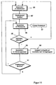
- the control program is formed such that the control unit 36 or the transmitter 37 is fundamentally is in a sleeping state 55. In this sleep state 55 the Transmitter 37 is not activated, so that consequently there is no quiescent current through the activation circuit of the transmitter 37 can flow.
- the control unit 36 or the transmitter 37 Only when the receiver 38 receives a received signal 48, step 48 ', the control unit 36 or the transmitter 37 becomes one Wake-up state 56 in which the transmitter 37 generates a transmission signal 47, Step 57.
- This is preferably a pulse-modulated transmission signal of a specific one Pattern. Alternatively, it can also be a sinusoidal modulation.
- Essential is that the transmission signal 47 has a pattern so that after reflection thereof a received signal 48 is detected on a hand moved in the vicinity of the lamp that is in the control unit 36 in accordance with the transmission signal 47 can be checked.
- the control unit If the correspondence or correlation between the Transmitted signal 47 and the received signal 48 detected, it is the received signal 48 around the reflected transmission signal 47 and not around extraneous light, see above that after this check 58 the control unit is in the activation state 59 is transferred. In this activation state 59, the control signal 53 is sent to the Light source 54 emitted and the light source after a predetermined delay time 54 turned off, step 60.
- Step 61 the transmitter 37 is returned to the wake-up state 56, which is the Sends another transmission signal 57. After sending out this test pattern the decision is made again as to whether one actually brought near the lamp Body means an extension of the operating state of the lamp. If no reception signal is detected within the switch-on time of the light source 54, the control unit returns to the sleep state after the delay time has expired 55 offset.
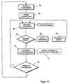
- control unit 62 including the transmitter 37 and the receiver 38 in a sleep state 63 as the initial state.
- a functional element 64 for example by folding down a sun visor of the Vehicle, the control unit 62 is placed in an alarm state 65, in which the Transmitter 37 is driven to generate a transmission signal.
- a check 67 is carried out to determine whether the received signal is actually is the reflected transmission signal.
- the transmitter 37 is put into a sleep state 68, from which it only enters the wake-up state 65 after receipt of a received signal 69 is set back.
- control unit 62 is placed in activation state 70 so that the light source is controlled for a predetermined time interval, 71. If the The control unit takes the functional element 64 back to the initial state 72, 72 62 returns to the sleep state 63, in which neither the transmitter 37 nor the Receiver 38 Consume energy.
- the energy use for controlling the light source can be significantly reduced.
- the control unit 62 after the delay time has expired again in the alarm state 65, so that by continuously sending the transmission signal, the authenticity of the reception signal can be checked.
- control unit 62 can also use an interior monitoring device of the vehicle are set to wake-up state 65. So that the operation the control unit 62 depending on other electrical or mechanical Sizes take place that could be connected with the lamp.
- control unit in the wake-up state 56, 65 can also by the Hand-placed infrared radiation brought near the lamp itself become.
- the sensitivity of the receiver 38 is infrared radiation adapted, after detecting this received signal the one described above Operation to check the authenticity of the same is carried out. Hereby a response of the lamp due to an interference signal is effectively avoided.
Landscapes
- Physics & Mathematics (AREA)
- Engineering & Computer Science (AREA)
- Mechanical Engineering (AREA)
- General Physics & Mathematics (AREA)
- Optics & Photonics (AREA)
- Arrangements Of Lighting Devices For Vehicle Interiors, Mounting And Supporting Thereof, Circuits Therefore (AREA)
- Switches Operated By Changes In Physical Conditions (AREA)
Abstract
Description
- Figur 1:
- Eine Seitenansicht einer Leuchte für Fahrzeuginnenräume mit einer an einem Reflektor angeordneten Reflexionslichtschranke,
- Figur 2:
- eine Seitenansicht einer Leuchte für Fahrzeuginnenräume mit einem zwischen Lichtquelle und Lichtleiter angeordneten teildurchlässigen Spiegel,
- Figur 3:
- eine Seitenansicht einer Leuchte für Fahrzeuginnenräume mit einer an der Rückseite eines Reflektors angeordneten Reflexionslichtschranke,
- Figur 4:
- eine Seitenansicht einer Leuchte für Fahrzeuginnenräume mit einer Reflexionslichtschranke, die über einen separaten Lichtleiter mit einem Lichtaustritt verbunden ist,
- Figur 5:
- eine Seitenansicht einer Leuchte für Fahrzeuginnenräume mit einem Sender und einem Empfänger einer Reflexionslichtschranke, die über separate Lichtleiter mit einem Lichtaustritt verbunden sind,
- Figur 6:
- einen schematischen Teilschnitt einer Leuchte für Fahrzeuginnenräume mit einer an der Rückseite eines Reflektors angeordneten Reflexionslichtschranke, wobei ein Sender und ein Empfänger über jeweils einen zusätzlichen Lichtleiter zu einer Lichteintrittsfläche eines Lichtleiters gekoppelt sind, entlang der Linie VI - VI gemäß Figur 7,
- Figur 7:
- eine Vorderansicht einer Leuchte gemäß Figur 6,
- Figur 8:
- eine schematische Seitenansicht eines Bestandteils einer Leuchte mit einem gemeinsamen zusätzlichen Lichtleiter für einen Sender und einen Empfänger,
- Figur 9:
- ein Blockschaltbild von elektrischen Baueinheiten für eine Leuchte,
- Figur 10:
- eine Ansteuerschaltung für einen Sender als Teil einer Steuereinheit,
- Figur 11:
- ein Flußdiagramm eines Steuerprogramms für eine Leuchte nach einem ersten Ausführungsbeispiel und
- Figur 12:
- ein Flußdiagramm eines Steuerprogramms einer Leuchte nach einem zweiten Ausführungsbeispiel.
Claims (27)
- Leuchte für Fahrzeuginnenräume mit einer Lichtquelle, einem Lichtaustritt und einem die Lichtquelle schaltenden optischen Sensor, dadurch gekennzeichnet, daß der optische Sensor einen Sender (11, 11', 11'', 11''', 37) und einen Empfänger (16, 16', 16'', 16''', 38) aufweist zur Bildung einer Reflexionslichtschranke, wobei der Sender (11, 11', 11'', 11''', 37) ein Sendesignal (47) über eine Auskoppelstelle (51) der Leuchte abstrahlt, das bei Annäherung eines Körpers an die Auskoppelstelle (51) an demselben reflektiert wird und zumindest teilweise über eine Einkoppelstelle (52) auf den Empfänger (16, 16', 16'', 16''', 38) leitbar ist.
- Leuchte nach Anspruch 1, dadurch gekennzeichnet, daß die Einkoppelstelle (52) und die Auskoppelstelle (51) einstückig miteinander verbunden sind.
- Leuchte nach Anspruch 1 oder 2, dadurch gekennzeichnet, daß zwischen der Lichtquelle (2) und der Einkoppel- und Auskoppelstelle ein Lichtleiter (4) angeordnet ist, der an seinem der Lichtquelle (2) zugewandten ersten Ende (6) eine Lichteintrittsfläche (7) aufweist, in die das Licht der Lichtquelle (2) eingekoppelt wird, und daß die Lichtquelle (2) von einem Reflektor (3, 3', 3'') umgeben ist, der das Licht der Lichtquelle (2) bündelt und in die Lichteintrittsfläche (7) einkoppelt.
- Leuchte nach einem der Ansprüche 1 bis 3, dadurch gekennzeichnet, daß die Einkoppel- (52) und/oder Auskoppelstelle (51) des Empfängers (38) bzw. des Senders (37) einen Lichtaustritt (9) des Lichtleiters (4) bilden.
- Leuchte nach einem der Ansprüche 1 bis 4, dadurch gekennzeichnet, daß der optische Sender (11, 11', 11'', 11''') als Infrarot-Leuchtdiode (12) ausgebildet ist.
- Leuchte nach einem der Ansprüche 1 bis 5, dadurch gekennzeichnet, daß der Empfänger (16, 16', 16'', 16''') als Infrarot-Fotodiode (17) ausgebildet ist.
- Leuchte nach einem der Ansprüche 1 bis 5, dadurch gekennzeichnet, daß der Empfänger (16, 16', 16'', 16''') als Infrarot-Fototransistor ausgebildet ist.
- Leuchte nach einem der Ansprüche 1 bis 7, dadurch gekennzeichnet, daß Sender (11) und Empfänger (16) am Reflektor (3) der Lichtquelle (2) so positioniert sind, daß einerseits eine möglichst geringe Reflektorfläche benötigt wird und andererseits Sender (11) und Empfänger (16) auf die Lichteintrittsfläche (7) fokussiert sind.
- Leuchte nach einem der Ansprüche 1 bis 7, dadurch gekennzeichnet, daß zwischen Lichtquelle (2) und Lichteintrittsfläche (7) ein teildurchlässiger Spiegel (20) angeordnet ist, über den Sender (11') und Empfänger (16') auf die Lichteintrittsfläche (7) fokussiert sind.
- Leuchte nach einem der Ansprüche 1 bis 7, dadurch gekennzeichnet, daß Sender (11'') und Empfänger (16'') auf der der Lichtquelle (2) abgewandten Rückseite (22) des Reflektors (3'') angeordnet sind und daß der Reflektor (3'') für Infrarotstrahlung durchlässig ist, so daß für die Infrarotstrahlung Sender (11'') und Empfänger (16'') auf die Lichteintrittsfläche (7) fokussiert sind.
- Leuchte nach einem der Ansprüche 1 bis 7, dadurch gekennzeichnet, daß Sender (11''') und Empfänger (16''') über mindestens einen zusätzlichen Lichtleiter (24, 25) mit dem Lichtaustritt (9) verbunden sind.
- Leuchte nach einem der Ansprüche 1 bis 11, dadurch gekennzeichnet, daß der Sender (11, 11', 11'', 11''') und Empfänger (16, 16', 16'', 16''') zusammen mit einer Steuereinheit (36) auf einer gemeinsamen Leiterplatte (35) positioniert sind, wobei die Leiterplatte (35) auf einer der Lichtquelle (2, 31) abgewandten Rückseite (22) des Reflektors (3'') angeordnet ist.
- Leuchte nach einem der Ansprüche 1 bis 12, dadurch gekennzeichnet, daß in dem Reflektor (32) mindestens ein Durchbruch (41) vorgesehen ist, durch den jeweils ein zusätzlicher Lichtleiter (39) hindurchragt.
- Leuchte nach einem der Ansprüche 1 bis 13, dadurch gekennzeichnet, daß die Lichtquelle (2) mit der Steuereinheit (36) gekoppelt ist, in der das Ansteuersignal (53) für die Lichtquelle (2) und das Ansteuersignal für den Sender (37) zur Abstrahlung eines modulierten Sendesignals (47) erzeugt wird.
- Leuchte nach einem der Ansprüche 1 bis 14, dadurch gekennzeichnet, daß der das Licht führende Lichtleiter (4) und/ oder der das Sendesignal führende Lichtleiter (24, 25) und/ oder der das Empfängersignal führende Lichtleiter (24, 25) einstückig mit einer Abdeckscheibe (46) der Leuchte verbunden ist und daß der Lichtleiter (4, 24, 25) senkrecht zu der Abdeckscheibe ausgerichtet ist.
- Leuchte nach einem der Ansprüche 1 bis 15, dadurch gekennzeichnet, daß die Lichtquelle (2) als Leuchtdiode ausgebildet ist, in die von der Steuereinheit (36) das modulierte Sendesignal einprägbar ist, wobei das Lichtsignal und das Sendesignal über denselben Lichtleiter in die Umgebung ausgekoppelt wird.
- Leuchte nach einem der Ansprüche 1 bis 16, dadurch gekennzeichnet, daß die Lichtleiter (4, 24, 25) als faseroptische Lichtleiter ausgebildet sind.
- Verfahren zum Steuern eine Leuchte für Fahrzeuginnenräume, wobei ein die Leuchte steuerndes Steuersignal in Abhängigkeit von einem durch einen optischen Sensor gelieferten Sensorsignal in einer der Leuchte zugeordneten Steuereinheit erzeugt wird, dadurch gekennzeichnet,
daß von einem Sender (11, 11', 11'', 11''', 37) des optischen Sensors ein Mustersignal (47) erzeugt und einer Auskoppelstelle (51) der Leuchte zugeführt wird, daß über eine Einkoppelstelle (52) der Leuchte ein Empfangssignal (48) zu einem Empfänger (16, 16', 16'', 16''', 38) des optischen Sensors geleitet wird, daß das Empfangssignal (48) mit dem von dem Sender (37) erzeugten Mustersignal (47) verglichen wird, so daß das Empfangssignal (48) als ein an ein in der Nähe der Auskoppelstelle (51) gehaltener Körper reflektiertes Reflexionssignal erkannt werden kann, und daß bei Vorliegen einer Übereinstimmung des Empfangssignals (48) mit dem Mustersignal (47) das Steuersignal (53) generiert wird zum Ansteuern der Lichtquelle (54). - Verfahren nach Anspruch 18, dadurch gekennzeichnet, daß das Sendesignal (47) als moduliertes Sendesignal von dem Sender (11, 11', 11'', 11''', 37) abgestrahlt wird.
- Verfahren nach Anspruch 18 oder 19, dadurch gekennzeichnet, daß das Sendesignal (47) als impulsmoduliertes Sendesignal von dem Sender (11, 11', 11'', 11''') abgestrahlt wird.
- Verfahren zum Steuern einer Leuchte für Fahrzeuginnenräume, wobei ein die Leuchte steuerndes Steuersignal in Abhängigkeit von einem durch einen optischen Sensor gelieferten Sensorsignal in einer der Leuchte zugeordneten Steuereinheit erzeugt wird, dadurch gekennzeichnet, daß sich die Steuereinheit (36) in einem energiesparenden Schlafzustand befindet und erst dann in einen ein Mustersignal (47) abgebenden Weckzustand übergeht, wenn ein Empfangssignal (48) in einem Empfänger (38) detektiert wird, daß in dem Weckzustand der Steuereinheit (36) das Mustersignal (47) von einem Sender (37) abgestrahlt wird und anschließend das von dem Empfänger (38) detektierte Empfangssignal (48) auf Übereinstimmung mit dem gesendeten Mustersignal (47) überprüft wird zur Erkennung eines in der Nähe einer Auskoppelstelle positionierten Körpers und daß in dem Aktivierungszustand der Steuereinheit (36) ein Steuersignal (53) generiert wird zum Ansteuern der Lichtquelle (54).
- Verfahren nach Anspruch 21, dadurch gekennzeichnet, daß der Aktivierungszustand der Steuereinheit (36) während einer vorgegebenen Einschaltzeit der Lichtquelle (2) aufrechterhalten wird.
- Verfahren nach Anspruch 21 oder 22, dadurch gekennzeichnet, daß in dem Aktivierungszustand der Steuereinheit (36) in Abhängigkeit von dem Vorliegen von Empfangssignalen mindestens ein weiteres korrespondierendes Mustersignal als Sendesignal abgestrahlt wird und das detektierte Empfangssignal auf Übereinstimmung mit dem abgestrahlten Sendesignal überprüft wird zur Generierung eines weiteren, die Einschaltzeit verlängernden Steuersignals für die Lichtquelle.
- Verfahren nach einem der Ansprüche 21 bis 23, dadurch gekennzeichnet, daß bei Feststellung der Nichtübereinstimmung des Empfangssignals mit dem Sendesignal die Steuereinheit (36) unmittelbar von dem Weckzustand in den Schlafzustand versetzt wird.
- Verfahren nach einem der Ansprüche 21 bis 24, dadurch gekennzeichnet, daß die Steuereinheit in Abhängigkeit von dem Vorliegen eines detektierten Empfangssignals in einen Weckzustand überführt wird, in dem das Mustersignal generiert wird.
- Verfahren nach einem der Ansprüche 21 bis 24, dadurch gekennzeichnet, daß die Steuereinheit in Abhängigkeit von dem Bestätigen eines der Leuchte zugeordneten Funktionselementes in einen Weckzustand versetzt wird, in dem das Mustersignal generiert wird.
- Verfahren nach einem der Ansprüche 21 bis 26, dadurch gekennzeichnet, daß das Sendesignal moduliert wird.
Applications Claiming Priority (2)
| Application Number | Priority Date | Filing Date | Title |
|---|---|---|---|
| DE19952795A DE19952795A1 (de) | 1999-11-03 | 1999-11-03 | Leuchte und Verfahren zum Steuern einer Leuchte für Fahrzeuginnenräume |
| DE19952795 | 1999-11-03 |
Publications (3)
| Publication Number | Publication Date |
|---|---|
| EP1097842A2 true EP1097842A2 (de) | 2001-05-09 |
| EP1097842A3 EP1097842A3 (de) | 2004-01-14 |
| EP1097842B1 EP1097842B1 (de) | 2006-09-13 |
Family
ID=7927711
Family Applications (1)
| Application Number | Title | Priority Date | Filing Date |
|---|---|---|---|
| EP00123837A Expired - Lifetime EP1097842B1 (de) | 1999-11-03 | 2000-11-02 | Leuchte und Verfahren zum Steuern einer Leuchte für Fahrzeuginnenräume |
Country Status (2)
| Country | Link |
|---|---|
| EP (1) | EP1097842B1 (de) |
| DE (2) | DE19952795A1 (de) |
Cited By (3)
| Publication number | Priority date | Publication date | Assignee | Title |
|---|---|---|---|---|
| WO2004039631A1 (de) * | 2002-10-31 | 2004-05-13 | Gerd Reime | Einrichtung zur steuerung einer beleuchtung, insbesondere für fahrzeuginnenräume sowie verfahren zu ihrer steuerung |
| ITBL20080013A1 (it) * | 2008-07-09 | 2008-10-08 | Fabrizio Righes | Un sensore infrarosso e un diodo emettitore infrarosso costituenti un sensore di prossimita' e un diodo led a luce visibile, posti in assoluta adiacenza e direttamente nel corpo illuminante, in grado di accendere o spegnere il diodo led a luce visibi |
| EP1995114A1 (de) | 2007-05-25 | 2008-11-26 | Delphi Technologies, Inc. | Leuchte in einem Kraftfahrzeug |
Families Citing this family (9)
| Publication number | Priority date | Publication date | Assignee | Title |
|---|---|---|---|---|
| DE10214198B4 (de) * | 2002-03-29 | 2005-07-07 | Münchner Hybrid Systemtechnik GmbH | Schaltbares Leuchtmittel mit automatischer Notbeleuchtung |
| DE10233139B4 (de) * | 2002-07-20 | 2005-07-07 | Münchner Hybrid Systemtechnik GmbH | Leuchtmittel mit einem sensitiven Schalter |
| DE10258497B4 (de) * | 2002-11-29 | 2005-02-10 | Daimlerchrysler Ag | Fahrzeugscheinwerfer zur Beleuchtung der Fahrzeugumgebung und Anordnung zur Verbesserung der Sicht mit solchen Fahrzeugscheinwerfern |
| DE102005005411B4 (de) * | 2005-02-05 | 2022-12-22 | Volkswagen Ag | Kraftfahrzeug mit einem Bedienelement |
| DE102007013627A1 (de) * | 2007-03-19 | 2008-09-25 | Hella Kgaa Hueck & Co. | Innenleuchte für ein Fahrzeug |
| DE102008014143B4 (de) * | 2008-03-14 | 2011-05-12 | Wilke, Hans-Jürgen, Dipl.-Ing. | Beleuchtungssystem |
| DE102010043296B4 (de) * | 2010-11-03 | 2020-10-08 | Lisa Dräxlmaier GmbH | Lichtemittermodul mit Umlenkoptik |
| DE102010043295B4 (de) * | 2010-11-03 | 2020-10-08 | Lisa Dräxlmaier GmbH | Lichtemittermodul |
| DE102017001519B4 (de) | 2017-02-15 | 2019-01-31 | Audi Ag | Formteil |
Citations (2)
| Publication number | Priority date | Publication date | Assignee | Title |
|---|---|---|---|---|
| DE19603025C2 (de) | 1995-05-02 | 1997-03-20 | Hermann Leber | Beleuchtungsvorrichtung zur Einspeisung von Licht in Lichtleitfasern |
| DE19652095A1 (de) | 1996-12-14 | 1998-06-18 | Hella Kg Hueck & Co | Leseleuchte |
Family Cites Families (1)
| Publication number | Priority date | Publication date | Assignee | Title |
|---|---|---|---|---|
| DE3916865C1 (en) * | 1989-05-24 | 1990-05-31 | Mathias Dipl.-Ing. 8000 Muenchen De Hoermann | Contactless switch controlled by IR - uses proximity sensor with reflex light scanner clocked by oscillator |
-
1999
- 1999-11-03 DE DE19952795A patent/DE19952795A1/de not_active Withdrawn
-
2000
- 2000-11-02 EP EP00123837A patent/EP1097842B1/de not_active Expired - Lifetime
- 2000-11-02 DE DE50013461T patent/DE50013461D1/de not_active Expired - Lifetime
Patent Citations (2)
| Publication number | Priority date | Publication date | Assignee | Title |
|---|---|---|---|---|
| DE19603025C2 (de) | 1995-05-02 | 1997-03-20 | Hermann Leber | Beleuchtungsvorrichtung zur Einspeisung von Licht in Lichtleitfasern |
| DE19652095A1 (de) | 1996-12-14 | 1998-06-18 | Hella Kg Hueck & Co | Leseleuchte |
Cited By (4)
| Publication number | Priority date | Publication date | Assignee | Title |
|---|---|---|---|---|
| WO2004039631A1 (de) * | 2002-10-31 | 2004-05-13 | Gerd Reime | Einrichtung zur steuerung einer beleuchtung, insbesondere für fahrzeuginnenräume sowie verfahren zu ihrer steuerung |
| US7221271B2 (en) | 2002-10-31 | 2007-05-22 | Gerd Reime | Device for controlling lighting for the interiors of automotive vehicles and method for controlling said device |
| EP1995114A1 (de) | 2007-05-25 | 2008-11-26 | Delphi Technologies, Inc. | Leuchte in einem Kraftfahrzeug |
| ITBL20080013A1 (it) * | 2008-07-09 | 2008-10-08 | Fabrizio Righes | Un sensore infrarosso e un diodo emettitore infrarosso costituenti un sensore di prossimita' e un diodo led a luce visibile, posti in assoluta adiacenza e direttamente nel corpo illuminante, in grado di accendere o spegnere il diodo led a luce visibi |
Also Published As
| Publication number | Publication date |
|---|---|
| DE50013461D1 (de) | 2006-10-26 |
| EP1097842A3 (de) | 2004-01-14 |
| DE19952795A1 (de) | 2001-05-10 |
| EP1097842B1 (de) | 2006-09-13 |
Similar Documents
| Publication | Publication Date | Title |
|---|---|---|
| EP1097842B1 (de) | Leuchte und Verfahren zum Steuern einer Leuchte für Fahrzeuginnenräume | |
| EP0981470B1 (de) | Optischer sensor | |
| EP1424252B1 (de) | Optischer Sensor | |
| EP1558465B1 (de) | Einrichtung zur steuerung einer beleuchtung, insbesondere für fahrzeuginnenräume sowie verfahren zu ihrer steuerung | |
| DE69920330T2 (de) | Fahrzeugaussenspiegel mit Signalleuchte | |
| EP2471688B1 (de) | Außenliegendes Montagebauteil für ein Fahrzeug mit einem Lichtmodul | |
| EP3025908B1 (de) | Vorrichtung mit aussenbewegungssensor und leuchtmarkierung für ein kraftfahrzeug | |
| WO2001005626A1 (de) | Lichtempfindliche sensoreinheit, insbesondere zum automatischen schalten von beleuchtungseinrichtungen | |
| DE102016118471A1 (de) | Erfassungsvorrichtung für ein Kraftfahrzeug, Anbauteil sowie Kraftfahrzeug | |
| EP3210826A1 (de) | Türgriff | |
| EP1850481B1 (de) | Leuchtmittel mit mehreren LEDs und einem sensitiven Schalter | |
| DE102007013627A1 (de) | Innenleuchte für ein Fahrzeug | |
| EP2052911B1 (de) | Anordnung für Kraftfahrzeuge zum Erkennen der Umgebungshelligkeit während der Fahrt des Kraftfahrzeugs | |
| EP1349279B1 (de) | Optoelektronischer Berührungs- oder Näherungsschalter | |
| EP0120457A2 (de) | Optische Sender- und Empfängervorrichtung | |
| DE19545352B4 (de) | Optischer Empfänger für moduliertes Licht | |
| DE19801915B4 (de) | Sensorsystem | |
| DE102007009038A1 (de) | Sanitärarmatur mit wählbarer Betriebsart | |
| EP1002367B1 (de) | Schaltsystem mit lichtleiter | |
| DE102005042574B4 (de) | Vorrichtung zur Beleuchtung eines Kraftfahrzeugvorfeldes | |
| EP1349436A2 (de) | Schaltbares Leuchtmittel mit Hilfsbeleuchtung | |
| DE8800075U1 (de) | Vorrichtung zum optischen Erfassen des Schaltzustandes eines Schaltgliedes | |
| DE29924958U1 (de) | Optischer Sensor | |
| EP1767415B1 (de) | Überwachungseinrichtung für den Innenraum eines Kraftfahrzeugs | |
| DE102007055497A1 (de) | Optischer Sensor für ein Kraftfahrzeug |
Legal Events
| Date | Code | Title | Description |
|---|---|---|---|
| PUAI | Public reference made under article 153(3) epc to a published international application that has entered the european phase |
Free format text: ORIGINAL CODE: 0009012 |
|
| AK | Designated contracting states |
Kind code of ref document: A2 Designated state(s): AT BE CH CY DE DK ES FI FR GB GR IE IT LI LU MC NL PT SE TR |
|
| AX | Request for extension of the european patent |
Free format text: AL;LT;LV;MK;RO;SI |
|
| PUAL | Search report despatched |
Free format text: ORIGINAL CODE: 0009013 |
|
| AK | Designated contracting states |
Kind code of ref document: A3 Designated state(s): AT BE CH CY DE DK ES FI FR GB GR IE IT LI LU MC NL PT SE TR |
|
| AX | Request for extension of the european patent |
Extension state: AL LT LV MK RO SI |
|
| 17P | Request for examination filed |
Effective date: 20040305 |
|
| AKX | Designation fees paid |
Designated state(s): DE ES FR IT |
|
| RAP1 | Party data changed (applicant data changed or rights of an application transferred) |
Owner name: HELLA KGAA HUECK & CO. |
|
| GRAP | Despatch of communication of intention to grant a patent |
Free format text: ORIGINAL CODE: EPIDOSNIGR1 |
|
| GRAS | Grant fee paid |
Free format text: ORIGINAL CODE: EPIDOSNIGR3 |
|
| GRAA | (expected) grant |
Free format text: ORIGINAL CODE: 0009210 |
|
| AK | Designated contracting states |
Kind code of ref document: B1 Designated state(s): DE ES FR IT |
|
| PG25 | Lapsed in a contracting state [announced via postgrant information from national office to epo] |
Ref country code: IT Free format text: LAPSE BECAUSE OF FAILURE TO SUBMIT A TRANSLATION OF THE DESCRIPTION OR TO PAY THE FEE WITHIN THE PRESCRIBED TIME-LIMIT;WARNING: LAPSES OF ITALIAN PATENTS WITH EFFECTIVE DATE BEFORE 2007 MAY HAVE OCCURRED AT ANY TIME BEFORE 2007. THE CORRECT EFFECTIVE DATE MAY BE DIFFERENT FROM THE ONE RECORDED. Effective date: 20060913 |
|
| REF | Corresponds to: |
Ref document number: 50013461 Country of ref document: DE Date of ref document: 20061026 Kind code of ref document: P |
|
| PG25 | Lapsed in a contracting state [announced via postgrant information from national office to epo] |
Ref country code: ES Free format text: LAPSE BECAUSE OF FAILURE TO SUBMIT A TRANSLATION OF THE DESCRIPTION OR TO PAY THE FEE WITHIN THE PRESCRIBED TIME-LIMIT Effective date: 20061224 |
|
| ET | Fr: translation filed | ||
| PLBE | No opposition filed within time limit |
Free format text: ORIGINAL CODE: 0009261 |
|
| STAA | Information on the status of an ep patent application or granted ep patent |
Free format text: STATUS: NO OPPOSITION FILED WITHIN TIME LIMIT |
|
| 26N | No opposition filed |
Effective date: 20070614 |
|
| PGFP | Annual fee paid to national office [announced via postgrant information from national office to epo] |
Ref country code: IT Payment date: 20071126 Year of fee payment: 8 |
|
| PG25 | Lapsed in a contracting state [announced via postgrant information from national office to epo] |
Ref country code: IT Free format text: LAPSE BECAUSE OF NON-PAYMENT OF DUE FEES Effective date: 20081102 |
|
| PGFP | Annual fee paid to national office [announced via postgrant information from national office to epo] |
Ref country code: DE Payment date: 20091029 Year of fee payment: 10 |
|
| PGFP | Annual fee paid to national office [announced via postgrant information from national office to epo] |
Ref country code: FR Payment date: 20091123 Year of fee payment: 10 |
|
| REG | Reference to a national code |
Ref country code: DE Ref legal event code: R119 Ref document number: 50013461 Country of ref document: DE Effective date: 20110601 Ref country code: DE Ref legal event code: R119 Ref document number: 50013461 Country of ref document: DE Effective date: 20110531 |
|
| REG | Reference to a national code |
Ref country code: FR Ref legal event code: ST Effective date: 20110801 |
|
| PG25 | Lapsed in a contracting state [announced via postgrant information from national office to epo] |
Ref country code: DE Free format text: LAPSE BECAUSE OF NON-PAYMENT OF DUE FEES Effective date: 20110531 |
|
| PG25 | Lapsed in a contracting state [announced via postgrant information from national office to epo] |
Ref country code: FR Free format text: LAPSE BECAUSE OF NON-PAYMENT OF DUE FEES Effective date: 20101130 |