EP1096119B1 - Schalteinheit - Google Patents
Schalteinheit Download PDFInfo
- Publication number
- EP1096119B1 EP1096119B1 EP00121262A EP00121262A EP1096119B1 EP 1096119 B1 EP1096119 B1 EP 1096119B1 EP 00121262 A EP00121262 A EP 00121262A EP 00121262 A EP00121262 A EP 00121262A EP 1096119 B1 EP1096119 B1 EP 1096119B1
- Authority
- EP
- European Patent Office
- Prior art keywords
- flap
- flow cross
- section
- induction system
- switched
- Prior art date
- Legal status (The legal status is an assumption and is not a legal conclusion. Google has not performed a legal analysis and makes no representation as to the accuracy of the status listed.)
- Expired - Lifetime
Links
- 238000002485 combustion reaction Methods 0.000 claims abstract description 9
- 238000007789 sealing Methods 0.000 claims description 12
- 238000000034 method Methods 0.000 claims description 5
- 230000005540 biological transmission Effects 0.000 claims description 3
- 238000001746 injection moulding Methods 0.000 claims description 3
- 230000006698 induction Effects 0.000 claims 11
- 238000006073 displacement reaction Methods 0.000 claims 3
- 230000008878 coupling Effects 0.000 description 2
- 238000010168 coupling process Methods 0.000 description 2
- 238000005859 coupling reaction Methods 0.000 description 2
- 238000011144 upstream manufacturing Methods 0.000 description 2
- 241000881711 Acipenser sturio Species 0.000 description 1
- 230000006978 adaptation Effects 0.000 description 1
- XAGFODPZIPBFFR-UHFFFAOYSA-N aluminium Chemical compound [Al] XAGFODPZIPBFFR-UHFFFAOYSA-N 0.000 description 1
- 229910052782 aluminium Inorganic materials 0.000 description 1
- 238000005266 casting Methods 0.000 description 1
- 238000005520 cutting process Methods 0.000 description 1
- 230000000694 effects Effects 0.000 description 1
- 238000004519 manufacturing process Methods 0.000 description 1
- 239000000463 material Substances 0.000 description 1
- 230000009347 mechanical transmission Effects 0.000 description 1
- 239000003566 sealing material Substances 0.000 description 1
- 238000003860 storage Methods 0.000 description 1
- 230000001360 synchronised effect Effects 0.000 description 1
- 230000007704 transition Effects 0.000 description 1
- 238000003466 welding Methods 0.000 description 1
Images


Classifications
-
- F—MECHANICAL ENGINEERING; LIGHTING; HEATING; WEAPONS; BLASTING
- F02—COMBUSTION ENGINES; HOT-GAS OR COMBUSTION-PRODUCT ENGINE PLANTS
- F02D—CONTROLLING COMBUSTION ENGINES
- F02D9/00—Controlling engines by throttling air or fuel-and-air induction conduits or exhaust conduits
- F02D9/08—Throttle valves specially adapted therefor; Arrangements of such valves in conduits
- F02D9/10—Throttle valves specially adapted therefor; Arrangements of such valves in conduits having pivotally-mounted flaps
- F02D9/1005—Details of the flap
- F02D9/1025—Details of the flap the rotation axis of the flap being off-set from the flap center axis
- F02D9/103—Details of the flap the rotation axis of the flap being off-set from the flap center axis the rotation axis being located at an edge
-
- F—MECHANICAL ENGINEERING; LIGHTING; HEATING; WEAPONS; BLASTING
- F02—COMBUSTION ENGINES; HOT-GAS OR COMBUSTION-PRODUCT ENGINE PLANTS
- F02B—INTERNAL-COMBUSTION PISTON ENGINES; COMBUSTION ENGINES IN GENERAL
- F02B27/00—Use of kinetic or wave energy of charge in induction systems, or of combustion residues in exhaust systems, for improving quantity of charge or for increasing removal of combustion residues
- F02B27/02—Use of kinetic or wave energy of charge in induction systems, or of combustion residues in exhaust systems, for improving quantity of charge or for increasing removal of combustion residues the systems having variable, i.e. adjustable, cross-sectional areas, chambers of variable volume, or like variable means
-
- F—MECHANICAL ENGINEERING; LIGHTING; HEATING; WEAPONS; BLASTING
- F02—COMBUSTION ENGINES; HOT-GAS OR COMBUSTION-PRODUCT ENGINE PLANTS
- F02B—INTERNAL-COMBUSTION PISTON ENGINES; COMBUSTION ENGINES IN GENERAL
- F02B27/00—Use of kinetic or wave energy of charge in induction systems, or of combustion residues in exhaust systems, for improving quantity of charge or for increasing removal of combustion residues
- F02B27/02—Use of kinetic or wave energy of charge in induction systems, or of combustion residues in exhaust systems, for improving quantity of charge or for increasing removal of combustion residues the systems having variable, i.e. adjustable, cross-sectional areas, chambers of variable volume, or like variable means
- F02B27/0205—Use of kinetic or wave energy of charge in induction systems, or of combustion residues in exhaust systems, for improving quantity of charge or for increasing removal of combustion residues the systems having variable, i.e. adjustable, cross-sectional areas, chambers of variable volume, or like variable means characterised by the charging effect
- F02B27/0215—Oscillating pipe charging, i.e. variable intake pipe length charging
-
- F—MECHANICAL ENGINEERING; LIGHTING; HEATING; WEAPONS; BLASTING
- F02—COMBUSTION ENGINES; HOT-GAS OR COMBUSTION-PRODUCT ENGINE PLANTS
- F02B—INTERNAL-COMBUSTION PISTON ENGINES; COMBUSTION ENGINES IN GENERAL
- F02B27/00—Use of kinetic or wave energy of charge in induction systems, or of combustion residues in exhaust systems, for improving quantity of charge or for increasing removal of combustion residues
- F02B27/02—Use of kinetic or wave energy of charge in induction systems, or of combustion residues in exhaust systems, for improving quantity of charge or for increasing removal of combustion residues the systems having variable, i.e. adjustable, cross-sectional areas, chambers of variable volume, or like variable means
- F02B27/0226—Use of kinetic or wave energy of charge in induction systems, or of combustion residues in exhaust systems, for improving quantity of charge or for increasing removal of combustion residues the systems having variable, i.e. adjustable, cross-sectional areas, chambers of variable volume, or like variable means characterised by the means generating the charging effect
- F02B27/0268—Valves
- F02B27/0273—Flap valves
-
- F—MECHANICAL ENGINEERING; LIGHTING; HEATING; WEAPONS; BLASTING
- F02—COMBUSTION ENGINES; HOT-GAS OR COMBUSTION-PRODUCT ENGINE PLANTS
- F02B—INTERNAL-COMBUSTION PISTON ENGINES; COMBUSTION ENGINES IN GENERAL
- F02B31/00—Modifying induction systems for imparting a rotation to the charge in the cylinder
- F02B31/08—Modifying induction systems for imparting a rotation to the charge in the cylinder having multiple air inlets
-
- F—MECHANICAL ENGINEERING; LIGHTING; HEATING; WEAPONS; BLASTING
- F02—COMBUSTION ENGINES; HOT-GAS OR COMBUSTION-PRODUCT ENGINE PLANTS
- F02D—CONTROLLING COMBUSTION ENGINES
- F02D9/00—Controlling engines by throttling air or fuel-and-air induction conduits or exhaust conduits
- F02D9/08—Throttle valves specially adapted therefor; Arrangements of such valves in conduits
- F02D9/10—Throttle valves specially adapted therefor; Arrangements of such valves in conduits having pivotally-mounted flaps
- F02D9/1035—Details of the valve housing
- F02D9/104—Shaping of the flow path in the vicinity of the flap, e.g. having inserts in the housing
-
- F—MECHANICAL ENGINEERING; LIGHTING; HEATING; WEAPONS; BLASTING
- F02—COMBUSTION ENGINES; HOT-GAS OR COMBUSTION-PRODUCT ENGINE PLANTS
- F02D—CONTROLLING COMBUSTION ENGINES
- F02D9/00—Controlling engines by throttling air or fuel-and-air induction conduits or exhaust conduits
- F02D9/08—Throttle valves specially adapted therefor; Arrangements of such valves in conduits
- F02D9/10—Throttle valves specially adapted therefor; Arrangements of such valves in conduits having pivotally-mounted flaps
- F02D9/109—Throttle valves specially adapted therefor; Arrangements of such valves in conduits having pivotally-mounted flaps having two or more flaps
-
- F—MECHANICAL ENGINEERING; LIGHTING; HEATING; WEAPONS; BLASTING
- F02—COMBUSTION ENGINES; HOT-GAS OR COMBUSTION-PRODUCT ENGINE PLANTS
- F02D—CONTROLLING COMBUSTION ENGINES
- F02D9/00—Controlling engines by throttling air or fuel-and-air induction conduits or exhaust conduits
- F02D9/08—Throttle valves specially adapted therefor; Arrangements of such valves in conduits
- F02D9/10—Throttle valves specially adapted therefor; Arrangements of such valves in conduits having pivotally-mounted flaps
- F02D9/109—Throttle valves specially adapted therefor; Arrangements of such valves in conduits having pivotally-mounted flaps having two or more flaps
- F02D9/1095—Rotating on a common axis, e.g. having a common shaft
-
- F—MECHANICAL ENGINEERING; LIGHTING; HEATING; WEAPONS; BLASTING
- F05—INDEXING SCHEMES RELATING TO ENGINES OR PUMPS IN VARIOUS SUBCLASSES OF CLASSES F01-F04
- F05C—INDEXING SCHEME RELATING TO MATERIALS, MATERIAL PROPERTIES OR MATERIAL CHARACTERISTICS FOR MACHINES, ENGINES OR PUMPS OTHER THAN NON-POSITIVE-DISPLACEMENT MACHINES OR ENGINES
- F05C2201/00—Metals
- F05C2201/02—Light metals
- F05C2201/021—Aluminium
-
- Y—GENERAL TAGGING OF NEW TECHNOLOGICAL DEVELOPMENTS; GENERAL TAGGING OF CROSS-SECTIONAL TECHNOLOGIES SPANNING OVER SEVERAL SECTIONS OF THE IPC; TECHNICAL SUBJECTS COVERED BY FORMER USPC CROSS-REFERENCE ART COLLECTIONS [XRACs] AND DIGESTS
- Y02—TECHNOLOGIES OR APPLICATIONS FOR MITIGATION OR ADAPTATION AGAINST CLIMATE CHANGE
- Y02T—CLIMATE CHANGE MITIGATION TECHNOLOGIES RELATED TO TRANSPORTATION
- Y02T10/00—Road transport of goods or passengers
- Y02T10/10—Internal combustion engine [ICE] based vehicles
- Y02T10/12—Improving ICE efficiencies
Definitions
- the invention relates to an intake system of an internal combustion engine according to the preamble of claim 1.
- EP 0 701 057 shows an intake system of an internal combustion engine with several side by side arranged inlet channels and a switching unit for channel shutdown the inlet channels.
- the intake system has switched on and not switched on Flow areas.
- the switched flow cross sections can each with one Flap to be closed. These are the flaps with a single movement unit connected, which outside the non-switched flow cross sections runs.
- From DE 195 04 382 is a switching unit for an intake system with several side by side arranged inlet ports of an internal combustion engine known, the two intake ports for each cylinder, with one channel closed with a flap The other channel is always open.
- the flaps of the lockable Inlet channels are applied to a shaft which is movable via a drive. All flaps of the switching unit are mounted on the same shaft, causing the shaft each inlet channel cuts, even the non-switched channels. This can be leakage currents occur between the switched and non-switched inlet channels, which disturb the charging effect by the vacuum wave.
- Another disadvantage This arrangement is that the wave in the non-switched channels an interference contour forms, whereby the air flow is disturbed and turbulences arise, the Reduce the fill level of the cylinders.
- the object of the invention is an intake system with a switching unit for Channel shutdown of intake ports to create that no leakage between the switched and allows the non-switched flow cross sections and continue Avoiding contours in the non-switched flow cross sections.
- the intake system according to the invention with a plurality of adjacent inlet channels an internal combustion engine is advantageously suitable, a plurality of flow cross sections to close with a switching unit and open as needed, where in the closed state no leakage between the juxtaposed Flow cross sections occurs, and the non-switched flow cross sections have no, caused by the movement unit, sturgeon contours.
- the inlet channels of the intake system can be made in one piece, or from several housing parts be composed. In the multi-part design, the housing parts, e.g. be welded or bolted together.
- the switching unit is an area of the intake system that is connected over at least two and non-switched flow cross sections, flaps and a moving unit features.
- the switched flow cross sections are the areas of the inlet channels, in which flaps are located and the non - switched flow cross sections are the Areas of the inlet ducts, which lie in the height of the switched flow cross sections, but have no flaps.
- This movement unit may e.g. by a single wave or more Damper shafts are formed with a drive. In the process, the parts of the movement unit become always led out of the switched flow cross-section and moved outside of these flow cross sections.
- the non-switched flow cross sections have no contact with the moving unit at any point, whereby no connection between the switched and non-switched flow cross sections exists and thus no leakage can occur.
- To prevent a leakage between to prevent the switched flow cross-sections are in these joints to seal what e.g. can be done with a seal.
- the flap has at least two separate, flap parts, which are each applied to a separate flap shaft.
- the flap shaft can while e.g. lie in an edge region of the flap parts, or be arranged centrally. at a central arrangement of the flap shaft are the flap shaft and the flap parts in the closed, as well as open state in the switched flow cross-section.
- the Damper parts advantageously be formed fluidically, so that the flap parts, which remain in the switched flow cross-section, the least possible air turbulence cause.
- Possible variants here are vaults that the constricted switched flow cross-section and expand again without the streamlines be changed significantly, or demolish.
- a particular embodiment of the invention provides a coupling of the flap shafts with each other.
- the coupling of the flap shafts can by a mechanical transmission take place, which is connected directly to the flap shafts, or by an electronic Control of motors, which drives the flap shafts.
- the flap waves can be moved in the same direction or in opposite directions. In an opposite rotational movement the flap shafts, are only in one area of the intake channel shots for the Provide flap parts, whereby the production of the intake port is simplified. at the co-rotating movement of the flap shafts is a compensation of the occurring Achieved forces, as a flap part down and the other flap part after pans up.
- a particular embodiment is the flap parts and their movement units in the open state to remove from the flow cross-section, thereby to achieve a better flow behavior.
- the flap parts can be removed from the Flow channel can be pulled out or-rotated. When pulling out the flap parts from the switched flow cross-section, make sure that no Leakage occurs. This can be achieved by exact tolerances.
- Another Possibility to remove the flap from the flow cross section is turning the Flap parts in this provided recordings in the flow channel. This will be Interference contours in, and leakage currents between the switched flow cross sections avoided.
- sealing surfaces are provided on the flap.
- the sealing surfaces can both the flap against the flow cross section, as well as the flap parts seal with each other. They can be smooth or geometric stepped surfaces provide a seal such as e.g. create a labyrinth seal.
- a Another way to create sealing surfaces is to have sealing material to apply the flap. The sealing surfaces are designed so that they the flow channel Seal according to the respective state. When closed seals the Flip the flow cross section and in the open state, the wall of the inlet channel from. The use of seals on the sealing surfaces is another way that To produce tightness of the flap in the flow cross-section.
- a particular embodiment of the invention provides a staggered arrangement of the switched to the non-switched flow cross sections.
- everyone can switched flow cross-sections lie on one axis, causing the flaps on a continuous shaft can be attached and thus all the flaps synchronously to be moved.
- a torsionally rigid material such as e.g. aluminum to choose.
- the non-switched flow cross sections can also on a Axis lie, but to a sufficient distance of the channel wall of the Movement unit is to be respected, thereby no interference contours in the non-switched To obtain channel or weaken the channel wall too much, so that in operation, the channel wall breaks through.
- the intake ports on the cylinder head are usually arranged in a row is it is advantageous, depending on a switched and a non-switched flow cross-section to provide for a cylinder and this in front of the cylinder in one, lying on one axis Merge row.
- the merging of the two flow cross sections in a row in front of the cylinder head is a space-optimal variant, the one allow easy switching of the flaps with a shaft, without the air flow in the non-switched flow cross sections are affected by interference contours.
- An advantageous embodiment of the inventive concept represents the movement of the flap with a gearbox.
- the gearbox is then part of the movement unit.
- the shaft can be moved with the gear, creating special flap positions or movements be achieved.
- the individual flap parts connected by the gear. This allows the flap parts on the transmission with to be moved by a single drive.
- the flap waves can be in a given Gear ratio operated.
- gear ratio unequal 1: 1 flow variants can be generated by a flap part faster or opens wider than the other flap part.
- transmissions are also conceivable which move the flaps translationally, whereby the flaps from the flow cross-section be removed.
- toothed or lever gear can be used.
- the flap in a nozzle are introduced, which encloses the switched flow cross-section.
- This Nozzle is designed so that it is introduced as a preassembled unit in the intake system can be, and thus close the flap as a valve flow channel or can open.
- the neck he can use the entire Form switching element, which is introduced as a pre-assembled module in the intake system becomes.
- the flap parts and the nozzle in injection molding technique making use of the advantages of the assembly injection molding technique and low Tolerances and optimal fit can be realized and thus almost no leakage occurs.
- a particular embodiment of the invention provides the use of the switching unit in a, substantially rectangular flow channel before.
- the storage the flaps by molded journal or by an introduced axis in the edge areas take place.
- the flap parts in the provided recordings are rotated on the wall of the flow channel.
- a switching unit 10 is shown in section through an inlet channel 11, wherein in an intake multiple inlet channels 11 are arranged side by side (not shown here).
- this switching unit 10 is rectangular Inlet channels 11, flaps 12, flap shafts 23 and a movement unit 13 (not shown, see Figure 4).
- the inlet channel 11 is made of an upper and a lower Channel piece 14, 15 formed.
- the flap 12 is replaced by a first and a second Flap part 16, 17 formed, which are introduced into the inlet channel 11.
- the channel pieces 14, 15 each have a, on the circumference integral wall 18, the bearing and sealing points 19 for the flap parts 16, 17 and which encloses a rectangular flow cross-section 20, which is closed or released by the flap 12.
- the wall 18 the inlet channel 11 has receptacles 21, in which the flap parts 16, 17 pivoted can be to represent no interference contours in the flow cross-section 20.
- the switching unit 10 is designed so that the flap parts 16, 17 in the inlet channel 11 in the closed position sealing contact, this show the flap parts 16, 17 beveled sealing surfaces 22 on.
- the flap parts 16, 17 are so in the Lagerund Sealing points 19 of the channel pieces 14, 15 introduced that in these areas no Leakage currents occur.
- the switching unit 10 is shown in Figure 1 in section in the open position.
- the flap parts 16, 17 in the receptacles 21 provided for this purpose rotated by a co-rotation and lie against the wall 18 at. Thereby There are no interference contours in the flow cross-section 20, the course of the streamlines affect.
- the switching unit 10 with counter-rotating flap parts 16, 17 in Section represented by an inlet channel 11.
- the shots 21 for the flap parts 16, 17 housed only in the upper channel piece 14. Camps- and sealing points 19 of the flap parts 16, 17, however, are located in the lower Channel piece 15.
- the flap parts 16, 17 are designed so that the Damper parts 16, 17 secure themselves.
- the flap 12 acts Ambient pressure on the flap parts 16, 17, this compresses even more and so a better tightness of the flap 12 causes.
- you open the flap 12 the Flap parts 16, 17 moves in the opposite direction of rotation and applied to the wall 18. As a result, no interference contours remain in the flow cross-section 20.
- a movement unit 13 is shown in half section, one against each other extending movement of the flap parts 16, 17, by the same direction of rotation the flap waves, causes (similar to Figure 2).
- the flap parts 16, 17 are in the Lagerund Seal 19 is rotatably mounted and connected to levers 24, 25, 26.
- the movement unit 13 includes a short left lever arm 24, a long lever arm 25 and a short right lever arm 26.
- the left lever arm 24 is with the first flap part 16 and the right lever arm 26 is connected to the second flap part 17.
- the two Lever arms 24, 26 are connected by the long lever arm 25.
- the connection of Lever arms 24, 25, 26 is designed so that they can move in rotation to each other.
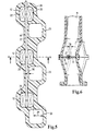
- FIG. 5 a section of an intake system is shown in section, the offset has flow cross sections 20 arranged to each other.
- the flaps 12 of the switched Flow cross sections 20 are on a single, continuous shaft 27th attached.
- the flaps 12 by e.g. Laser welding on the shaft 27 attached.
- the flaps 12 But can also be secured by rivets or screws on the shaft 27.
- the Bearing points 19 ' are designed so that no leakage between the switched flow cross sections 20 is created. In various designs are in these areas Gaskets applied to the shaft 27.
- the non-switched flow cross sections 20 have no disturbing contours generated by the shaft 27 or flaps 12.
- the staggered flow cross-sections 20 can in the staggered design be guided without merging to the cylinders.
- Here is an adaptation the cylinder head flange to the intake system required.
- the switching unit is shown in section along the section line A-A according to Figure 5.
- the section extends along an inlet channel 11 arranged offset switched flow cross-sections 20.
- the first share parallel inlet channels 11 in the region of the flaps 12 in a staggered arrangement on.
- the largest offset 29 between the switched and the non-switched flow cross-sections 20 In the area of the flaps 12, the largest offset 29 between the switched and the non-switched flow cross-sections 20.
- the offset 29 of Flow cross sections 20 is just chosen so large that the shaft 27 on the not switched flow cross-section 20 is passed without cutting it, However, care must be taken to a sufficient wall thickness 30 to a Breaking the shaft 27 during operation to avoid.
- the inlet channels 11 are after the area of the flaps 12 again merged in parallel, with no adjustment the cylinder head flange is required. The transition from the parallel arranged Inlet channels 11 to the staggered arrangement takes place in flow-optimized arches, whereby the flow lines of the air are almost not
Landscapes
- Engineering & Computer Science (AREA)
- Chemical & Material Sciences (AREA)
- Combustion & Propulsion (AREA)
- Mechanical Engineering (AREA)
- General Engineering & Computer Science (AREA)
- Characterised By The Charging Evacuation (AREA)
- Control Of Stepping Motors (AREA)
- Oscillators With Electromechanical Resonators (AREA)
- Vehicle Body Suspensions (AREA)
- Exhaust Gas After Treatment (AREA)
- Multiple-Way Valves (AREA)
Description
- Figur 1
- eine geschlossene gegenläufige Schalteinheit in Schnitt,
- Figur 2
- eine geöffnete gegenläufige Schalteinheit im Schnitt,
- Figur 3
- eine geschlossene gleichläufige Schalteinheit im Schnitt,
- Figur 4
- eine schematisch dargestellte Bewegungseinheit,
- Figur 5
- eine Schalteinheit im Schnitt mit versetzt angeordneten Kanälen und
- Figur 6
- eine Schalteinheit im Schnitt.
Claims (10)
- Ansaugsystem einer Brennkraftmaschine mit mehreren nebeneinander angeordneten Einlasskanälen (11) und Schalteinheit (10) zur Kanalabschaltung der Einlasskanäle (11) einer Brennkraftmaschine, welches mindestens über zwei geschaltete und einen nicht geschalteten Strömungsquerschnitt (20) verfügt und wobei die geschalteten Strömungsquerschnitte (20) mit jeweils einer Klappe (12) versehen sind und durch eine einzige Bewegungseinheit öffen- und schließbar sind, wobei die Bewegungseinheit außerhalb des nicht geschalteten Strömungsquerschnittes (20) verläuft, dadurch gekennzeichnet, daß die Klappe (12) mindestens zwei voneinander getrennte Klappenteile (16, 17) aufweist, die auf je einer Klappenwelle (23) aufgebracht sind, wobei sich die Klappenteile im Einlaßkanal bei geschlossener Stellung dichtend berühren.
- Ansaugsystem nach Anspruch 1 dadurch gekennzeichnet, daß die Klappenwellen (23) hinsichtlich der Klappenstellung miteinander gekoppelt sind.
- Ansaugsystem nach einem der vorangehenden Ansprüche, dadurch gekennzeichnet, daß sich die Klappe (12) im geöffneten Zustand außerhalb des Strömungsquerschnittes (20) befindet.
- Ansaugsystem nach einem der vorangehenden Ansprüche, dadurch gekennzeichnet, daß die Klappe (12) Dichtflächen (22) aufweist
- Ansaugsystem nach einem der vorangehenden Ansprüche, dadurch gekennzeichnet, daß die geschalteten Strömungsquerschnitte (20) zu den nicht geschalteten Strömungsquerschnitten (20) versetzt angeordnet sind.
- Ansaugsystem nach Anspruch 5, dadurch gekennzeichnet, daß je ein geschalteter und ein nicht geschalteter Strömungsquerschnitt (20) für je einen Zylinder vorgesehen sind.
- Ansaugsystem nach einem der vorangehenden Ansprüche, dadurch gekennzeichnet, daß die Klappe (12) durch ein Getriebe, welches Teil der Bewegungseinheit ist, bewegbar ist.
- Ansaugsystem nach einem der vorangehenden Ansprüche, dadurch gekennzeichnet, daß die Klappe (12) in einen Stutzen eingebracht ist, wobei der Stutzen den Strömungsquerschnitt (20) umschließt und in das Ansaugsystem einbringbar ist.
- Ansaugsystem nach Anspruch 8, dadurch gekennzeichnet, daß die Klappe (12) und der Stutzen in Montagespritzguß hergestellt ist.
- Ansaugsystem nach einem der vorangehenden Ansprüche, dadurch gekennzeichnet, daß die Klappe (12) in einen, im wesentlichen rechteckförmigen, Strömungsquerschnitt (20) eingebracht ist.
Applications Claiming Priority (2)
| Application Number | Priority Date | Filing Date | Title |
|---|---|---|---|
| DE19951412 | 1999-10-26 | ||
| DE19951412A DE19951412A1 (de) | 1999-10-26 | 1999-10-26 | Schalteinheit |
Publications (3)
| Publication Number | Publication Date |
|---|---|
| EP1096119A2 EP1096119A2 (de) | 2001-05-02 |
| EP1096119A3 EP1096119A3 (de) | 2002-02-06 |
| EP1096119B1 true EP1096119B1 (de) | 2003-12-10 |
Family
ID=7926840
Family Applications (1)
| Application Number | Title | Priority Date | Filing Date |
|---|---|---|---|
| EP00121262A Expired - Lifetime EP1096119B1 (de) | 1999-10-26 | 2000-10-05 | Schalteinheit |
Country Status (5)
| Country | Link |
|---|---|
| US (1) | US6341589B1 (de) |
| EP (1) | EP1096119B1 (de) |
| JP (1) | JP2001152989A (de) |
| AT (1) | ATE256249T1 (de) |
| DE (2) | DE19951412A1 (de) |
Families Citing this family (6)
| Publication number | Priority date | Publication date | Assignee | Title |
|---|---|---|---|---|
| DE19918777A1 (de) * | 1999-04-24 | 2000-10-26 | Mann & Hummel Filter | Schaltklappenverband aus montagegespritzten Schaltklappen oder Klappenmodulen |
| DE10215667A1 (de) * | 2002-04-10 | 2003-11-06 | Pierburg Gmbh | Aufladesystem für Brennkraftmaschinen |
| DE10220340A1 (de) * | 2002-05-07 | 2003-11-27 | Siemens Ag | Klappenventil für Luftansaugkanal einer Brennkraftmaschine |
| DE10336976B4 (de) * | 2003-08-12 | 2005-08-18 | Pierburg Gmbh | Ventilvorrichtung für eine Verbrennungskraftmaschine |
| US8028677B2 (en) * | 2008-09-09 | 2011-10-04 | Mark Iv Systemes Moteurs Usa, Inc. | Assembly and method for controlling an air intake runner |
| DE102011008599A1 (de) * | 2011-01-14 | 2012-07-19 | GM Global Technology Operations LLC (n. d. Gesetzen des Staates Delaware) | Ventilanordnung im Abgastrakt einer Verbrennungskraftmaschine |
Family Cites Families (22)
| Publication number | Priority date | Publication date | Assignee | Title |
|---|---|---|---|---|
| JPS53133026U (de) * | 1977-03-30 | 1978-10-21 | ||
| IT1163075B (it) * | 1983-02-02 | 1987-04-08 | Alfa Romeo Auto Spa | Impianto di aspirazione per un motore a c.i.dotato di piu' valvole di aspirazione |
| US4703734A (en) * | 1985-03-06 | 1987-11-03 | Nissan Motor Co., Ltd. | Multi-valve internal combustion engine |
| DE3704717A1 (de) * | 1986-02-25 | 1987-08-27 | Volkswagen Ag | Mehrzylinder-brennkraftmaschine mit mitteln zur drallerhoehung |
| DE3633509A1 (de) * | 1986-10-02 | 1988-04-14 | Porsche Ag | Brennkraftmaschine mit wenigstens zwei einlassventilen pro zylinder |
| JPS63111227A (ja) * | 1986-10-30 | 1988-05-16 | Mazda Motor Corp | エンジンの吸気装置 |
| US4834048A (en) * | 1987-05-20 | 1989-05-30 | Volkswagen Ag | Internal combustion engine having at least two inlet valves per combustion chamber |
| DE3865011D1 (de) * | 1987-10-07 | 1991-10-24 | Keith Gordon Hall | Ansauganlage fuer ein brennkraftmaschine. |
| US4850796A (en) * | 1988-05-25 | 1989-07-25 | Sundstrand Corporation | Centrifugal pump with splitter vane/shut-off valve system |
| JPH0228530U (de) * | 1988-08-16 | 1990-02-23 | ||
| DE3843509C2 (de) * | 1988-12-23 | 1993-11-18 | Daimler Benz Ag | Ansaugsystem für eine Brennkraftmaschine |
| DE3909837A1 (de) * | 1989-03-25 | 1990-09-27 | Audi Ag | Saugrohranlage fuer eine mehrzylinder-brennkraftmaschine |
| DE4018612C2 (de) * | 1990-06-11 | 2003-04-30 | Audi Ag | Ansaugsystem für eine Mehrzylinder-Brennkraftmaschine |
| US5239960A (en) * | 1991-07-30 | 1993-08-31 | Mazda Motor Corporation | Engine induction system provided with a mechanical supercharger |
| FR2724418B1 (fr) * | 1994-09-09 | 1997-01-17 | Magneti Marelli France | Tubulure d'admission d'air a volets pivotants pour moteur a combustion interne |
| DE19503771A1 (de) * | 1995-02-04 | 1996-08-08 | Mann & Hummel Filter | Saugmodul |
| DE19504382A1 (de) * | 1995-02-10 | 1996-08-14 | Mann & Hummel Filter | Ansaugsystem |
| JPH08277717A (ja) * | 1995-04-06 | 1996-10-22 | Du Pont Kk | 吸気制御バルブを備えた樹脂吸気系 |
| US5711261A (en) * | 1995-05-31 | 1998-01-27 | Gambardella; C. Bruce | Intake system for V-type engine |
| TW344015B (en) * | 1996-08-12 | 1998-11-01 | Mazda Motor | Direct fuel injection engine |
| DE19800207A1 (de) * | 1997-03-20 | 1998-09-24 | Mann & Hummel Filter | Saugmodul |
| DE19754736C1 (de) * | 1997-12-10 | 1999-04-15 | Porsche Ag | Saugkanal für eine Brennkraftmaschine |
-
1999
- 1999-10-26 DE DE19951412A patent/DE19951412A1/de not_active Ceased
-
2000
- 2000-10-05 AT AT00121262T patent/ATE256249T1/de active
- 2000-10-05 EP EP00121262A patent/EP1096119B1/de not_active Expired - Lifetime
- 2000-10-05 DE DE50004711T patent/DE50004711D1/de not_active Expired - Lifetime
- 2000-10-24 JP JP2000324316A patent/JP2001152989A/ja active Pending
- 2000-10-26 US US09/696,678 patent/US6341589B1/en not_active Expired - Fee Related
Also Published As
| Publication number | Publication date |
|---|---|
| DE50004711D1 (de) | 2004-01-22 |
| EP1096119A2 (de) | 2001-05-02 |
| US6341589B1 (en) | 2002-01-29 |
| DE19951412A1 (de) | 2001-05-03 |
| JP2001152989A (ja) | 2001-06-05 |
| ATE256249T1 (de) | 2003-12-15 |
| EP1096119A3 (de) | 2002-02-06 |
Similar Documents
| Publication | Publication Date | Title |
|---|---|---|
| DE69004636T2 (de) | Schubumkehrvorrichtung für ein Strahltriebwerk. | |
| EP1200718B1 (de) | Saugrohranlage | |
| DE2815259C2 (de) | ||
| EP1251255B1 (de) | Ansaugvorrichtung | |
| DE19918777A1 (de) | Schaltklappenverband aus montagegespritzten Schaltklappen oder Klappenmodulen | |
| DE19848440A1 (de) | Klappenmechanismus | |
| EP1283340B1 (de) | Drosselvorrichtungsgehäuse mit flexiblen Ausgleichselementen für Brennkraftmaschinen | |
| DE2644092A1 (de) | Ausstroemduese mit schubverstellmoeglichkeit | |
| DE3432047A1 (de) | Zweitaktmaschine | |
| EP1200721B1 (de) | Ventil | |
| DE69806540T2 (de) | Lufteinlass für eine Turbomaschine | |
| EP1108892A2 (de) | Flügelzellenvakuumpumpe | |
| EP1096119A2 (de) | Schalteinheit | |
| DE102007061450B4 (de) | Ansaugkrümmer | |
| DE69611854T2 (de) | Brennkraftmaschine mit Drosselklappe in einem Abgaskanal | |
| DE2134242B2 (de) | Vorrichtung zur Verstellung einer im Ansaugkanal eines Kreiselverdichters angeordneten Drossel | |
| DE3343009C2 (de) | ||
| EP1101916B1 (de) | Saugrohr mit selektiver Kanalabschaltung | |
| DE3727496A1 (de) | Querschnittsveraenderliche abgasduese fuer gasturbinentriebwerke | |
| EP0778919B1 (de) | Variable luftansaugvorrichtung | |
| EP0954686B1 (de) | Saugrohr zur steuerung des luftaufwandes im ansaugtrakt einer brennkraftmaschine | |
| DE69002207T2 (de) | Ablenkungsklappe. | |
| DE19858626C1 (de) | Abgasklappenmechanismus für eine Brennkraftmaschine | |
| DE10119281A1 (de) | Schaltverband zum Verschluss von Saugkanälen einer Ansaugvorrichtung mit diesem Schaltverband | |
| DE10346763A1 (de) | Saugmodul insbesondere für Brennkraftmaschinen |
Legal Events
| Date | Code | Title | Description |
|---|---|---|---|
| PUAI | Public reference made under article 153(3) epc to a published international application that has entered the european phase |
Free format text: ORIGINAL CODE: 0009012 |
|
| AK | Designated contracting states |
Kind code of ref document: A2 Designated state(s): AT BE CH CY DE DK ES FI FR GB GR IE IT LI LU MC NL PT SE |
|
| AX | Request for extension of the european patent |
Free format text: AL;LT;LV;MK;RO;SI |
|
| PUAL | Search report despatched |
Free format text: ORIGINAL CODE: 0009013 |
|
| AK | Designated contracting states |
Kind code of ref document: A3 Designated state(s): AT BE CH CY DE DK ES FI FR GB GR IE IT LI LU MC NL PT SE |
|
| AX | Request for extension of the european patent |
Free format text: AL;LT;LV;MK;RO;SI |
|
| RIC1 | Information provided on ipc code assigned before grant |
Free format text: 7F 02B 27/02 A, 7F 02B 31/08 B, 7F 02D 9/10 B |
|
| 17P | Request for examination filed |
Effective date: 20020305 |
|
| 17Q | First examination report despatched |
Effective date: 20020422 |
|
| AKX | Designation fees paid |
Free format text: AT BE CH CY DE DK ES FI FR GB GR IE IT LI LU MC NL PT SE |
|
| GRAH | Despatch of communication of intention to grant a patent |
Free format text: ORIGINAL CODE: EPIDOS IGRA |
|
| GRAS | Grant fee paid |
Free format text: ORIGINAL CODE: EPIDOSNIGR3 |
|
| GRAA | (expected) grant |
Free format text: ORIGINAL CODE: 0009210 |
|
| AK | Designated contracting states |
Kind code of ref document: B1 Designated state(s): AT BE CH CY DE DK ES FI FR GB GR IE IT LI LU MC NL PT SE |
|
| PG25 | Lapsed in a contracting state [announced via postgrant information from national office to epo] |
Ref country code: IE Free format text: LAPSE BECAUSE OF FAILURE TO SUBMIT A TRANSLATION OF THE DESCRIPTION OR TO PAY THE FEE WITHIN THE PRESCRIBED TIME-LIMIT Effective date: 20031210 Ref country code: NL Free format text: LAPSE BECAUSE OF FAILURE TO SUBMIT A TRANSLATION OF THE DESCRIPTION OR TO PAY THE FEE WITHIN THE PRESCRIBED TIME-LIMIT Effective date: 20031210 Ref country code: FI Free format text: LAPSE BECAUSE OF FAILURE TO SUBMIT A TRANSLATION OF THE DESCRIPTION OR TO PAY THE FEE WITHIN THE PRESCRIBED TIME-LIMIT Effective date: 20031210 Ref country code: CY Free format text: LAPSE BECAUSE OF FAILURE TO SUBMIT A TRANSLATION OF THE DESCRIPTION OR TO PAY THE FEE WITHIN THE PRESCRIBED TIME-LIMIT Effective date: 20031210 |
|
| REG | Reference to a national code |
Ref country code: GB Ref legal event code: FG4D Free format text: NOT ENGLISH |
|
| REG | Reference to a national code |
Ref country code: CH Ref legal event code: EP |
|
| RAP2 | Party data changed (patent owner data changed or rights of a patent transferred) |
Owner name: MANN + HUMMEL GMBH |
|
| REG | Reference to a national code |
Ref country code: IE Ref legal event code: FG4D Free format text: GERMAN |
|
| REF | Corresponds to: |
Ref document number: 50004711 Country of ref document: DE Date of ref document: 20040122 Kind code of ref document: P |
|
| NLT2 | Nl: modifications (of names), taken from the european patent patent bulletin |
Owner name: MANN + HUMMEL GMBH |
|
| PG25 | Lapsed in a contracting state [announced via postgrant information from national office to epo] |
Ref country code: SE Free format text: LAPSE BECAUSE OF FAILURE TO SUBMIT A TRANSLATION OF THE DESCRIPTION OR TO PAY THE FEE WITHIN THE PRESCRIBED TIME-LIMIT Effective date: 20040310 Ref country code: DK Free format text: LAPSE BECAUSE OF FAILURE TO SUBMIT A TRANSLATION OF THE DESCRIPTION OR TO PAY THE FEE WITHIN THE PRESCRIBED TIME-LIMIT Effective date: 20040310 Ref country code: GR Free format text: LAPSE BECAUSE OF FAILURE TO SUBMIT A TRANSLATION OF THE DESCRIPTION OR TO PAY THE FEE WITHIN THE PRESCRIBED TIME-LIMIT Effective date: 20040310 |
|
| PG25 | Lapsed in a contracting state [announced via postgrant information from national office to epo] |
Ref country code: ES Free format text: LAPSE BECAUSE OF FAILURE TO SUBMIT A TRANSLATION OF THE DESCRIPTION OR TO PAY THE FEE WITHIN THE PRESCRIBED TIME-LIMIT Effective date: 20040321 |
|
| GBT | Gb: translation of ep patent filed (gb section 77(6)(a)/1977) | ||
| NLV1 | Nl: lapsed or annulled due to failure to fulfill the requirements of art. 29p and 29m of the patents act | ||
| REG | Reference to a national code |
Ref country code: IE Ref legal event code: FD4D |
|
| ET | Fr: translation filed | ||
| PG25 | Lapsed in a contracting state [announced via postgrant information from national office to epo] |
Ref country code: LU Free format text: LAPSE BECAUSE OF NON-PAYMENT OF DUE FEES Effective date: 20041005 |
|
| PLBE | No opposition filed within time limit |
Free format text: ORIGINAL CODE: 0009261 |
|
| STAA | Information on the status of an ep patent application or granted ep patent |
Free format text: STATUS: NO OPPOSITION FILED WITHIN TIME LIMIT |
|
| PG25 | Lapsed in a contracting state [announced via postgrant information from national office to epo] |
Ref country code: CH Free format text: LAPSE BECAUSE OF NON-PAYMENT OF DUE FEES Effective date: 20041031 Ref country code: BE Free format text: LAPSE BECAUSE OF NON-PAYMENT OF DUE FEES Effective date: 20041031 Ref country code: LI Free format text: LAPSE BECAUSE OF NON-PAYMENT OF DUE FEES Effective date: 20041031 |
|
| 26N | No opposition filed |
Effective date: 20040913 |
|
| BERE | Be: lapsed |
Owner name: FILTERWERK *MANN + HUMMEL G.M.B.H. Effective date: 20041031 |
|
| REG | Reference to a national code |
Ref country code: CH Ref legal event code: PL |
|
| BERE | Be: lapsed |
Owner name: FILTERWERK *MANN + HUMMEL G.M.B.H. Effective date: 20041031 |
|
| PG25 | Lapsed in a contracting state [announced via postgrant information from national office to epo] |
Ref country code: PT Free format text: LAPSE BECAUSE OF NON-PAYMENT OF DUE FEES Effective date: 20040510 |
|
| PGFP | Annual fee paid to national office [announced via postgrant information from national office to epo] |
Ref country code: AT Payment date: 20101014 Year of fee payment: 11 Ref country code: MC Payment date: 20101014 Year of fee payment: 11 |
|
| PGFP | Annual fee paid to national office [announced via postgrant information from national office to epo] |
Ref country code: DE Payment date: 20101022 Year of fee payment: 11 |
|
| PGFP | Annual fee paid to national office [announced via postgrant information from national office to epo] |
Ref country code: GB Payment date: 20101021 Year of fee payment: 11 Ref country code: IT Payment date: 20101025 Year of fee payment: 11 |
|
| PGFP | Annual fee paid to national office [announced via postgrant information from national office to epo] |
Ref country code: FR Payment date: 20111103 Year of fee payment: 12 |
|
| PG25 | Lapsed in a contracting state [announced via postgrant information from national office to epo] |
Ref country code: MC Free format text: LAPSE BECAUSE OF NON-PAYMENT OF DUE FEES Effective date: 20111031 |
|
| PG25 | Lapsed in a contracting state [announced via postgrant information from national office to epo] |
Ref country code: IT Free format text: LAPSE BECAUSE OF NON-PAYMENT OF DUE FEES Effective date: 20111005 |
|
| REG | Reference to a national code |
Ref country code: AT Ref legal event code: MM01 Ref document number: 256249 Country of ref document: AT Kind code of ref document: T Effective date: 20111005 |
|
| PG25 | Lapsed in a contracting state [announced via postgrant information from national office to epo] |
Ref country code: AT Free format text: LAPSE BECAUSE OF NON-PAYMENT OF DUE FEES Effective date: 20111005 |
|
| GBPC | Gb: european patent ceased through non-payment of renewal fee |
Effective date: 20121005 |
|
| REG | Reference to a national code |
Ref country code: FR Ref legal event code: ST Effective date: 20130628 |
|
| PG25 | Lapsed in a contracting state [announced via postgrant information from national office to epo] |
Ref country code: GB Free format text: LAPSE BECAUSE OF NON-PAYMENT OF DUE FEES Effective date: 20121005 Ref country code: DE Free format text: LAPSE BECAUSE OF NON-PAYMENT OF DUE FEES Effective date: 20130501 |
|
| REG | Reference to a national code |
Ref country code: DE Ref legal event code: R119 Ref document number: 50004711 Country of ref document: DE Effective date: 20130501 |
|
| PG25 | Lapsed in a contracting state [announced via postgrant information from national office to epo] |
Ref country code: FR Free format text: LAPSE BECAUSE OF NON-PAYMENT OF DUE FEES Effective date: 20121031 |