EP1094676B1 - Multi-carrier/multi-sector channel pooling in a wireless communication system base station - Google Patents
Multi-carrier/multi-sector channel pooling in a wireless communication system base station Download PDFInfo
- Publication number
- EP1094676B1 EP1094676B1 EP00308863A EP00308863A EP1094676B1 EP 1094676 B1 EP1094676 B1 EP 1094676B1 EP 00308863 A EP00308863 A EP 00308863A EP 00308863 A EP00308863 A EP 00308863A EP 1094676 B1 EP1094676 B1 EP 1094676B1
- Authority
- EP
- European Patent Office
- Prior art keywords
- channel
- carriers
- channel unit
- base station
- code division
- Prior art date
- Legal status (The legal status is an assumption and is not a legal conclusion. Google has not performed a legal analysis and makes no representation as to the accuracy of the status listed.)
- Expired - Lifetime
Links
- 238000004891 communication Methods 0.000 title claims abstract description 22
- 238000011176 pooling Methods 0.000 title abstract description 20
- 239000000969 carrier Substances 0.000 claims abstract description 40
- 238000012545 processing Methods 0.000 claims abstract description 13
- 238000000034 method Methods 0.000 claims description 15
- 238000004519 manufacturing process Methods 0.000 claims 1
- 238000013461 design Methods 0.000 description 6
- 238000001228 spectrum Methods 0.000 description 5
- 239000002131 composite material Substances 0.000 description 4
- 102100036912 Desmin Human genes 0.000 description 3
- 101000928044 Homo sapiens Desmin Proteins 0.000 description 3
- 230000005540 biological transmission Effects 0.000 description 2
- 230000008569 process Effects 0.000 description 2
- 230000004044 response Effects 0.000 description 2
- 230000011664 signaling Effects 0.000 description 2
- 101150017047 CSM3 gene Proteins 0.000 description 1
- 238000013459 approach Methods 0.000 description 1
- 230000001413 cellular effect Effects 0.000 description 1
- 238000007796 conventional method Methods 0.000 description 1
- 230000001419 dependent effect Effects 0.000 description 1
- 238000011161 development Methods 0.000 description 1
- 230000007246 mechanism Effects 0.000 description 1
- 238000010295 mobile communication Methods 0.000 description 1
- 238000011144 upstream manufacturing Methods 0.000 description 1
Images


Classifications
-
- H—ELECTRICITY
- H04—ELECTRIC COMMUNICATION TECHNIQUE
- H04W—WIRELESS COMMUNICATION NETWORKS
- H04W88/00—Devices specially adapted for wireless communication networks, e.g. terminals, base stations or access point devices
- H04W88/08—Access point devices
Definitions
- the present invention relates generally to base station equipment in code division multiple access (CDMA) wireless systems and other types of wireless communication systems, and more particularly to channel pooling techniques for use in base station equipment.
- CDMA code division multiple access
- IS-95 CDMA wireless systems have progressed from TIA/EIA IS-95A to TIA/EIA IS-95B, and are now in the process of moving toward TIA/EIA IS-2000, also known as IS-95C.
- the IS-95A, IS-95B and IS-95C standards are collectively referred to herein as IS-95.
- Other CDMA standards such as Multi-Carrier (MC) cdma2000 and the next-generation European standard known as Universal Mobile Telecommunication System (UMTS), are also being proposed.
- MC Multi-Carrier
- UMTS Universal Mobile Telecommunication System
- the interface definition typically includes a set of air interface channels, channel signal encoding rules, and signaling messages to enable the mobile unit to place and receive voice or data calls to and from a land line network, as well as to and from other mobile users.
- FIG. 1 shows an example of a base station 100 configured in accordance with the above-noted IS-95 standard.
- the control computer 102 interfaces with a mobile switching center (MSC) which provides a link to other base stations and to a public switched telephone network (PSTN).
- MSC mobile switching center
- PSTN public switched telephone network
- spread spectrum digital signals from different user calls on a given base station antenna sector are added together to generate a composite spread spectrum digital signal for that sector.
- the composite spread spectrum digital signal is generated by one or more of the channel unit boards 106.
- 1 allows the channel unit boards 106 to communicate signals from one such board to the next in support of users on one CDMA carrier, designated C1, and up to three 120° antenna sectors, designated ⁇ , ⁇ and ⁇ .
- CDMA carrier designated C1
- ⁇ , ⁇ and ⁇ three 120° antenna sectors, designated ⁇ , ⁇ and ⁇ .
- Three sector systems are commonly used in practice, although omni-directional and two-sector systems may also be deployed. The use of a larger number of sectors, such as six sectors, is less common, but also possible.
- each channel unit board 106- i in the base station 100 of FIG. 1 the spread spectrum digital signals of up to N users are added together on a per-sector basis. For each sector, the summed spread spectrum digital signals of users served by a particular channel unit board 106- i are added to the respective signals from the previous channel unit board, i.e., the channel unit board to its left in the FIG. 1 design. The summed digital signals are output from the channel unit board 106- i , and become inputs to the next-in-line channel unit board 106-( i +1) closer to a set of three radio boards 108-1, 108-2 and 108-3 in FIG. 1 .
- Tx-bus transmit digital signal communications bus
- each of the channel unit boards 106- i can be used to support a user call on any of the three sectors ⁇ , ⁇ and ⁇ .
- This capability is referred to herein as channel element pooling, or simply channel pooling, and in the FIG. 1 design, is applied to one carrier and three sectors.
- Such an arrangement is more particularly referred to as single-carrier/multi-sector channel pooling.
- digital in-phase (I) and quadrature phase (Q) signals for each of the three sectors ⁇ , ⁇ and ⁇ and the one CDMA carrier C1 are summed from channel unit board to channel unit board, and finally are passed to one of the three radio boards 108-1, 108-2 and 108-3, depending on the sector.
- Each radio board 108-1, 108-2 and 108-3 converts the digital I and Q signal inputs into an RF signal.
- the RF signals for sectors ⁇ , ⁇ and ⁇ are then amplified by power amplifiers 110-1, 110-2 and 110-3, filtered in transmit filters 112-1, 112-2 and 112-3, and radiated by transmit antennas 114-1, 114-2 and 114-3, respectively.
- Other types of conventional techniques may be used to communicate signals among the channel unit boards, e.g., the I and Q signals for each sector may be multiplexed onto one back plane trace.
- FIG. 2 shows the transmit direction interconnection between channel elements, more specifically referred to herein as cell site modems (CSMs), of a given channel unit board 106- i of base station 100.
- CSMs cell site modems
- Each of the N channel elements of a given channel unit board 106- i generally supports a single voice or data call for a particular one of N users, and may correspond to, e.g., a single integrated circuit or a portion of an integrated circuit.
- channel elements 120-N, 120-(N-1) and 120-(N-2) are interconnected in a "daisy chain" arrangement as shown.
- one or more additional chains may be provided for redundancy in case an element of a given chain fails.
- a given channel element of the exemplary chain shown in FIG. 2 combines its own outputs for the three sectors ⁇ , ⁇ and ⁇ with the corresponding outputs of the previous element of the chain. The resulting combined outputs are then delivered to the next element in the chain.
- the output of the last element in the chain, i.e., element 120-N in this example, is delivered to the system backplane or to a suitable board combiner for further processing as previously described.
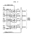
- FIG. 3 shows an example of the interconnection of channel elements in the transmit and receive directions.
- receive direction all the CSMs in a given chain receive the same information, i.e., the CSMs are connected using a broadcast bus rather than a daisy chain.
- Each of the channel elements in each of the chains receives baseband receive data for each of the three sectors ⁇ , ⁇ and ⁇ . Since the transmit and receive channels are symmetric, the same carrier assigned for the transmit direction is also assigned for the receive direction.
- a significant problem with the conventional single-carrier/multi-sector channel pooling arrangements described in conjunction with FIGS. 1 , 2 and 3 above is that when any one of the channel elements in a given chain is assigned to a particular carrier, all the channel elements in that chain, or in this case the corresponding channel unit board, cannot be assigned to any other carriers in the system. Another problem with the conventional arrangements is that a failure of a single channel element in the chain can cause the entire chain to fail. A need therefore exists for a multi-carrier/multi-sector channel pooling arrangement that provides increased system flexibility and reliability relative to conventional single-carrier/multi-sector channel pooling.
- WO-A-99/18744 discloses a base transceiver station for a mobile communications system, which is divided into a plurality of functional units that enables the signal processing resources to be flexibly allocated and cost-effectively implemented in hardware.
- a flexible communications interface is created between the base transceiver station units which allows the signal processing resources within the units to be used more efficiently.
- the base transceiver station hardware is dimensioned to statistically distribute the signal processing resources among the different radio transmission services available. Consequently, the allocated base transceiver station hardware can be used more efficiently, which minimizes the overall size and weight of the base station
- US-A-5 768 268 discloses an open-architecture digital cellular base station readily adapted to support communication over a variety of air interface standards.
- the base station includes a wideband digital transceiver system having transmit and receive sections. Within the transmit section, an input line interface operates to couple a plurality of input information signals onto a time-division multiplexed (TDM) transmit bus.
- TDM time-division multiplexed
- a plurality of digital transmitter modules are coupled to the TDM transmit bus, each of the digital transmitter modules generating a set of digital baseband signals in response to a corresponding set of the plurality of input information signals.
- the set of digital information signals are applied to a wideband summation network disposed to sequentially add the set of digital information signals into a wideband data stream.
- a wideband transmitter then generates a wideband transmission waveform using the wideband data stream.
- the receive section includes a wideband receiver for: (i) receiving an incident composite signal, and (ii) generating a digital representation of the incident composite signal in the form of a wideband digital data stream applied to a wideband data bus.
- a plurality of digital receiver modules are coupled to the wideband data bus. Each digital receiver module functions to recover a set of digital output signals from the wideband digital data stream, as well as to multiplex the set of digital signals onto a TDM receive bus.
- An output line interface serves to distribute the digital output signals among a plurality of output signal lines.
- JP-A-10 023 497 discloses a cell containing a first base station with conventional transceivers and base station facilities, and the antenna of a second base station facility; the first base station facility is made up of a group of base stations facilities where the equipment is integrated, but the second base station is a conventional local base station.
- a transceiver may have unused capacity and a caller with a low priority may not be assigned to the transceiver even though there is still room. This is due to the fact that the capacity is being kept available for a caller with a higher priority, since the assignments are based on priority.
- Traffic monitors are used by portable telephone providers to manage the traffic in every cell, so traffic can be assigned to the transceiver, based on the provider with the highest volume or according to a prearranged priority scale.
- Patent Publication WO95/33350 a wireless communication system basestation making use of a wideband, multichannel digital transceiver having incorporated therein a time division multiplc-access (TDM) bus for providing digital samples of a plurality of wireless communication channels, wherein the TDM bus is used as a crossbar switch to permit dynamic allocation of modulator and demodulator signal processing resources.
- TDM time division multiplc-access
- the invention of WO95/33350 allows various air interface standards, even those having different channel bandwidths, to be serviced by the same bascstation, with automatic redistribution of signal processing resources, eliminating the need to reconfigure the basestation when the loading of different types of wireless signaling traffic changes.
- a wireless communication system base station includes a number of channel unit boards, each with multiple channel elements for providing signal processing operations.
- a given channel unit board includes a multiplexer which is operative to implement multi-carrier/multi-sector channel pooling by assigning a given one of the channel elements of that board to any one of the multiple carriers of the system.
- the multiplexer in the given channel board may be operative to connect the channel elements of that board to I/Q signal buses associated with different ones of the system carriers.
- the I/Q signal bus for each of the carriers is then combined on the given board with corresponding signal buses for the same carrier from other boards.
- the invention can thus be used to assign each of N channel elements of the given channel unit board to a particular one of up to N carriers of the system.
- the invention allows channel elements of a channel unit board to be pooled across all the available carriers in a given system configuration.
- the invention provides increased system reliability, since any failed channel element on a given channel unit board is simply not used, and does not otherwise affect the performance of that channel unit board.
- the invention allows base station equipment to be easily and efficiently upgraded or otherwise reconfigured to support changes in operating standards.
- the present invention will be illustrated below in conjunction with exemplary wireless communication systems. It should be understood, however, that the invention is not limited to use with any particular type of wireless system, but is instead more generally applicable to any wireless system in which it is desirable to provide more flexible channel pooling capabilities in system base stations, such that the base stations can more readily accommodate upgrades or other changes in system operating standards.
- the techniques are illustrated with reference to systems configured in accordance with IS-95 CDMA standards, it will be apparent to those skilled in the art that the techniques are also applicable to other wireless systems.
- FIG. 4 shows an illustrative embodiment of a channel unit board 200 with multi-carrier/multi-sector channel pooling in accordance with the invention.
- This embodiment includes N channel elements 202-1, 202-2, . . . 202-N, also denoted CSM1 through CSMN, and a multi-carrier/multi-sector multiplexer 204.
- a system clock is coupled to each of the channel elements and the multiplexer 204.
- the multiplexer 204 has inputs coupled to ⁇ , ⁇ and ⁇ sector outputs from each of the channel elements 202- j .
- Each of the ⁇ , ⁇ and ⁇ sector outputs in this embodiment includes I and Q signals for that sector.
- this embodiment uses three sectors, it should be understood that the invention can be applied to any number of sectors.
- the multiplexer 204 can couple the sector outputs from the N channel elements to any one of up to N different carrier I/Q buses.
- the connection of ⁇ , ⁇ and ⁇ sector outputs from each channel element 202- j to particular channel buses is determined by a multiplexer control signal applied to the multiplexer 204.
- the number N is used to designate the number of channel elements as well as the maximum number of different carriers, for simplicity of illustration, it should be understood that the number of channel elements and number of carriers need not be equal, and in practice typically will not be equal. More specifically, the number of carriers is generally less than the number of channel elements in a given implementation.
- the multiplexer control signal may be generated, e.g., by a control computer, such as control computer 102 of FIG. 1 , associated with the corresponding system base station.
- the multiplexer 204 is further operative to combine the I and Q signals from downstream channel unit boards with the locally generated I and Q data streams of the channel unit board 200 on a per carrier, per sector basis.
- Other input signals applied to the multiplexer 204 include a CSM-to-Mux clock and a Mux-to-Backplane clock.
- the system control computer will direct the multiplexer 204 to route the sector outputs of the selected channel element, e.g., CSM2, to the carrier 1 I/Q bus.
- the I and Q signals from this channel element are then combined with the I and Q signals of the same carrier from downstream channel unit boards.
- the multiplexer will first combine the sector outputs of the two channel elements, e.g., CSM2 and CSM3, and then combine them with the carrier 2 I/Q bus from downstream channel unit boards. If another channel then needs to be added to carrier 3, another available channel element is selected and assigned to carrier 3, by generation of an appropriate multiplexer control signal.
- appropriate control logic in the multiplexer 204 any desired number of carriers and sectors can be supported in the channel unit board 200.
- FIG. 5 illustrates in greater detail the manner in which the N channel elements 202- j of the channel unit board 200 are combined in the transmit direction.
- Each of the channel elements 202- j is coupled to one of the carrier I/Q buses as previously described.
- the carrier I/Q buses are then applied to each of N combiners 225- j which sum the channel element outputs for each of the channel elements assigned to each of the carriers.
- a local combiner control signal controls the combiners 225- j such that the combiners combine the appropriate channel element signals for each of the carrier I/Q buses.
- the output of each of the combiners 225- j represents a local carrier I/Q bus for a particular one of the carriers.
- Each of these local carrier I/Q buses is applied to a multi-carrier digital combiner 230.
- the multi-carrier digital combiner 230 also receives as an input an upstream I/Q bus 231 carrying corresponding signals from other channel unit boards, and combines the local carrier I/Q buses with the I/Q buses from the other channel boards to generate a system transmit I/Q bus.
- the transmit direction combining process illustrated in FIG. 5 thus combines multi-carrier I/Q buses from different channel unit boards by daisy chaining the data from channel unit board to channel unit board and performing a digital sum in each channel unit board.
- the elements 225- j and 230 may represent elements of the multi-carrier/multi-sector multiplexer 204 of FIG. 4 .
- FIGS. 6A and 6B illustrate in greater detail the manner in which the N channel elements 202- j of the channel unit board 200 are combined in the receive direction.
- a single broadcast bus per carrier is used to interface a set of radio boards 232 with M channel unit boards each supporting up to N channel elements in the multi-carrier/multi-sector channel pool.
- a base station 235 with the set of radio boards 232 and multiple channel unit boards 200-1, 200-2, . . ., 200-M, each channel unit board will interface to the same I/Q bus, as shown in FIG. 6A .
- the I/Q bus in such an arrangement is comprised of N carrier/sectors, i.e., the total number of carrier and sector combinations is N.
- a 36-wire I/Q bus can be configured to provide one bit for I and one bit for Q at a specified clock rate.
- an I/Q bus selector 240 in response to an I/Q routing control signal, connects the correct carrier/sector I/Q bus to the channel elements 202-1, 202-2, . . ., 202-N, as shown in FIG. 6B .
- clock rates and bus structures used in conjunction with the invention may vary in accordance with design preference, and many alternative arrangements are possible. Such arrangements will be readily apparent to those skilled in the art.
- the above-described multi-carrier/multi-sector channel pooling arrangement provides substantially improved flexibility relative to the conventional single-carrier/multi-sector approach.
- the channel pooling of the present invention allows any channel element to be assigned to any carrier sector in the system.
- the channel pooling of the present invention can allow all the channel elements of a given channel unit board to be assigned to a single carrier, or each channel element to be assigned to a different one of K carriers, where K ⁇ N, or any of a number of other combinations.
- the invention can thus allow a given base station design to support different wireless communication standards using the same base station hardware.
- the invention also protects the investments of base station equipment purchasers, by allowing existing equipment to be easily and efficiently upgraded to provide additional capacity, or to support changes in operating standards. Furthermore, the invention also provides increased reliability, since any failed channel element on a given channel unit board is simply not used, and does not otherwise affect the performance of that channel unit board.
Landscapes
- Engineering & Computer Science (AREA)
- Computer Networks & Wireless Communication (AREA)
- Signal Processing (AREA)
- Mobile Radio Communication Systems (AREA)
- Digital Transmission Methods That Use Modulated Carrier Waves (AREA)
- Arrangements For Transmission Of Measured Signals (AREA)
- Near-Field Transmission Systems (AREA)
Applications Claiming Priority (2)
| Application Number | Priority Date | Filing Date | Title |
|---|---|---|---|
| US420275 | 1999-10-18 | ||
| US09/420,275 US7161912B1 (en) | 1999-10-18 | 1999-10-18 | Multi-carrier/multi-sector channel pooling in a wireless communication system base station |
Publications (3)
| Publication Number | Publication Date |
|---|---|
| EP1094676A2 EP1094676A2 (en) | 2001-04-25 |
| EP1094676A3 EP1094676A3 (en) | 2002-08-28 |
| EP1094676B1 true EP1094676B1 (en) | 2008-05-28 |
Family
ID=23665811
Family Applications (1)
| Application Number | Title | Priority Date | Filing Date |
|---|---|---|---|
| EP00308863A Expired - Lifetime EP1094676B1 (en) | 1999-10-18 | 2000-10-09 | Multi-carrier/multi-sector channel pooling in a wireless communication system base station |
Country Status (11)
| Country | Link |
|---|---|
| US (1) | US7161912B1 (enExample) |
| EP (1) | EP1094676B1 (enExample) |
| JP (1) | JP4625171B2 (enExample) |
| KR (1) | KR20010051057A (enExample) |
| CN (1) | CN1293500A (enExample) |
| AT (1) | ATE397358T1 (enExample) |
| AU (1) | AU6649600A (enExample) |
| BR (1) | BR0006679A (enExample) |
| CA (1) | CA2323375A1 (enExample) |
| DE (1) | DE60039015D1 (enExample) |
| ID (1) | ID27635A (enExample) |
Families Citing this family (5)
| Publication number | Priority date | Publication date | Assignee | Title |
|---|---|---|---|---|
| US6144646A (en) * | 1999-06-30 | 2000-11-07 | Motorola, Inc. | Method and apparatus for allocating channel element resources in communication systems |
| US8547909B1 (en) * | 2004-02-27 | 2013-10-01 | Sprint Spectrum L.P. | Method and system for dynamic assignment of overhead channel group |
| US9119092B1 (en) | 2008-05-06 | 2015-08-25 | Sprint Spectrum L.P. | Performance based selection of channel elements for use in a wireless network |
| CN101626619B (zh) * | 2009-08-04 | 2011-07-20 | 中国联合网络通信集团有限公司 | 一种移动通信设备的ce配置方法及其系统 |
| US20140146797A1 (en) | 2012-11-26 | 2014-05-29 | Adc Telecommunications, Inc. | Timeslot mapping and/or aggregation element for digital radio frequency transport architecture |
Citations (1)
| Publication number | Priority date | Publication date | Assignee | Title |
|---|---|---|---|---|
| WO1995033350A1 (en) * | 1994-06-01 | 1995-12-07 | Airnet Communications Corp. | Wideband wireless basestation making use of time division multiple-access bus to effect switchable connections to modulator/demodulator resources |
Family Cites Families (11)
| Publication number | Priority date | Publication date | Assignee | Title |
|---|---|---|---|---|
| US5021801A (en) | 1989-09-05 | 1991-06-04 | Motorola, Inc. | Antenna switching system |
| US5515378A (en) * | 1991-12-12 | 1996-05-07 | Arraycomm, Inc. | Spatial division multiple access wireless communication systems |
| FI105515B (fi) * | 1995-05-24 | 2000-08-31 | Nokia Networks Oy | Menetelmä kanavanvaihdon nopeuttamiseksi sekä solukkoradiojärjestelmä |
| US5768268A (en) | 1995-07-19 | 1998-06-16 | Watkins Johnson Company | Wideband base station architecture for digital cellular communications system |
| US5867763A (en) * | 1996-02-08 | 1999-02-02 | Qualcomm Incorporated | Method and apparatus for integration of a wireless communication system with a cable T.V. system |
| FI960987A7 (fi) * | 1996-03-01 | 1997-09-02 | Nokia Corp | Menetelmä tukiaseman ohjaamiseksi ja tukiasema |
| JPH1023497A (ja) | 1996-06-13 | 1998-01-23 | At & T Corp | 集中基地局を利用したセルラ無線電話システム |
| US6400966B1 (en) * | 1997-10-07 | 2002-06-04 | Telefonaktie Bolaget Lm Ericsson (Publ) | Base station architecture for a mobile communications system |
| US6006111A (en) * | 1997-10-08 | 1999-12-21 | Nortel Networks Corporation | Self-balancing matrix amplifier |
| DE69831240T2 (de) | 1998-10-15 | 2006-06-01 | Lucent Technologies Inc. | Rekonfigurierbares faseroptisches Netzwerk für Drahtlose Übertragung |
| US6587448B1 (en) * | 1999-10-18 | 2003-07-01 | Lucent Technologies Inc. | Reconfigurable wireless system base station |
-
1999
- 1999-10-18 US US09/420,275 patent/US7161912B1/en not_active Expired - Lifetime
-
2000
- 2000-10-09 DE DE60039015T patent/DE60039015D1/de not_active Expired - Lifetime
- 2000-10-09 EP EP00308863A patent/EP1094676B1/en not_active Expired - Lifetime
- 2000-10-09 AT AT00308863T patent/ATE397358T1/de not_active IP Right Cessation
- 2000-10-11 BR BR0006679-6A patent/BR0006679A/pt not_active Application Discontinuation
- 2000-10-12 CA CA002323375A patent/CA2323375A1/en not_active Abandoned
- 2000-10-13 AU AU66496/00A patent/AU6649600A/en not_active Abandoned
- 2000-10-17 CN CN00125997.0A patent/CN1293500A/zh active Pending
- 2000-10-17 ID IDP20000897A patent/ID27635A/id unknown
- 2000-10-17 KR KR1020000060877A patent/KR20010051057A/ko not_active Withdrawn
- 2000-10-18 JP JP2000317403A patent/JP4625171B2/ja not_active Expired - Fee Related
Patent Citations (1)
| Publication number | Priority date | Publication date | Assignee | Title |
|---|---|---|---|---|
| WO1995033350A1 (en) * | 1994-06-01 | 1995-12-07 | Airnet Communications Corp. | Wideband wireless basestation making use of time division multiple-access bus to effect switchable connections to modulator/demodulator resources |
Also Published As
| Publication number | Publication date |
|---|---|
| KR20010051057A (ko) | 2001-06-25 |
| AU6649600A (en) | 2001-04-26 |
| CN1293500A (zh) | 2001-05-02 |
| EP1094676A3 (en) | 2002-08-28 |
| ID27635A (id) | 2001-04-19 |
| JP4625171B2 (ja) | 2011-02-02 |
| CA2323375A1 (en) | 2001-04-18 |
| US7161912B1 (en) | 2007-01-09 |
| JP2001186553A (ja) | 2001-07-06 |
| DE60039015D1 (de) | 2008-07-10 |
| ATE397358T1 (de) | 2008-06-15 |
| BR0006679A (pt) | 2001-06-19 |
| EP1094676A2 (en) | 2001-04-25 |
Similar Documents
| Publication | Publication Date | Title |
|---|---|---|
| US6587448B1 (en) | Reconfigurable wireless system base station | |
| US6055230A (en) | Embedded digital beam switching | |
| US6539209B1 (en) | Code-division, multiple-access base station having transmit diversity | |
| AU678124B2 (en) | Multi-channel digital transceiver and method | |
| US6173177B1 (en) | Cellular base station with intelligent call routing | |
| AU753670B2 (en) | Base station architecture for a mobile communications system | |
| US6161024A (en) | Redundant broadband multi-carrier base station for wireless communications using omni-directional overlay on a tri-sectored wireless system | |
| EP0652644B1 (en) | Base station transmission-reception apparatus for cellular system | |
| US6134229A (en) | Multichannel broadband transceiver system making use of a distributed control architecture for digital signal processor array | |
| US6052365A (en) | Multi-channel digital data transmission in a wireless telecommunications system | |
| US6512755B1 (en) | Wireless telecommunications access system | |
| EP1094676B1 (en) | Multi-carrier/multi-sector channel pooling in a wireless communication system base station | |
| AU2008346632A1 (en) | Communication system, communication interface and communication method | |
| US6968183B2 (en) | Determining a multi-module dependent parameter at a telecommunication node | |
| GB2301755A (en) | Multiline wireless transmission in a wireless telecommunications system | |
| KR20020093553A (ko) | 다중 섹터 처리형 채널 카드 |
Legal Events
| Date | Code | Title | Description |
|---|---|---|---|
| PUAI | Public reference made under article 153(3) epc to a published international application that has entered the european phase |
Free format text: ORIGINAL CODE: 0009012 |
|
| AK | Designated contracting states |
Kind code of ref document: A2 Designated state(s): AT BE CH CY DE DK ES FI FR GB GR IE IT LI LU MC NL PT SE |
|
| AX | Request for extension of the european patent |
Free format text: AL;LT;LV;MK;RO;SI |
|
| PUAL | Search report despatched |
Free format text: ORIGINAL CODE: 0009013 |
|
| AK | Designated contracting states |
Kind code of ref document: A3 Designated state(s): AT BE CH CY DE DK ES FI FR GB GR IE IT LI LU MC NL PT SE |
|
| AX | Request for extension of the european patent |
Free format text: AL;LT;LV;MK;RO;SI |
|
| 17P | Request for examination filed |
Effective date: 20030215 |
|
| 17Q | First examination report despatched |
Effective date: 20030314 |
|
| AKX | Designation fees paid |
Designated state(s): AT BE CH CY DE DK ES FI FR GB GR IE IT LI LU MC NL PT SE |
|
| APBN | Date of receipt of notice of appeal recorded |
Free format text: ORIGINAL CODE: EPIDOSNNOA2E |
|
| APBR | Date of receipt of statement of grounds of appeal recorded |
Free format text: ORIGINAL CODE: EPIDOSNNOA3E |
|
| APBV | Interlocutory revision of appeal recorded |
Free format text: ORIGINAL CODE: EPIDOSNIRAPE |
|
| GRAP | Despatch of communication of intention to grant a patent |
Free format text: ORIGINAL CODE: EPIDOSNIGR1 |
|
| GRAS | Grant fee paid |
Free format text: ORIGINAL CODE: EPIDOSNIGR3 |
|
| GRAA | (expected) grant |
Free format text: ORIGINAL CODE: 0009210 |
|
| AK | Designated contracting states |
Kind code of ref document: B1 Designated state(s): AT BE CH CY DE DK ES FI FR GB GR IE IT LI LU MC NL PT SE |
|
| REG | Reference to a national code |
Ref country code: GB Ref legal event code: FG4D |
|
| REG | Reference to a national code |
Ref country code: CH Ref legal event code: EP |
|
| REF | Corresponds to: |
Ref document number: 60039015 Country of ref document: DE Date of ref document: 20080710 Kind code of ref document: P |
|
| REG | Reference to a national code |
Ref country code: IE Ref legal event code: FG4D |
|
| PG25 | Lapsed in a contracting state [announced via postgrant information from national office to epo] |
Ref country code: FI Free format text: LAPSE BECAUSE OF FAILURE TO SUBMIT A TRANSLATION OF THE DESCRIPTION OR TO PAY THE FEE WITHIN THE PRESCRIBED TIME-LIMIT Effective date: 20080528 Ref country code: ES Free format text: LAPSE BECAUSE OF FAILURE TO SUBMIT A TRANSLATION OF THE DESCRIPTION OR TO PAY THE FEE WITHIN THE PRESCRIBED TIME-LIMIT Effective date: 20080908 |
|
| PG25 | Lapsed in a contracting state [announced via postgrant information from national office to epo] |
Ref country code: AT Free format text: LAPSE BECAUSE OF FAILURE TO SUBMIT A TRANSLATION OF THE DESCRIPTION OR TO PAY THE FEE WITHIN THE PRESCRIBED TIME-LIMIT Effective date: 20080528 Ref country code: NL Free format text: LAPSE BECAUSE OF FAILURE TO SUBMIT A TRANSLATION OF THE DESCRIPTION OR TO PAY THE FEE WITHIN THE PRESCRIBED TIME-LIMIT Effective date: 20080528 |
|
| NLV1 | Nl: lapsed or annulled due to failure to fulfill the requirements of art. 29p and 29m of the patents act | ||
| PG25 | Lapsed in a contracting state [announced via postgrant information from national office to epo] |
Ref country code: SE Free format text: LAPSE BECAUSE OF FAILURE TO SUBMIT A TRANSLATION OF THE DESCRIPTION OR TO PAY THE FEE WITHIN THE PRESCRIBED TIME-LIMIT Effective date: 20080828 Ref country code: DK Free format text: LAPSE BECAUSE OF FAILURE TO SUBMIT A TRANSLATION OF THE DESCRIPTION OR TO PAY THE FEE WITHIN THE PRESCRIBED TIME-LIMIT Effective date: 20080528 Ref country code: PT Free format text: LAPSE BECAUSE OF FAILURE TO SUBMIT A TRANSLATION OF THE DESCRIPTION OR TO PAY THE FEE WITHIN THE PRESCRIBED TIME-LIMIT Effective date: 20081028 |
|
| PG25 | Lapsed in a contracting state [announced via postgrant information from national office to epo] |
Ref country code: BE Free format text: LAPSE BECAUSE OF FAILURE TO SUBMIT A TRANSLATION OF THE DESCRIPTION OR TO PAY THE FEE WITHIN THE PRESCRIBED TIME-LIMIT Effective date: 20080528 |
|
| PLBE | No opposition filed within time limit |
Free format text: ORIGINAL CODE: 0009261 |
|
| STAA | Information on the status of an ep patent application or granted ep patent |
Free format text: STATUS: NO OPPOSITION FILED WITHIN TIME LIMIT |
|
| 26N | No opposition filed |
Effective date: 20090303 |
|
| PG25 | Lapsed in a contracting state [announced via postgrant information from national office to epo] |
Ref country code: MC Free format text: LAPSE BECAUSE OF NON-PAYMENT OF DUE FEES Effective date: 20081031 |
|
| REG | Reference to a national code |
Ref country code: CH Ref legal event code: PL |
|
| PG25 | Lapsed in a contracting state [announced via postgrant information from national office to epo] |
Ref country code: IT Free format text: LAPSE BECAUSE OF FAILURE TO SUBMIT A TRANSLATION OF THE DESCRIPTION OR TO PAY THE FEE WITHIN THE PRESCRIBED TIME-LIMIT Effective date: 20080528 |
|
| PG25 | Lapsed in a contracting state [announced via postgrant information from national office to epo] |
Ref country code: IE Free format text: LAPSE BECAUSE OF NON-PAYMENT OF DUE FEES Effective date: 20081009 Ref country code: CH Free format text: LAPSE BECAUSE OF NON-PAYMENT OF DUE FEES Effective date: 20081031 Ref country code: LI Free format text: LAPSE BECAUSE OF NON-PAYMENT OF DUE FEES Effective date: 20081031 |
|
| PG25 | Lapsed in a contracting state [announced via postgrant information from national office to epo] |
Ref country code: LU Free format text: LAPSE BECAUSE OF NON-PAYMENT OF DUE FEES Effective date: 20081009 |
|
| PG25 | Lapsed in a contracting state [announced via postgrant information from national office to epo] |
Ref country code: CY Free format text: LAPSE BECAUSE OF FAILURE TO SUBMIT A TRANSLATION OF THE DESCRIPTION OR TO PAY THE FEE WITHIN THE PRESCRIBED TIME-LIMIT Effective date: 20080528 |
|
| PG25 | Lapsed in a contracting state [announced via postgrant information from national office to epo] |
Ref country code: GR Free format text: LAPSE BECAUSE OF FAILURE TO SUBMIT A TRANSLATION OF THE DESCRIPTION OR TO PAY THE FEE WITHIN THE PRESCRIBED TIME-LIMIT Effective date: 20080829 |
|
| REG | Reference to a national code |
Ref country code: GB Ref legal event code: 732E Free format text: REGISTERED BETWEEN 20131121 AND 20131127 |
|
| REG | Reference to a national code |
Ref country code: FR Ref legal event code: CD Owner name: ALCATEL-LUCENT USA INC. Effective date: 20131122 |
|
| REG | Reference to a national code |
Ref country code: FR Ref legal event code: GC Effective date: 20140410 |
|
| REG | Reference to a national code |
Ref country code: FR Ref legal event code: RG Effective date: 20141015 |
|
| REG | Reference to a national code |
Ref country code: FR Ref legal event code: PLFP Year of fee payment: 16 |
|
| REG | Reference to a national code |
Ref country code: FR Ref legal event code: PLFP Year of fee payment: 17 |
|
| PGFP | Annual fee paid to national office [announced via postgrant information from national office to epo] |
Ref country code: DE Payment date: 20161020 Year of fee payment: 17 Ref country code: GB Payment date: 20161020 Year of fee payment: 17 Ref country code: FR Payment date: 20161020 Year of fee payment: 17 |
|
| REG | Reference to a national code |
Ref country code: DE Ref legal event code: R119 Ref document number: 60039015 Country of ref document: DE |
|
| GBPC | Gb: european patent ceased through non-payment of renewal fee |
Effective date: 20171009 |
|
| REG | Reference to a national code |
Ref country code: FR Ref legal event code: ST Effective date: 20180629 |
|
| PG25 | Lapsed in a contracting state [announced via postgrant information from national office to epo] |
Ref country code: GB Free format text: LAPSE BECAUSE OF NON-PAYMENT OF DUE FEES Effective date: 20171009 Ref country code: DE Free format text: LAPSE BECAUSE OF NON-PAYMENT OF DUE FEES Effective date: 20180501 |
|
| PG25 | Lapsed in a contracting state [announced via postgrant information from national office to epo] |
Ref country code: FR Free format text: LAPSE BECAUSE OF NON-PAYMENT OF DUE FEES Effective date: 20171031 |
|
| REG | Reference to a national code |
Ref country code: DE Ref legal event code: R082 Ref document number: 60039015 Country of ref document: DE Representative=s name: BARKHOFF REIMANN VOSSIUS, DE Ref country code: DE Ref legal event code: R081 Ref document number: 60039015 Country of ref document: DE Owner name: WSOU INVESTMENTS, LLC, LOS ANGELES, US Free format text: FORMER OWNER: LUCENT TECHNOLOGIES INC., MURRAY HILL, N.J., US |