EP1094584A2 - Kabelhaltevorrichtung - Google Patents
Kabelhaltevorrichtung Download PDFInfo
- Publication number
- EP1094584A2 EP1094584A2 EP00119745A EP00119745A EP1094584A2 EP 1094584 A2 EP1094584 A2 EP 1094584A2 EP 00119745 A EP00119745 A EP 00119745A EP 00119745 A EP00119745 A EP 00119745A EP 1094584 A2 EP1094584 A2 EP 1094584A2
- Authority
- EP
- European Patent Office
- Prior art keywords
- cable
- holding device
- holding
- fluid supply
- cable holding
- Prior art date
- Legal status (The legal status is an assumption and is not a legal conclusion. Google has not performed a legal analysis and makes no representation as to the accuracy of the status listed.)
- Withdrawn
Links
- XEEYBQQBJWHFJM-UHFFFAOYSA-N Iron Chemical compound [Fe] XEEYBQQBJWHFJM-UHFFFAOYSA-N 0.000 claims abstract description 47
- 239000012530 fluid Substances 0.000 claims abstract description 39
- 229910052742 iron Inorganic materials 0.000 claims abstract description 23
- XLYOFNOQVPJJNP-UHFFFAOYSA-N water Substances O XLYOFNOQVPJJNP-UHFFFAOYSA-N 0.000 claims abstract description 4
- 238000001746 injection moulding Methods 0.000 claims description 4
- 239000013013 elastic material Substances 0.000 claims description 2
- 238000010409 ironing Methods 0.000 abstract description 20
- 238000004519 manufacturing process Methods 0.000 description 6
- 238000003780 insertion Methods 0.000 description 3
- 230000037431 insertion Effects 0.000 description 3
- 239000000463 material Substances 0.000 description 3
- 238000005516 engineering process Methods 0.000 description 2
- 230000001154 acute effect Effects 0.000 description 1
- 235000000396 iron Nutrition 0.000 description 1
- 238000000926 separation method Methods 0.000 description 1
Images
Classifications
-
- H—ELECTRICITY
- H02—GENERATION; CONVERSION OR DISTRIBUTION OF ELECTRIC POWER
- H02G—INSTALLATION OF ELECTRIC CABLES OR LINES, OR OF COMBINED OPTICAL AND ELECTRIC CABLES OR LINES
- H02G11/00—Arrangements of electric cables or lines between relatively-movable parts
- H02G11/003—Arrangements of electric cables or lines between relatively-movable parts using gravity-loaded or spring-loaded loop
-
- D—TEXTILES; PAPER
- D06—TREATMENT OF TEXTILES OR THE LIKE; LAUNDERING; FLEXIBLE MATERIALS NOT OTHERWISE PROVIDED FOR
- D06F—LAUNDERING, DRYING, IRONING, PRESSING OR FOLDING TEXTILE ARTICLES
- D06F81/00—Ironing boards
- D06F81/003—Ironing boards with flat iron support
Definitions
- the invention relates to a cable holding device for an electric cable of an iron with a holding fixture for the power cable, the cable holding device can be positioned with respect to a bracket support.
- Such cable holders are from the EP 0 278 097 B1 and DE 90 17 364 U1 are known.
- the object of the invention is such a holding device to create which can be used universally and especially a free movement of an iron in the Ironing area allowed.
- This task is the cable holder initially mentioned type solved by the invention another holding receptacle for a fluid supply hose for supplying water or steam to the iron.
- the cable holding device according to the invention can be held in place also use with steam irons, over a fluid supply hose with water or Steam are supplied. This is with a single Cable holder of the bracket area from both Power cable as well as from the fluid supply hose keepable.
- the holding fixture for the power cable and the further holder for the fluid supply hose substantially parallel are arranged to each other.
- the cable holding device in a simple manner and on the other hand, the insertion of power cables and fluid supply hose in the provided Carry out stop recordings in a simple way.
- the holding receptacle for the power cable and the further holding receptacle for the fluid supply hose essentially the same cross section on. This allows the cable holder to open easy to manufacture because there are no different Cross sections of the holding fixture are taken into account have to. Secondly, a user does not have to pay attention to which cable it is in which holder has to introduce, since both stop shots have equal rights are and a specific holding device Pick up power cord or fluid supply hose can.
- the cable holding device is designed as a clamping device.
- the lines (power cable and fluid supply hose) in the cable holder automatically held by clamping force without, for example a positive connection between Cable holder parts must be manufactured. This enables quick deployment and the cables can be easily removed accordingly remove the cable holding device according to the invention.
- the cable holding device a first clamp and one includes second clamp, between which the holding receptacles are formed. Between the clamps then the power cable and the fluid supply hose pinch, using the two clamps exert a clamping force on the cables that the Lines stops. By relative movement of the the cables can be taken from both clamps.
- a Clamping bracket has a recess to form the holding receptacle for the power cable and another recess to form the further holding receptacle for the fluid supply hose includes. Leave such clamps for example in a simple manner by means of a Manufacture injection molding process.
- clamping bracket are arranged and designed such that they are relative are so far movable to each other that the power cable and the fluid supply hose into the corresponding ones Hold receptacles can be inserted or removed from there are. This allows a cable can be inserted or removed via its long side and especially not by means of a cable end in the Stop recordings must be introduced.
- the relative mobility of the two clamps by appropriate storage these two clamps can be reached.
- Manufacturing technology particularly cheap and especially particularly It is inexpensive, however, if the clamping bracket is off are made of an elastic material. Through the Elasticity of the material can be the required Achieve mobility, so that on the one hand the power cable and the fluid supply hose is clampingly stable are and on the other hand in a simple manner in the cable holder insertable or removable from this are.
- the cable holder on an introducer for the power cable or for the fluid supply hose funnel-shaped facing the holding fixtures educated.
- the clamps By exercising accordingly Traction on a longitudinal side of the line towards the clamps to let the clamps so move relative to each other, i.e. deform elastically, that the corresponding line in the holding fixture arrives and is held there clamped.
- a holding fixture is essentially parallel is arranged to a clamp bracket level. This leaves over the scope of a holding fixture a line (power cable and / or fluid supply hose) evenly apply a clamping force.
- the holding device is formed in one piece. You can then manufacture in a simple and inexpensive manner and is easy to use and not very sensitive against wear. In particular, the entire cable holding device according to the invention then by means of an injection molding process and thus inexpensive to produce in large quantities.
- the cable holding device in simple Way to connect with a handrail which is held on an ironing board, for example conveniently, has a recess to put on the handrail. She leaves then with appropriate adjustment of the recess and an introducer of the handrail on simple Way on this one. In particular, thereby also replace cable holding devices and for example the cable holding device according to the invention use with existing ironing stations.
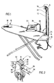
- a cable holding device which in Fig. 1 as a whole is designated 10, sits in the embodiment shown on a support rod 12, which means a bracket 14 connected to an ironing board 16 is.
- This ironing board 16 comprises an ironing board 18 and a shelf 20 for an iron 22, in which Embodiment shown, the bracket 14 with this Tray 20 is connected.
- the bracket 14 and the Handrail 12 are preferably via a pivot bearing 24 connected by means of which the handrail 12 pivot in the direction of the bracket 18 allows to keep the ironing board 16 space-saving can.
- the cable holding device for example, is attached to a wall (in the drawing not shown).
- the iron 22 is a steam iron, which over a power cable 26 is supplied with electrical power and a via a fluid supply line 28 Fluid for steam ironing is supplied. With the fluid is steam in particular, which in one pressure tank not shown in the drawing becomes.
- This pressure vessel can be arranged on the ironing table 16 be, in particular below the shelf 20 or outside the ironing board 16.
- the power cable 26 is on its end not shown in Fig. 1 with a plug Mistake. It can be provided that on the ironing board 16 and in particular on the shelf 20 an outlet arranged to power the iron 22 is.
- Both the power cable 26 and the fluid supply cable 28 are due to the cable holding device according to the invention 10 out, which on the support rod 12 in a vertical distance to the bracket 18 outside and in particular positioned above the temple area is.
- a portion of the power cable 26 as well as the length a section of the fluid supply line between the iron 22 and the cable holder 10 can on the one hand achieve that the iron 22 is free is movable in the temple area without, for example the power cable 26 or the fluid supply hose 28 dragged on the floor during the movement of the iron 22 and on the other hand the iron 22 in entire bracket area on the bracket 18 free is mobile.
- the support rod 12 is also arranged or formed so elastically that they to a certain extent when train gives way to the range of motion to enlarge the iron 22. That through the Cable holder 10 guided power cable 26 and the Fluid supply hose 28 can, for example, via one or more holding clips 30 on the holding rod 12 are kept, so that this is not easy from the Hang cable holder 10 down, but on the Handrail 12 are guided down. It can too several holding clips 30 can be provided and in particular each holding clips for the power cable 26 and the Fluid supply hose 28.
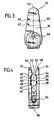
- the cable holding device is, as shown in Fig. 2, as a clamping device with a first clamping bracket 32 and an opposite second clamping bracket 34 is formed.
- the two clamps 32 and 34 have the shown embodiment in each case essentially plane opposite outer surfaces 36 and 38.
- the Outer surface 36 of the first clamp bracket 32 and the outer surface 38 of the second clamping bracket 34 are essentially parallel to each other.
- the clamps 32, 34 have the shape of an elongated triangle with rounded ones Tips (Fig. 3).
- first clamp 32 and the second Clamp 34 Between the first clamp 32 and the second Clamp 34 is a holding receptacle 40 for the power cable 26, in which this between the two clamps 32 and 34 can be clamped, and another Holding receptacle 40 for the fluid supply hose 28 formed, in which this can be clamped.
- this includes an inner surface 44 of the first clamp bracket 32, i.e. a surface facing the second clamping bracket 34 arcuate recess 46 to form the holding receptacle 40 for the power cable 26 and at a distance this recess 46 arranged another arcuate Recess 48, by means of which the further Holding receptacle 42 for the fluid supply hose 28 is formed.
- first clamp 32 In the first clamp 32 is between the two recesses 46 and 48 a web 50 for separation of the two holding receptacles 40 and 42 perpendicular to one Axis 52 (FIG. 3, FIG. 4) of the cable holding device 10 arranged.
- the second clamping bracket 34 has the recesses 46 and 48 corresponding recesses 54 and 56, which the mentioned recesses 46 and 48 in the first clamp 32 face each other.
- the holding receptacle 40 and the further holding receptacle 42 are essentially parallel to each other and essentially perpendicular to the axis 52 of the cable holding device 10 (Fig. 3) and substantially parallel to the outer surfaces 36, 38 of the two clamps 32 and 34 oriented.
- the first clamping bracket is on an introducer 58 (FIG. 4) 32 and the second clamping bracket 34 beveled in such a way that the introducer 58 is funnel-shaped is with a "funnel opening" 60 which the facing two holding receptacles 40 and 42.
- the introducer 58 trained such that they have a has an acute angle to the axis 52 (FIG. 4).
- the recess follows on the first clamping bracket 32 46 and on the second clamping bracket 34 the recess 54 to form the holding receptacle 40.
- the first clamp 32 and the second clamp 34 sit on a support body 64 such that between the A corresponding distance is formed inside surfaces 44 to provide the holding receptacles 40 and 42.
- the two clamps 32 and 34 are in one piece formed with the holding body 64. This includes the cable holding device 10 according to the invention essentially only one component.
- a recess 66 is formed in the holding body 64, by means of which the cable holding device 10 on the Holding rod 12 can be placed and in particular in which insertable the corresponding end of the support rod 12 is.
- This recess 66 and the end of the Handrail 12 can be coordinated so that the cable holder 10 on the support rod 12th can be positioned by means of a clamp seat. It can alternatively or additionally, it can be provided that a holding pin or a holding screw over a corresponding one Opening 68 in the first clamp 32 or the second clamping bracket 34 for fixing the cable holding device 10 is insertable on the support rod 12.
- the cable holding device 10 according to the invention can be in a simple way from a plastic material an injection molding process.
- the material with its elastic properties for the cable holding device 10 is selected such that the first clamp 32 and the second clamp 34 are so movable relative to each other that the Power cable 26 and the fluid supply hose 28 in the assigned holding receptacles 40 and 42 about the introducer 58 are insertable and there by means of the two clamps 32 and 34 exercised relative to each other Clamping force are maintained.
- the cable holding device 10 works as follows:
- the cable holder 10 as described above, at a vertical distance from an ironing board 18 positioned.
- the length of the fluid supply hose 28 becomes longer the introductory 58 introduced and in the further Holding receptacle 42 clamped.
- the power cord 26 will inserted and clamped in the holding receptacle 40.
- the End of the power cable 26 comes with a power supply connected, the end of the fluid supply hose 28th is with a fluid supply, such as a Steam generator connected.
Landscapes
- Engineering & Computer Science (AREA)
- Textile Engineering (AREA)
- Installation Of Indoor Wiring (AREA)
- Manufacturing Of Electrical Connectors (AREA)
Abstract
Description
Es zeigen:
- Fig. 1
- Eine perspektivische Ansicht eines Bügelbretts mit einem Bügeleisen und an dem Bügelbrett gehaltener erfindungsgemäßer Kabelhaltevorrichtung;
- Fig. 2
- eine vergrößerte perspektivische Ansicht der Kabelhaltevorrichtung gemäß Fig. 1 (dortiger Bereich A);
- Fig. 3
- eine vordere Draufsicht auf die Kabelhaltevorrichtung gemäß Fig. 2 und
- Fig. 4
- eine seitliche Draufsicht auf die Kabelhaltevorrichtung gemäß Fig. 2.
Claims (13)
- Kabelhaltevorrichtung für ein Stromkabel (26) eines Bügeleisens (22) mit einer Halteaufnahme (40) für das Stromkabel (26), wobei die Kabelhaltevorrichtung (10) bezüglich einer Bügelauflage (18) positionierbar ist,
gekennzeichnet durch eine weitere Halteaufnahme (42) für einen Fluidzuführungsschlauch (28) zur Zuführung von Wasser oder Dampf zum Bügeleisen (22). - Kabelhaltevorrichtung nach Anspruch 1, dadurch gekennzeichnet, daß die Halteaufnahme (40) für das Stromkabel (26) und die weitere Halteaufnahme (42) für den Fluidzuführungsschlauch (28) im wesentlichen parallel zueinander angeordnet sind.
- Kabelhaltevorrichtung nach Anspruch 1 oder 2, dadurch gekennzeichnet, daß die Halteaufnahme (40) für das Stromkabel (26) und die weitere Halteaufnahme (42) für den Fluidzuführungsschlauch (28) im wesentlichen den gleichen Querschnitt aufweisen.
- Kabelhaltevorrichtung nach einem der vorangehenden Ansprüche, dadurch gekennzeichnet, daß die Kabelhaltevorrichtung (10) als Klemmvorrichtung ausgebildet ist.
- Kabelhaltevorrichtung nach einem der vorangehenden Ansprüche, dadurch gekennzeichnet, daß die Kabelhaltevorrichtung (10) einen ersten Klemmbügel (32) und einen zweiten Klemmbügel (34) umfaßt, zwischen welchen die Halteaufnahmen (40, 42) gebildet sind.
- Kabelhaltevorrichtung nach Anspruch 5, dadurch gekennzeichnet, daß ein Klemmbügel (33; 34) eine Ausnehmung (46; 54) zur Bildung der Halteaufnahme (40) für das Stromkabel (26) und eine weitere Ausnehmung (48; 56) zur Bildung der weiteren Halteaufnahme (42) für den Fluidzuführungsschlauch (28) umfaßt.
- Kabelhaltevorrichtung nach Anspruch 5 oder 6, dadurch gekennzeichnet, daß die Klemmbügel (32, 34) derart angeordnet und ausgebildet sind, daß sie relativ zueinander so weit beweglich sind, daß das Stromkabel (26) und der Fluidzuführungsschlauch (28) in die entsprechenden Halteaufnahmen (40, 42) einführbar sind bzw. von dort herausnehmbar sind.
- Kabelhaltevorrichtung nach Anspruch 7, dadurch gekennzeichnet, daß die Klemmbügel (32, 34) aus einem elastischen Material gefertigt sind.
- Kabelhaltevorrichtung nach einem der vorangehenden Ansprüche, dadurch gekennzeichnet, daß die Kabelhaltevorrichtung (10) an einem Einführende (58) für das Stromkabel (26) bzw. für den Fluidzuführungsschlauch (28) den Halteaufnahmen (40; 42) zugewandt trichterförmig ausgebildet ist.
- Kabelhaltevorrichtung nach einem der Ansprüche 5 bis 9, dadurch gekennzeichnet, daß eine Halteaufnahme (40; 42) im wesentlichen parallel zu einer Klemmbügelebene (36, 38) angeordnet ist.
- Kabelhaltevorrichtung nach einem der vorangehenden Ansprüche, dadurch gekennzeichnet, daß die Kabelhaltevorrichtung einstückig ausgebildet ist.
- Kabelhaltevorrichtung nach einem der vorangehenden Ansprüche, dadurch gekennzeichnet, daß die Kabelhaltevorrichtung mittels eines Spritzgießverfahrens herstellbar ist.
- Kabelhaltevorrichtung nach einem der vorangehenden Ansprüche, gekennzeichnet durch eine Ausnehmung (66) zum Aufsetzen der Kabelhaltevorrichtung auf eine Haltestange (12).
Applications Claiming Priority (2)
| Application Number | Priority Date | Filing Date | Title |
|---|---|---|---|
| DE29918638U DE29918638U1 (de) | 1999-10-22 | 1999-10-22 | Kabelhaltevorrichtung |
| DE29918638U | 1999-10-22 |
Publications (2)
| Publication Number | Publication Date |
|---|---|
| EP1094584A2 true EP1094584A2 (de) | 2001-04-25 |
| EP1094584A3 EP1094584A3 (de) | 2002-01-16 |
Family
ID=8080637
Family Applications (1)
| Application Number | Title | Priority Date | Filing Date |
|---|---|---|---|
| EP00119745A Withdrawn EP1094584A3 (de) | 1999-10-22 | 2000-09-09 | Kabelhaltevorrichtung |
Country Status (2)
| Country | Link |
|---|---|
| EP (1) | EP1094584A3 (de) |
| DE (1) | DE29918638U1 (de) |
Cited By (1)
| Publication number | Priority date | Publication date | Assignee | Title |
|---|---|---|---|---|
| US7083447B2 (en) | 2004-02-16 | 2006-08-01 | Dspace Digital Signal Processing And Control Engineering Gmbh | Printed circuit board module and disconnect bow |
Families Citing this family (1)
| Publication number | Priority date | Publication date | Assignee | Title |
|---|---|---|---|---|
| USD514766S1 (en) * | 2001-05-14 | 2006-02-07 | Axana 2000 S.R.L. | Combined ironing board, electric iron, and iron holder |
Family Cites Families (5)
| Publication number | Priority date | Publication date | Assignee | Title |
|---|---|---|---|---|
| US2488255A (en) * | 1948-09-24 | 1949-11-15 | Martha C Allen | Cord holder for electric irons |
| GB660621A (en) * | 1949-05-30 | 1951-11-07 | Marcus James Henry Bruce | Improvements in supports for cables of electric irons |
| FR1045502A (fr) * | 1951-11-27 | 1953-11-26 | Support flexible pour cordon d'alimentation de fer à repasser électrique | |
| DE8700394U1 (de) * | 1987-01-09 | 1987-04-09 | Hailo-Werk Rudolf Loh Gmbh & Co Kg, 6342 Haiger | Schnurhalter für ein Bügeleisen |
| DE9017364U1 (de) | 1990-12-22 | 1992-01-23 | Hailo-Werk Rudolf Loh Gmbh & Co Kg, 6342 Haiger | Kabelklemme |
-
1999
- 1999-10-22 DE DE29918638U patent/DE29918638U1/de not_active Expired - Lifetime
-
2000
- 2000-09-09 EP EP00119745A patent/EP1094584A3/de not_active Withdrawn
Cited By (1)
| Publication number | Priority date | Publication date | Assignee | Title |
|---|---|---|---|---|
| US7083447B2 (en) | 2004-02-16 | 2006-08-01 | Dspace Digital Signal Processing And Control Engineering Gmbh | Printed circuit board module and disconnect bow |
Also Published As
| Publication number | Publication date |
|---|---|
| EP1094584A3 (de) | 2002-01-16 |
| DE29918638U1 (de) | 2000-03-09 |
Similar Documents
| Publication | Publication Date | Title |
|---|---|---|
| DE4434202B4 (de) | Kabeldurchführungsleiste | |
| CH667553A5 (de) | Schraubenlose elektrische klemme. | |
| DE3311362C1 (de) | Schleifleitungsanordnung | |
| DE19904087A1 (de) | Kupplungsstecker | |
| DE3001917C2 (de) | Fadenspleißvorrichtung | |
| DE3719984A1 (de) | Vorrichtung zur verbindung von schaltern mit den untersaetzen fuer buegeleisen | |
| DE3110298A1 (de) | "vorrichtung zum einklemmen eines kabels" | |
| EP1094584A2 (de) | Kabelhaltevorrichtung | |
| CH664144A5 (de) | Druckluft-fadenspleissvorrichtung. | |
| DE102011085793A1 (de) | Halterungsvorrichtung zum Haltern eines Kabels oder einer Leitung an einer Strukturkomponente eines Luft- oder Raumfahrzeugs sowie Luft- oder Raumfahrzeug | |
| DE69807982T2 (de) | Gerät zum Anbringen eines Leitungsdurchführungspfropfens | |
| DE3211259C2 (de) | Anordnung zum gespannten Verlegen einer Leitung od.dgl., vorzugsweise eines elektrischen Drahtes oder Kabels | |
| DE2750896C2 (de) | Halter für einen stabförmigen Gegenstand | |
| DE4037398A1 (de) | Halter, insbesondere kerzenhalter | |
| DE202016106541U1 (de) | Steuerkasten mit Kabelzugentlastung | |
| DE60013343T2 (de) | Steckverbindung eines Trägers in einer Öffnung , insbesondere eines Elektroventilträgers einer Geschirrspülmaschine | |
| AT380132B (de) | Tragvorrichtung zur aufnahme und fixierung von isolierten freileitungsleitern, kabeln od. dgl. | |
| DE19526446B4 (de) | Sammelhalter für Installationsleitungen | |
| DE8427926U1 (de) | Vorrichtung zum Aufhängen von Lampen | |
| DE3430904C2 (de) | ||
| EP0183065A2 (de) | Elektrische Schreibtischleuchte oder dergleichen | |
| DE60110958T2 (de) | Mehrfachleistungs-Steckverbinder mit hoher Packungsdichte | |
| DE2342829C3 (de) | Hängerklemme | |
| DE7825267U1 (de) | Auslaßdose für elektrische Leitungen zur paarweisen Anordnung an einer Wand | |
| DE4202492A1 (de) | Vorrichtung zum verschwenkbaren anbringen von einrichtungen |
Legal Events
| Date | Code | Title | Description |
|---|---|---|---|
| PUAI | Public reference made under article 153(3) epc to a published international application that has entered the european phase |
Free format text: ORIGINAL CODE: 0009012 |
|
| AK | Designated contracting states |
Kind code of ref document: A2 Designated state(s): AT BE CH CY DE DK ES FI FR GB GR IE IT LI LU MC NL PT SE |
|
| AX | Request for extension of the european patent |
Free format text: AL;LT;LV;MK;RO;SI |
|
| PUAL | Search report despatched |
Free format text: ORIGINAL CODE: 0009013 |
|
| AK | Designated contracting states |
Kind code of ref document: A3 Designated state(s): AT BE CH CY DE DK ES FI FR GB GR IE IT LI LU MC NL PT SE |
|
| AX | Request for extension of the european patent |
Free format text: AL;LT;LV;MK;RO;SI |
|
| 17P | Request for examination filed |
Effective date: 20020328 |
|
| AKX | Designation fees paid |
Free format text: AT BE CH CY DE DK ES FI FR GB GR IE IT LI LU MC NL PT SE |
|
| RAP1 | Party data changed (applicant data changed or rights of an application transferred) |
Owner name: ALFRED KAERCHER GMBH & CO. KG |
|
| STAA | Information on the status of an ep patent application or granted ep patent |
Free format text: STATUS: THE APPLICATION IS DEEMED TO BE WITHDRAWN |
|
| 18D | Application deemed to be withdrawn |
Effective date: 20070403 |