EP1094183A2 - Hinge device - Google Patents
Hinge device Download PDFInfo
- Publication number
- EP1094183A2 EP1094183A2 EP20000119543 EP00119543A EP1094183A2 EP 1094183 A2 EP1094183 A2 EP 1094183A2 EP 20000119543 EP20000119543 EP 20000119543 EP 00119543 A EP00119543 A EP 00119543A EP 1094183 A2 EP1094183 A2 EP 1094183A2
- Authority
- EP
- European Patent Office
- Prior art keywords
- hinge
- eccentric
- adjustment device
- frame
- door leaf
- Prior art date
- Legal status (The legal status is an assumption and is not a legal conclusion. Google has not performed a legal analysis and makes no representation as to the accuracy of the status listed.)
- Granted
Links
Images

Classifications
-
- E—FIXED CONSTRUCTIONS
- E05—LOCKS; KEYS; WINDOW OR DOOR FITTINGS; SAFES
- E05D—HINGES OR SUSPENSION DEVICES FOR DOORS, WINDOWS OR WINGS
- E05D7/00—Hinges or pivots of special construction
- E05D7/04—Hinges adjustable relative to the wing or the frame
- E05D7/0415—Hinges adjustable relative to the wing or the frame with adjusting drive means
-
- E—FIXED CONSTRUCTIONS
- E05—LOCKS; KEYS; WINDOW OR DOOR FITTINGS; SAFES
- E05D—HINGES OR SUSPENSION DEVICES FOR DOORS, WINDOWS OR WINGS
- E05D7/00—Hinges or pivots of special construction
- E05D7/10—Hinges or pivots of special construction to allow easy separation or connection of the parts at the hinge axis
- E05D7/1005—Hinges or pivots of special construction to allow easy separation or connection of the parts at the hinge axis by axially moving free pins, balls or sockets
- E05D2007/1027—Hinges or pivots of special construction to allow easy separation or connection of the parts at the hinge axis by axially moving free pins, balls or sockets by axially moving free pins
-
- E—FIXED CONSTRUCTIONS
- E05—LOCKS; KEYS; WINDOW OR DOOR FITTINGS; SAFES
- E05D—HINGES OR SUSPENSION DEVICES FOR DOORS, WINDOWS OR WINGS
- E05D7/00—Hinges or pivots of special construction
- E05D7/10—Hinges or pivots of special construction to allow easy separation or connection of the parts at the hinge axis
- E05D7/1005—Hinges or pivots of special construction to allow easy separation or connection of the parts at the hinge axis by axially moving free pins, balls or sockets
-
- E—FIXED CONSTRUCTIONS
- E05—LOCKS; KEYS; WINDOW OR DOOR FITTINGS; SAFES
- E05Y—INDEXING SCHEME RELATING TO HINGES OR OTHER SUSPENSION DEVICES FOR DOORS, WINDOWS OR WINGS AND DEVICES FOR MOVING WINGS INTO OPEN OR CLOSED POSITION, CHECKS FOR WINGS AND WING FITTINGS NOT OTHERWISE PROVIDED FOR, CONCERNED WITH THE FUNCTIONING OF THE WING
- E05Y2900/00—Application of doors, windows, wings or fittings thereof
- E05Y2900/10—Application of doors, windows, wings or fittings thereof for buildings or parts thereof
- E05Y2900/13—Application of doors, windows, wings or fittings thereof for buildings or parts thereof characterised by the type of wing
- E05Y2900/132—Doors
Definitions
- the invention relates to a hinge device for pivoting mounting of a door leaf on a frame, one Frame or the like, with at least two hinge straps, one of which one a height adjustment device for vertical adjustment of the door leaf in relation to the frame, the frame or the like. having.
- the aim is that a step-by-step adjustment of the vertical level of the door leaf is possible without fixing the door leaf required after each adjustment step should be.
- a known such height adjustment device is as Spindle gear designed. This is a comparatively complicated technical-constructive execution, the moreover significant constructive adjustments of the hinge strap as a whole.
- the invention has for its object a hinge device for pivoting storage of a door leaf on one Frame, a frame or the like. to create one hand with can be realized with little technical and constructive effort should and on the other hand it is ensured that a height adjustment of the door leaf in small adjustment steps without any clampings or fixations to be made in the meantime or the like. is possible.
- the Height adjustment device has an eccentric through which Rotation of a hinge flap on the door of the height adjustment device having hinge strap and thus the door leaf in the vertical direction with respect to the frame, the frame or the like. is adjustable. Through the eccentric a comparatively simple technical and constructive solution for the height adjustment of the door leaf in the corresponding Hinged tape created.
- Hinge device is the circumference of the eccentric disc Eccentric of the height adjustment device as a succession flattened sections formed.
- Hinge device has another one of the at least two Hinge straps a side adjustment device for horizontal Adjustment of the door leaf in relation to the frame and frame opening or the like. on, which is the height adjustment having hinge band in the horizontal direction and the hinge band having the side adjustment device are freely adjustable in the vertical direction.
- the side adjustment device also advantageously has one Eccentric on, by the rotation of a door wing side Hinge tab of the side adjustment device Hinged hinge and thus the door leaf in the horizontal direction or the like with respect to the frame, frame opening. adjustable is.
- the lateral adjustment device can move freely hinge band with a height adjustment of the window sash when one reaches the eccentric disc the eccentric of the side adjustment device receiving recess of the hinge flap on the door leaf of the hinge strap having the side adjustment device in the vertical direction larger than the diameter of the eccentric disc the eccentric of the side adjustment device.
- a hinge device is used for pivoting Storage of a door leaf on a frame, a frame or the like.
- hinge device The illustrated with reference to Figures 1 to 10 and below embodiment of the hinge device according to the invention explained in more detail consists of at least two hinge straps 1, 2, as shown in Figures 1 to 4 and 5 to 8 in different Views are shown.
- the hinge strap 1 and the hinge strap 2 are with their Pivot pins 3 and 4 arranged on the same pivot axis 5, so that the door wing, not shown in the figures about this pivot axis 5 pivotable on the frame, on the frame or the like. is stored.
- Any further hinge straps of the hinge device according to the invention are also on with their pivot bolts this pivot axis 5 arranged.
- the hinge strap 1 shown in Figures 1 to 4 is equipped with a height adjustment device 6.
- This height adjustment device 6 is used for vertical adjustment of the Position of the door leaf on the one to be closed or opening area of the frame, the frame, to be released by him or the like.
- the height adjustment device 6 has an eccentric 7 on.
- An eccentric 8 of this eccentric 7 is in one Recess 9 of a hinge flap 10 on the door leaf side is arranged.
- the dimension of the recess 9 in the hinge tab on the door leaf 10 in the vertical direction corresponds to the diameter the eccentric 8 of the eccentric 7 of the height adjustment device.
- the dimension of the recess 9 in the door leaf Hinge tab 10 in the horizontal direction is slightly larger than the diameter of the eccentric 8 of the eccentric 7 is achieved that any lateral adjustment of the Door leaf can be made without being in any Way on the function of the with the height adjustment 6th equipped hinge strap 1 would be affected.
- a rotation of the eccentric 7 is accomplished in that a corresponding tool in a trained in the eccentric 7 Hexagon 11 is inserted and rotated.
- Hinge device is also one in the figures 5 to 8 shown hinge strap 2 realized side adjustment 13 provided with an eccentric 14, which the above-mentioned eccentric 7 of the height adjustment device 6 corresponds.
- the eccentric 14 of the side adjustment device 13 an eccentric 15, which also the sequence has flattened sections 12.
- This eccentric disc 15 of the eccentric 14 of the side adjustment device is in a recess 16 one in the hinge band 2 included hinge flap 17 on the door leaf side added.
- the recess 16 of this wing side Hinge tab 17 has a dimension in the lateral direction, which is the diameter of the eccentric disc 15 of the eccentric 14 corresponds to the side adjustment device 13.
- One turn of the eccentric 14 has due to the eccentricity of the eccentric disc 15 thus the consequence that the hinge tab 17 and thus the door leaf in a lateral direction on the swivel axis 5 of the door leaf is moved to or away from this.
- This movement of the door leaf is possible because in the Figures 1 to 4 described hinge 1 the side Extension of the recess 9 of the hinge flap on the door leaf 10 is larger than the diameter of the eccentric disc 8 of the eccentric 7 of the height adjustment device 6.
- the flattened sections 12 of the eccentric disc 15 of the eccentric 14 of the side adjustment prevent unwanted lateral adjustments of the door leaf in relation to the frame, the frame or the like. when assembling the door because that required for lateral movement of the door leaf Torque is not sufficient due to the flattened Sections 12 to achieve overturning moment.
Abstract
Description
Die Erfindung bezieht sich auf eine Scharniereinrichtung zur schwenkbaren Lagerung eines Türflügels an einem Rahmen, einer Zarge od.dgl., mit zumindest zwei Scharnierbändern, von denen eines eine Höhenverstelleinrichtung zur vertikalen Verstellung des Türflügels in bezug auf den Rahmen, die Zarge od.dgl. aufweist.The invention relates to a hinge device for pivoting mounting of a door leaf on a frame, one Frame or the like, with at least two hinge straps, one of which one a height adjustment device for vertical adjustment of the door leaf in relation to the frame, the frame or the like. having.
Bei derartigen Scharniereinrichtungen wird angestrebt, daß eine in Schritten erfolgende Einstellung des Vertikalniveaus des Türflügels möglich ist, ohne daß eine Fixierung des Türflügels nach dem jeweils durchgeführten Anpassungsschritt erforderlich sein soll.With such hinge devices, the aim is that a step-by-step adjustment of the vertical level of the door leaf is possible without fixing the door leaf required after each adjustment step should be.
Eine bekannte derartige Höhenverstelleinrichtung ist als Spindelgetriebe ausgestaltet. Hierbei handelt es sich um eine vergleichsweise komplizierte technisch-konstruktive Ausführung, die darüber hinaus beträchtliche konstruktive Anpassungen des Scharnierbands insgesamt erfordert.A known such height adjustment device is as Spindle gear designed. This is a comparatively complicated technical-constructive execution, the moreover significant constructive adjustments of the hinge strap as a whole.
Der Erfindung liegt die Aufgabe zugrunde, eine Scharniereinrichtung zur schwenkbaren Lagerung eines Türflügels an einem Rahmen, einer Zarge od.dgl. zu schaffen, die einerseits mit geringem technisch-konstruktiven Aufwand realisierbar sein soll und bei der andererseits gewährleistet ist, daß eine Höhenverstellung des Türflügels in kleinen Anpassungsschritten ohne zwischenzeitlich vorzunehmende Klemmungen, Fixierungen od.dgl. möglich ist.The invention has for its object a hinge device for pivoting storage of a door leaf on one Frame, a frame or the like. to create one hand with can be realized with little technical and constructive effort should and on the other hand it is ensured that a height adjustment of the door leaf in small adjustment steps without any clampings or fixations to be made in the meantime or the like. is possible.
Diese Aufgabe wird erfindungsgemäß dadurch gelöst, daß die Höhenverstelleinrichtung einen Exzenter aufweist, durch dessen Drehung ein türflügelseitiger Scharnierlappen des die Höhenverstelleinrichtung aufweisenden Scharnierbands und damit der Türflügel in Vertikalrichtung in bezug auf den Rahmen, die Zarge od.dgl. verstellbar ist. Durch den Exzenter wird eine vergleichsweise einfache technisch-konstruktive Lösung für die Höhenverstellung des Türflügels in dem entsprechenden Scharnierband geschaffen.This object is achieved in that the Height adjustment device has an eccentric through which Rotation of a hinge flap on the door of the height adjustment device having hinge strap and thus the door leaf in the vertical direction with respect to the frame, the frame or the like. is adjustable. Through the eccentric a comparatively simple technical and constructive solution for the height adjustment of the door leaf in the corresponding Hinged tape created.
Um bei mit einem entsprechenden Eigengewicht versehenen Türflügeln zu verhindern, daß das aufgrund des Eigengewichts entstehende Drehmoment eine Vertikalverstellung des Türflügels bewirkt, ist es vorteilhaft, wenn der Exzenter der Höhenverstelleinrichtung am Umfang seiner Exzenterscheibe abgeflachte Abschnitte aufweist. Hierdurch wird ein zu überwindendes Kippmoment vorgegeben, durch das ein etwaig am Exzenter auftretendes Drehmoment neutralisiert wird. For doors with a corresponding weight to prevent that due to its own weight resulting torque a vertical adjustment of the door leaf causes it is advantageous if the eccentric of the height adjustment device flattened at the periphery of its eccentric disc Has sections. This will be a thing to be overcome Tilting moment given by the one at the eccentric occurring torque is neutralized.
Gemäß einer vorteilhaften Weiterbildung der erfindungsgemäßen Scharniereinrichtung ist der Umfang der Exzenterscheibe des Exzenters der Höhenverstelleinrichtung als Aufeinanderfolge abgeflachter Abschnitte ausgebildet.According to an advantageous development of the invention Hinge device is the circumference of the eccentric disc Eccentric of the height adjustment device as a succession flattened sections formed.
Bei einer vorteilhaften Weiterbildung der erfindungsgemäßen Scharniereinrichtung weist ein anderes der zumindest zwei Scharnierbänder eine Seitenverstelleinrichtung zur horizontalen Verstellung des Türflügels in bezug auf die Rahmen-, Zargenöffnung od.dgl. auf, wobei das die Höhenverstelleinrichtung aufweisende Scharnierband in horizontaler Richtung und das die Seitenverstelleinrichtung aufweisende Scharnierband in vertikaler Richtung frei verstellbar sind.In an advantageous development of the invention Hinge device has another one of the at least two Hinge straps a side adjustment device for horizontal Adjustment of the door leaf in relation to the frame and frame opening or the like. on, which is the height adjustment having hinge band in the horizontal direction and the hinge band having the side adjustment device are freely adjustable in the vertical direction.
Vorteilhaft weist die Seitenverstelleinrichtung ebenfalls einen Exzenter auf, durch dessen Drehung ein türflügelseitiger Scharnierlappen des die Seitenverstelleinrichtung aufweisenden Scharnierbands und damit der Türflügel in Horizontalrichtung in bezug auf die Rahmen-, Zargenöffnung od.dgl. verstellbar ist.The side adjustment device also advantageously has one Eccentric on, by the rotation of a door wing side Hinge tab of the side adjustment device Hinged hinge and thus the door leaf in the horizontal direction or the like with respect to the frame, frame opening. adjustable is.
Auch hierbei ist es zweckmäßig, wenn zur Selbsthemmung der Seitenverstelleinrichtung gegen ein etwaig auftretendes Drehmoment eine Exzenterscheibe des Exzenters der Seitenverstelleinrichtung an ihrem Umfang abgeflachte Abschnitte aufweist, wobei in vorteilhafter Weiterbildung der Umfang der Exzenterscheibe des Exzenters der Seitenverstelleinrichtung als Aufeinanderfolge abgeflachter Abschnitte ausgebildet ist.Again, it is useful if the self-locking Side adjustment device against any occurring Torque an eccentric disk of the eccentric of the side adjustment device has flattened sections on its circumference, in an advantageous further development, the scope of the Eccentric disc of the eccentric of the side adjustment device is designed as a succession of flattened sections.
Eine Freigängigkeit des die Höhenverstelleinrichtung aufweisenden Scharnierbands bei einer Seitenverstellung des Türflügels ist in technisch-konstruktiv wenig aufwendiger Weise erreichbar, wenn eine die Exzenterscheibe des Exzenters der Höhenverstelleinrichtung aufnehmende Ausnehmung des türflügelseitigen Scharnierlappens des die Höhenverstelleinrichtung aufweisenden Scharnierbands in horizontaler Richtung größer als der Durchmesser der Exzenterscheibe des Exzenters der Höhenverstelleinrichtung ist.Freedom of movement for the height adjustment device Hinged hinge with a side adjustment of the door leaf is technically and structurally inexpensive to achieve, if one the eccentric of the eccentric of the height adjustment device receiving recess of the door wing side Hinge tab of the height adjustment device having hinge band larger in the horizontal direction than the diameter of the eccentric disc of the eccentric of the height adjustment device is.
Entsprechend läßt sich eine Freigängigkeit des die Seitenverstelleinrichtung aufweisenden Scharnierbands bei einer Höhenverstellung des Fensterflügels erreichen, wenn eine die Exzenterscheibe des Exzenters der Seitenverstelleinrichtung aufnehmende Ausnehmung des türflügelseitigen Scharnierlappens des die Seitenverstelleinrichtung aufweisenden Scharnierbands in vertikaler Richtung größer als der Durchmesser der Exzenterscheibe des Exzenters der Seitenverstelleinrichtung ist.Accordingly, the lateral adjustment device can move freely hinge band with a height adjustment of the window sash when one reaches the eccentric disc the eccentric of the side adjustment device receiving recess of the hinge flap on the door leaf of the hinge strap having the side adjustment device in the vertical direction larger than the diameter of the eccentric disc the eccentric of the side adjustment device.
Im folgenden wird die Erfindung anhand einer Ausführungsform unter Bezugnahme auf die Zeichnungen näher erläutert. Es zeigen:
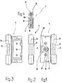
Figur 1- eine teilweise geschnittene Vorderansicht eines mit einer Höhenverstelleinrichtung versehenen Scharnierbands einer erfindungsgemäßen Scharniereinrichtung;
Figur 2- eine Seitenansicht des in
Figur 1 dargestellten Scharnierbands; Figur 3- eine Hinteransicht des in
Figur 1 dargestellten Scharnierbands; Figur 4- eine Schnittdarstellung A-A in
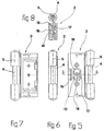
Figur 1; Figur 5- eine teilweise geschnittene Vorderansicht eines mit einer Seitenverstelleinrichtung versehenen Scharnierbands der erfindungsgemäßen Scharniereinrichtung;
Figur 6- eine Seitenansicht des in
Figur 5 dargestellten Scharnierbands; Figur 7- eine Hinteransicht des in
Figur 5 dargestellten Scharnierbands; Figur 8- eine Schnittdarstellung B-B aus
Figur 5; Figur 9- eine Draufsicht auf einen Exzenter, wie er in den
in den
Figuren 1 bis 8 dargestellten Scharnierbändern zum Einsatz kommt; und Figur 10- eine Seitenansicht des in
Figur 9 dargestellten Exzenters.
- Figure 1
- a partially sectioned front view of a hinge band provided with a height adjustment device of a hinge device according to the invention;
- Figure 2
- a side view of the hinge strap shown in Figure 1;
- Figure 3
- a rear view of the hinge strap shown in Figure 1;
- Figure 4
- a sectional view AA in Figure 1;
- Figure 5
- a partially sectioned front view of a hinge band provided with a side adjustment device of the hinge device according to the invention;
- Figure 6
- a side view of the hinge strap shown in Figure 5;
- Figure 7
- a rear view of the hinge strap shown in Figure 5;
- Figure 8
- a sectional view BB of Figure 5;
- Figure 9
- a plan view of an eccentric, as it is used in the hinge straps shown in Figures 1 to 8; and
- Figure 10
- a side view of the eccentric shown in Figure 9.
Eine erfindungsgemäße Scharniereinrichtung dient zur schwenkbaren Lagerung eines Türflügels an einem Rahmen, einer Zarge od.dgl.A hinge device according to the invention is used for pivoting Storage of a door leaf on a frame, a frame or the like.
Die anhand der Figuren 1 bis 10 dargestellte und im folgenden
näher erläuterte Ausführungsform der erfindungsgemäßen Scharniereinrichtung
besteht zumindest aus zwei Scharnierbändern
1, 2, wie sie in den Figuren 1 bis 4 bzw. 5 bis 8 in unterschiedlichen
Ansichten dargestellt sind. The illustrated with reference to Figures 1 to 10 and below
embodiment of the hinge device according to the invention explained in more detail
consists of at least two
Das Scharnierband 1 sowie das Scharnierband 2 sind mit ihrem
Schwenkbolzen 3 bzw. 4 auf derselben Schwenkachse 5 angeordnet,
so daß der in den Figuren nicht dargestellte Türflügel
um diese Schwenkachse 5 verschwenkbar am Rahmen, an der Zarge
od.dgl. gelagert ist.The
Etwaige weitere Scharnierbänder der erfindungsgemäßen Scharniereinrichtung
sind mit ihren Schwenkbolzen ebenfalls auf
dieser Schwenkachse 5 angeordnet.Any further hinge straps of the hinge device according to the invention
are also on with their pivot bolts
this
Das in den Figuren 1 bis 4 dargestellte Scharnierband 1 ist
mit einer Höhenverstelleinrichtung 6 ausgerüstet. Diese Höhenverstelleinrichtung
6 dient zur vertikalen Anpassung der
Position des Türflügels an die von ihm zu verschließende bzw.
von ihm freizugebende Öffnungsfläche des Rahmens, der Zarge
od.dgl.The
Hierzu weist die Höhenverstelleinrichtung 6 einen Exzenter 7
auf. Eine Exzenterscheibe 8 dieses Exzenters 7 ist in einer
Ausnehmung 9 eines türflügelseitigen Scharnierlappens 10 angeordnet.For this purpose, the
Die Abmessung der Ausnehmung 9 im türflügelseitigen Scharnierlappen
10 in Vertikalrichtung entspricht dem Durchmesser
der Exzenterscheibe 8 des Exzenters 7 der Höhenverstelleinrichtung.
Die Abmessung der Ausnehmung 9 im türflügelseitigen
Scharnierlappen 10 in Horizontalrichtung ist etwas größer wie
der Durchmesser der Exzenterscheibe 8 des Exzenters 7. Hierdurch
wird erreicht, daß eine etwaige Seitenverstellung des
Türflügels vorgenommen werden kann, ohne daß in irgendeiner
Weise auf die Funktion des mit der Höhenverstelleinrichtung 6
ausgerüsteten Scharnierbands 1 eingewirkt würde. The dimension of the
Eine Drehung des Exzenters 7 wird dadurch bewerkstelligt, daß
ein entsprechendes Werkzeug in einen im Exzenter 7 ausgebildeten
Sechskant 11 eingeführt und gedreht wird. Bei dieser
Drehbewegung wird der turflügelseitige Scharnierlappen 10 und
damit der Türflügel aufgrund der Exzentrizität der Exzenterscheibe
8 in bezug auf die Drehachse des Exzenters 7 je nach
Drehrichtung in aufwärtiger oder in abwärtiger Vertikalrichtung
versetzt. Hierdurch kann die Vertikalposition des Türflügels
im erforderlichen Ausmaß an die Öffnungsfläche des
Rahmens, der Zarge od.dgl. angepaßt werden.A rotation of the eccentric 7 is accomplished in that
a corresponding tool in a trained in the eccentric 7
Da auf den Exzenter 7 der Höhenverstelleinrichtung 6 ein vom
Eigengewicht des Türflügels ausgeübtes Drehmoment einwirkt,
ist bei der erfindungsgemäßen Scharniereinrichtung, wie sich
insbesondere aus Figur 9 ergibt, der Umfang der Exzenterscheibe
8 des Exzenters 7 als Aufeinanderfolge abgeflachter
Abschnitte 12 ausgebildet. Damit nun aufgrund des Eigengewichts
des Türflügels am Exzenter 7 eine Drehung erfolgt,
müßte zunächst ein Kippmoment überwunden werden. Diesbezüglich
wird der Exzenter 7 bzw. dessen Exzenterscheibe 8 mit
solchen Abmessungen versehen, daß das Eigengewicht des Türflügels
zur Überwindung dieses Kippmoments nicht ausreichend
ist.Since on the
Selbstverständlich ist es auch im Falle des vorstehend geschilderten
Scharnierbands 1 mit der den Exzenter 7 aufweisenden
Höhenverstelleinrichtung 6 möglich, das Scharnierband
1 in der korrekten Positionierung zu verklemmen, um so auch
eine ausreichende Fixierung gegen stoßartige Belastungen sicher
zu gewährleisten. In jedem Fall kann aufgrund der vorstehend
geschilderten Ausgestaltung des Scharnierbands 1 eine
Seitenverstellung der Scharniereinrichtung am im folgenden zu
beschreibenden Scharnierband 2 vorgenommen werden, ohne daß
die einmal eingestellte vertikale Position des Türflügels
durch irgendwelche Maßnahmen am Scharnierband 1 fixiert werden
müßte. Während derartiger Montagearbeiten reicht die Exzentrizität
der Exzenterscheibe 8 des Exzenters 7 der Höhenverstelleinrichtung
6 ohne weiteres aus, um den Türflügel in
der eingestellten Vertikalposition zu halten.Of course, it is also in the case of the
Bei der anhand der Figuren 1 bis 10 dargestellten erfindungsgemäßen
Scharniereinrichtung ist auch eine im in den Figuren
5 bis 8 dargestellten Scharnierband 2 realisierte Seitenverstelleinrichtung
13 mit einem Exzenter 14 versehen, welcher
dem vorstehend geschilderten Exzenter 7 der Höhenverstelleinrichtung
6 entspricht. Wie sich aus den Figuren 9 und 10 ergibt,
hat der Exzenter 14 der Seitenverstelleinrichtung 13
eine Exzenterscheibe 15, welche ebenfalls die Aufeinanderfolge
abgeflachter Abschnitte 12 aufweist.In the case of the invention shown in FIGS. 1 to 10
Hinge device is also one in the figures
5 to 8 shown
Diese Exzenterscheibe 15 des Exzenters 14 der Seitenverstelleinrichtung
ist in einer Ausnehmung 16 eines im Scharnierband
2 aufgenommenen türflügelseitigen Scharnierlappens 17
aufgenommen. Die Ausnehmung 16 dieses türflügelseitigen
Scharnierlappens 17 hat in Seitenrichtung eine Abmessung,
welche dem Durchmesser der Exzenterscheibe 15 des Exzenters
14 der Seitenverstelleinrichtung 13 entspricht. Eine Drehung
des Exzenters 14 hat aufgrund der Exzentrizität der Exzenterscheibe
15 somit zur Folge, daß der Scharnierlappen 17 und
damit der Türflügel in seitlicher Richtung auf die Schwenkachse
5 des Türflügels zu oder von dieser weg bewegt wird.
Diese Bewegung des Türflügels ist möglich, da im anhand der
Figuren 1 bis 4 geschilderten Scharnierband 1 die seitliche
Erstreckung der Ausnehmung 9 des türflügelseitigen Scharnierlappens
10 größer ist als der Durchmesser der Exzenterscheibe
8 des Exzenters 7 der Höhenverstelleinrichtung 6.This
Entsprechend ist im Falle der Ausnehmung 16 des türflügelseitigen
Scharnierlappens 17 des mit der Seitenverstelleinrichtung
13 versehenen Scharnierbands 2 die Vertikalabmessung
größer gewählt als der Durchmesser der Exzenterscheibe 15 des
Exzenters 14. Hierdurch kann eine Höhenverstellung des Türflügels
vorgenommen werden, ohne daß irgendwelche Funktionen
des Scharnierbands 2 bzw. der Seitenverstelleinrichtung 13
beeinträchtigt würden.The corresponding is in the case of the
Die abgeflachten Abschnitte 12 der Exzenterscheibe 15 des Exzenters
14 der Seitenverstelleinrichtung verhindern unerwünschte
seitliche Verstellungen des Türflügels in bezug auf
die Zarge, den Rahmen od.dgl. bei der Montage der Tür, da das
für eine seitliche Bewegung des Türflügels erforderliche
Drehmoment nicht ausreicht, um das aufgrund der abgeflachten
Abschnitte 12 zu überwindende Kippmoment zu erreichen.The flattened
Mit der vorstehend geschilderten Scharniereinrichtung kann somit von einer Person sukzessive die Position des Türflügels an die Position der Öffnungsebene des Rahmens, der Zarge od.dgl. angepaßt werden, wobei die Anpassung sowohl in Vertikal- als auch in Horizontalrichtung in einer Vielzahl kleiner Schritte erfolgen kann, ohne daß zwischenzeitlich, d.h. vor der endgültigen und korrekten Positionierung des Türflügels, irgendwelche Klemmungen oder Fixierungen vorgenommen werden müßten.With the hinge device described above thus the position of the door leaf successively from one person to the position of the opening plane of the frame, the frame or the like. be adjusted, with the adjustment being smaller in both the vertical and horizontal directions Steps can be taken without intermittent, i.e. in front the final and correct positioning of the door leaf, any clamps or fixations are made ought to.
Claims (9)
Applications Claiming Priority (2)
| Application Number | Priority Date | Filing Date | Title |
|---|---|---|---|
| DE1999151155 DE19951155C2 (en) | 1999-10-23 | 1999-10-23 | hinge device |
| DE19951155 | 1999-10-23 |
Publications (3)
| Publication Number | Publication Date |
|---|---|
| EP1094183A2 true EP1094183A2 (en) | 2001-04-25 |
| EP1094183A3 EP1094183A3 (en) | 2002-10-30 |
| EP1094183B1 EP1094183B1 (en) | 2015-10-28 |
Family
ID=7926678
Family Applications (1)
| Application Number | Title | Priority Date | Filing Date |
|---|---|---|---|
| EP00119543.7A Expired - Lifetime EP1094183B1 (en) | 1999-10-23 | 2000-09-07 | Hinge device |
Country Status (3)
| Country | Link |
|---|---|
| EP (1) | EP1094183B1 (en) |
| DE (1) | DE19951155C2 (en) |
| PL (1) | PL204761B1 (en) |
Cited By (6)
| Publication number | Priority date | Publication date | Assignee | Title |
|---|---|---|---|---|
| WO2003029589A1 (en) * | 2001-08-29 | 2003-04-10 | Frip Ab | Hinge device |
| GB2383081A (en) * | 2001-12-13 | 2003-06-18 | J K Furnex Ltd | Hinge providing height, lateral and compression adjustment |
| US6757939B2 (en) * | 2000-11-02 | 2004-07-06 | Grass Gmbh | Cabinet hinge |
| US7552511B2 (en) | 2006-07-28 | 2009-06-30 | Creative Research & Development, Inc. | Adjustable hinge |
| US7694388B2 (en) | 2006-08-30 | 2010-04-13 | Creative Research & Development, Inc. | Adjustable hinge |
| DE102012011048A1 (en) | 2012-06-02 | 2013-12-05 | Diehl Comfort Modules GmbH | Alignable hinge device for use as e.g. floating bearing, for door installation, has eccentric cam cases arranged in bearing device, so that bearing device is displaceable relative to pivotable insert in X-Y plane by eccentric cam |
Families Citing this family (7)
| Publication number | Priority date | Publication date | Assignee | Title |
|---|---|---|---|---|
| DE102006060463B3 (en) * | 2006-12-19 | 2008-04-03 | Bartels Systembeschläge GmbH | Strip holder for inserting into door casements comprises an adjusting unit with an adjusting plate penetrated by an adjusting spindle |
| DE102008036151A1 (en) | 2008-08-01 | 2010-02-04 | Glutz Deutschland Gmbh | Hinge strap with a substructure for attachment to a door leaf |
| DE102010030814A1 (en) * | 2010-07-01 | 2012-01-05 | Bayerische Motoren Werke Aktiengesellschaft | Device for fastening mounting member to single or multilayer wall region of back door of motor car, has holder held in proximity to mounting position such that holder enables non- or small rotational motion opposite to axis of screw |
| DE102011080470A1 (en) | 2011-08-05 | 2013-02-07 | Robert Bosch Gmbh | Rotational torque transmission device e.g. pulley mounted in alternator for motor car, has side portion that is provided with projection portion, on which internal thread is formed |
| DE102011080475A1 (en) | 2011-08-05 | 2013-02-07 | Robert Bosch Gmbh | Device for fixing magnets |
| DE102011085118A1 (en) | 2011-10-24 | 2013-04-25 | Robert Bosch Gmbh | Holder for electrical machines |
| DE102016003040A1 (en) * | 2016-03-14 | 2017-09-14 | Gustav Kauls Gmbh & Co. Kg | Three-dimensionally adjustable belt system |
Citations (3)
| Publication number | Priority date | Publication date | Assignee | Title |
|---|---|---|---|---|
| EP0497107A1 (en) * | 1991-01-26 | 1992-08-05 | AUGUST BILSTEIN GMBH & CO. KG | Corner support unit for wingside |
| FR2710942A1 (en) * | 1993-10-06 | 1995-04-14 | Tordo Belgrano Sa | Device for adjusting the position between an opening frame or leaf and a fixed frame |
| DE19732702A1 (en) * | 1997-07-30 | 1999-02-04 | Haps & Sohn Gmbh & Co Kg | Hinge lug for door or window |
Family Cites Families (2)
| Publication number | Priority date | Publication date | Assignee | Title |
|---|---|---|---|---|
| DE2041138C3 (en) * | 1970-08-19 | 1980-04-24 | Daimler-Benz Ag, 7000 Stuttgart | Working method for adding and setting up a door |
| ES281991Y (en) * | 1982-06-28 | 1986-07-16 | Ets. H. Gerard Et Didier | HARDWARE FORMING HINGE FOR DOOR SWING OR ROOM SHUTTER |
-
1999
- 1999-10-23 DE DE1999151155 patent/DE19951155C2/en not_active Expired - Lifetime
-
2000
- 2000-09-07 EP EP00119543.7A patent/EP1094183B1/en not_active Expired - Lifetime
- 2000-09-21 PL PL342682A patent/PL204761B1/en unknown
Patent Citations (3)
| Publication number | Priority date | Publication date | Assignee | Title |
|---|---|---|---|---|
| EP0497107A1 (en) * | 1991-01-26 | 1992-08-05 | AUGUST BILSTEIN GMBH & CO. KG | Corner support unit for wingside |
| FR2710942A1 (en) * | 1993-10-06 | 1995-04-14 | Tordo Belgrano Sa | Device for adjusting the position between an opening frame or leaf and a fixed frame |
| DE19732702A1 (en) * | 1997-07-30 | 1999-02-04 | Haps & Sohn Gmbh & Co Kg | Hinge lug for door or window |
Cited By (10)
| Publication number | Priority date | Publication date | Assignee | Title |
|---|---|---|---|---|
| US6757939B2 (en) * | 2000-11-02 | 2004-07-06 | Grass Gmbh | Cabinet hinge |
| WO2003029589A1 (en) * | 2001-08-29 | 2003-04-10 | Frip Ab | Hinge device |
| US7350272B2 (en) | 2001-08-29 | 2008-04-01 | Frip Ab | Hinge device |
| US7516517B2 (en) | 2001-08-29 | 2009-04-14 | Frip Ab | Hinge device |
| GB2383081A (en) * | 2001-12-13 | 2003-06-18 | J K Furnex Ltd | Hinge providing height, lateral and compression adjustment |
| GB2383081B (en) * | 2001-12-13 | 2005-06-01 | J K Furnex Ltd | Hinges |
| US7552511B2 (en) | 2006-07-28 | 2009-06-30 | Creative Research & Development, Inc. | Adjustable hinge |
| US7694388B2 (en) | 2006-08-30 | 2010-04-13 | Creative Research & Development, Inc. | Adjustable hinge |
| DE102012011048A1 (en) | 2012-06-02 | 2013-12-05 | Diehl Comfort Modules GmbH | Alignable hinge device for use as e.g. floating bearing, for door installation, has eccentric cam cases arranged in bearing device, so that bearing device is displaceable relative to pivotable insert in X-Y plane by eccentric cam |
| DE102012011048B4 (en) * | 2012-06-02 | 2014-01-02 | Diehl Comfort Modules GmbH | Hinge device and a door system with the hinge device |
Also Published As
| Publication number | Publication date |
|---|---|
| EP1094183B1 (en) | 2015-10-28 |
| PL204761B1 (en) | 2010-02-26 |
| DE19951155A1 (en) | 2001-05-10 |
| PL342682A1 (en) | 2001-05-07 |
| DE19951155C2 (en) | 2003-02-06 |
| EP1094183A3 (en) | 2002-10-30 |
Similar Documents
| Publication | Publication Date | Title |
|---|---|---|
| DE102007017916B3 (en) | Door hinge arrangement for closing e.g. housing opening, has bolts pointing in direction of housing, and unlockable spring prestressed locking device effective at bolts and retaining bolts in withdrawn position | |
| EP1094183A2 (en) | Hinge device | |
| DE3010703A1 (en) | DOOR CLOSER ARRANGEMENT | |
| DE2430443A1 (en) | HINGE ASSEMBLY | |
| DE102005033098B4 (en) | Tailgate for a motor vehicle | |
| WO2008061611A1 (en) | Door hinge, in particular edge hinge | |
| WO2008003106A1 (en) | Furniture hinge | |
| DE102009004210B3 (en) | A door hinge arrangement | |
| DE1653994B2 (en) | Motor vehicle door lock | |
| EP0837206B1 (en) | Door hinge for swingingly supporting a door leaf from a door frame | |
| EP0562444B1 (en) | Hinge fitting with multiple articulation for vehicle door or tailboard | |
| DE4308956C2 (en) | Frame for the adjustable mounting of an insect screen | |
| WO2007137644A1 (en) | Hinge featuring improved fixture of the hinge pin | |
| DE1225988B (en) | Opening device for tilt and turn windows, doors or the like. | |
| DE2443036C3 (en) | Opening device | |
| DE3001070A1 (en) | CORNER JOINT FOR TURN-TIP WINDOWS, DOORS OR THE LIKE | |
| DE3044674A1 (en) | Adjustable door hinge strip bearing socket - has disc lugs engaging surrounding hole grooves and depressions in it | |
| EP0874123B1 (en) | Fitting for supporting a window or door swinging wing | |
| DE19829503B4 (en) | Articulated wheel, in particular for glass pendulum doors | |
| EP1400648A2 (en) | System for opening and closing of lids, especially of tailgates of motor vehicles | |
| CH622578A5 (en) | Fitting for the opening and simultaneous lifting of doors or gates | |
| EP0340455B1 (en) | Pivot bearing for the connection of two wings of a window, door or the like | |
| WO1994000661A1 (en) | Revolving door | |
| EP0976594A1 (en) | Cargo door | |
| DE3822000C2 (en) |
Legal Events
| Date | Code | Title | Description |
|---|---|---|---|
| PUAI | Public reference made under article 153(3) epc to a published international application that has entered the european phase |
Free format text: ORIGINAL CODE: 0009012 |
|
| AK | Designated contracting states |
Kind code of ref document: A2 Designated state(s): AT BE CH CY DE DK ES FI FR GB GR IE IT LI LU MC NL PT SE |
|
| AX | Request for extension of the european patent |
Free format text: AL;LT;LV;MK;RO;SI |
|
| PUAL | Search report despatched |
Free format text: ORIGINAL CODE: 0009013 |
|
| AK | Designated contracting states |
Kind code of ref document: A3 Designated state(s): AT BE CH CY DE DK ES FI FR GB GR IE IT LI LU MC NL PT SE |
|
| AX | Request for extension of the european patent |
Free format text: AL;LT;LV;MK;RO;SI |
|
| 17P | Request for examination filed |
Effective date: 20030402 |
|
| AKX | Designation fees paid |
Designated state(s): AT BE CH CY DE DK ES FI FR GB GR IE IT LI LU MC NL PT SE |
|
| 17Q | First examination report despatched |
Effective date: 20030717 |
|
| RIN1 | Information on inventor provided before grant (corrected) |
Inventor name: JAHNKE, WOLFANG Inventor name: NEUKOETTER, HUBERT |
|
| 17Q | First examination report despatched |
Effective date: 20030717 |
|
| GRAJ | Information related to disapproval of communication of intention to grant by the applicant or resumption of examination proceedings by the epo deleted |
Free format text: ORIGINAL CODE: EPIDOSDIGR1 |
|
| GRAP | Despatch of communication of intention to grant a patent |
Free format text: ORIGINAL CODE: EPIDOSNIGR1 |
|
| GRAP | Despatch of communication of intention to grant a patent |
Free format text: ORIGINAL CODE: EPIDOSNIGR1 |
|
| INTG | Intention to grant announced |
Effective date: 20150511 |
|
| GRAS | Grant fee paid |
Free format text: ORIGINAL CODE: EPIDOSNIGR3 |
|
| GRAA | (expected) grant |
Free format text: ORIGINAL CODE: 0009210 |
|
| AK | Designated contracting states |
Kind code of ref document: B1 Designated state(s): AT BE CH CY DE DK ES FI FR GB GR IE IT LI LU MC NL PT SE |
|
| REG | Reference to a national code |
Ref country code: GB Ref legal event code: FG4D Free format text: NOT ENGLISH |
|
| REG | Reference to a national code |
Ref country code: CH Ref legal event code: EP |
|
| REG | Reference to a national code |
Ref country code: AT Ref legal event code: REF Ref document number: 758043 Country of ref document: AT Kind code of ref document: T Effective date: 20151115 |
|
| REG | Reference to a national code |
Ref country code: IE Ref legal event code: FG4D Free format text: LANGUAGE OF EP DOCUMENT: GERMAN |
|
| REG | Reference to a national code |
Ref country code: DE Ref legal event code: R096 Ref document number: 50016427 Country of ref document: DE |
|
| REG | Reference to a national code |
Ref country code: NL Ref legal event code: MP Effective date: 20151028 |
|
| PG25 | Lapsed in a contracting state [announced via postgrant information from national office to epo] |
Ref country code: IT Free format text: LAPSE BECAUSE OF FAILURE TO SUBMIT A TRANSLATION OF THE DESCRIPTION OR TO PAY THE FEE WITHIN THE PRESCRIBED TIME-LIMIT Effective date: 20151028 Ref country code: NL Free format text: LAPSE BECAUSE OF FAILURE TO SUBMIT A TRANSLATION OF THE DESCRIPTION OR TO PAY THE FEE WITHIN THE PRESCRIBED TIME-LIMIT Effective date: 20151028 Ref country code: ES Free format text: LAPSE BECAUSE OF FAILURE TO SUBMIT A TRANSLATION OF THE DESCRIPTION OR TO PAY THE FEE WITHIN THE PRESCRIBED TIME-LIMIT Effective date: 20151028 |
|
| PG25 | Lapsed in a contracting state [announced via postgrant information from national office to epo] |
Ref country code: SE Free format text: LAPSE BECAUSE OF FAILURE TO SUBMIT A TRANSLATION OF THE DESCRIPTION OR TO PAY THE FEE WITHIN THE PRESCRIBED TIME-LIMIT Effective date: 20151028 Ref country code: PT Free format text: LAPSE BECAUSE OF FAILURE TO SUBMIT A TRANSLATION OF THE DESCRIPTION OR TO PAY THE FEE WITHIN THE PRESCRIBED TIME-LIMIT Effective date: 20160229 Ref country code: FI Free format text: LAPSE BECAUSE OF FAILURE TO SUBMIT A TRANSLATION OF THE DESCRIPTION OR TO PAY THE FEE WITHIN THE PRESCRIBED TIME-LIMIT Effective date: 20151028 Ref country code: GR Free format text: LAPSE BECAUSE OF FAILURE TO SUBMIT A TRANSLATION OF THE DESCRIPTION OR TO PAY THE FEE WITHIN THE PRESCRIBED TIME-LIMIT Effective date: 20160129 |
|
| REG | Reference to a national code |
Ref country code: DE Ref legal event code: R097 Ref document number: 50016427 Country of ref document: DE |
|
| PG25 | Lapsed in a contracting state [announced via postgrant information from national office to epo] |
Ref country code: DK Free format text: LAPSE BECAUSE OF FAILURE TO SUBMIT A TRANSLATION OF THE DESCRIPTION OR TO PAY THE FEE WITHIN THE PRESCRIBED TIME-LIMIT Effective date: 20151028 |
|
| PLBE | No opposition filed within time limit |
Free format text: ORIGINAL CODE: 0009261 |
|
| STAA | Information on the status of an ep patent application or granted ep patent |
Free format text: STATUS: NO OPPOSITION FILED WITHIN TIME LIMIT |
|
| 26N | No opposition filed |
Effective date: 20160729 |
|
| PG25 | Lapsed in a contracting state [announced via postgrant information from national office to epo] |
Ref country code: BE Free format text: LAPSE BECAUSE OF NON-PAYMENT OF DUE FEES Effective date: 20160930 |
|
| REG | Reference to a national code |
Ref country code: DE Ref legal event code: R119 Ref document number: 50016427 Country of ref document: DE |
|
| PG25 | Lapsed in a contracting state [announced via postgrant information from national office to epo] |
Ref country code: MC Free format text: LAPSE BECAUSE OF FAILURE TO SUBMIT A TRANSLATION OF THE DESCRIPTION OR TO PAY THE FEE WITHIN THE PRESCRIBED TIME-LIMIT Effective date: 20151028 |
|
| REG | Reference to a national code |
Ref country code: CH Ref legal event code: PL |
|
| GBPC | Gb: european patent ceased through non-payment of renewal fee |
Effective date: 20160907 |
|
| REG | Reference to a national code |
Ref country code: IE Ref legal event code: MM4A |
|
| REG | Reference to a national code |
Ref country code: FR Ref legal event code: ST Effective date: 20170531 |
|
| PG25 | Lapsed in a contracting state [announced via postgrant information from national office to epo] |
Ref country code: GB Free format text: LAPSE BECAUSE OF NON-PAYMENT OF DUE FEES Effective date: 20160907 Ref country code: DE Free format text: LAPSE BECAUSE OF NON-PAYMENT OF DUE FEES Effective date: 20170401 Ref country code: CH Free format text: LAPSE BECAUSE OF NON-PAYMENT OF DUE FEES Effective date: 20160930 Ref country code: FR Free format text: LAPSE BECAUSE OF NON-PAYMENT OF DUE FEES Effective date: 20160930 Ref country code: LI Free format text: LAPSE BECAUSE OF NON-PAYMENT OF DUE FEES Effective date: 20160930 Ref country code: IE Free format text: LAPSE BECAUSE OF NON-PAYMENT OF DUE FEES Effective date: 20160907 |
|
| PG25 | Lapsed in a contracting state [announced via postgrant information from national office to epo] |
Ref country code: LU Free format text: LAPSE BECAUSE OF NON-PAYMENT OF DUE FEES Effective date: 20160907 |
|
| REG | Reference to a national code |
Ref country code: AT Ref legal event code: MM01 Ref document number: 758043 Country of ref document: AT Kind code of ref document: T Effective date: 20160907 |
|
| REG | Reference to a national code |
Ref country code: BE Ref legal event code: MM Effective date: 20160930 |
|
| PG25 | Lapsed in a contracting state [announced via postgrant information from national office to epo] |
Ref country code: AT Free format text: LAPSE BECAUSE OF NON-PAYMENT OF DUE FEES Effective date: 20160907 |
|
| PG25 | Lapsed in a contracting state [announced via postgrant information from national office to epo] |
Ref country code: CY Free format text: LAPSE BECAUSE OF FAILURE TO SUBMIT A TRANSLATION OF THE DESCRIPTION OR TO PAY THE FEE WITHIN THE PRESCRIBED TIME-LIMIT Effective date: 20151028 |